1
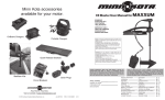
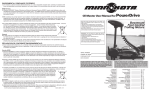
Master User Manual for FORTREX BOWMOUNT BOWGUARD 360°® FOOT CONTROL LIFT ASSIST TROLLING MOTOR MOTEUR DE P CHE BOWGUARD 360°® À LEVAGE ASSISTÉ, PÉDALE DE COMMANDE ET MONTAGE SUR PROUE NOTE: Do not return your Minn Kota motor to your retailer. Your retailer is not authorized to repair or replace this unit. You may obtain service by: • calling Minn Kota at 1-800-227-6433 or 1-507-345-4623; • returning your motor to the Minn Kota Factory Service Center; • sending or taking your motor‑‑‑ to any Minn Kota authorized service center on enclosed list. Please include proof of purchase, serial number and purchase date for warranty service with any of the above options. REMARQUE: Ne pas retourner le moteur Minn Kota au concessionnaire. Ce dernier n’est pas autorisé à le réparer ou à le remplacer. En cas de panne: • Contacter Minn Kota au 1-800-227-6433 ou au 1-507-345-4623; • Retourner le moteur à l’usine Minn Kota; • Ou à un centre de Minn Kota agréé de la liste suivante. Quelle que soit l’option, joindre la facture, mentionner le n° de série et la date d’achat pour bénéficier de la garantie. serial number numéro de série purchase date date d’achat PLEASE THOROUGHLY READ THIS USER MANUAL. FOLLOW ALL INSTRUCTIONS AND HEED ALL SAFETY & CAUTIONARY NOTICES BELOW. USE OF THIS MOTOR IS ONLY PERMITTED FOR PERSONS THAT HAVE READ AND UNDERSTOOD THESE USER INSTRUCTIONS. MINORS MAY USE THIS MOTOR ONLY UNDER ADULT SUPERVISION. LISEZ S’IL VOUS PLAÎT TOUT À FAIT CE MANUEL D’UTILISATEUR. SUIVEZ TOUTES LES INSTRUCTIONS ET FAITES ATTENTION À TOUTE LA SÉCURITÉ ET AUX PRÉAVIS D’AVERTISSEMENT CI-DESSOUS. L’UTILISATION DE CE MOTEUR EST SEULEMENT PERMISE POUR LES PERSONNES QUI ONT LU ET ONT COMPRIS CES INSTRUCTIONS D’UTILISATEUR. LES MINEURS PEUVENT UTILISER CE MOTEUR SEULEMENT DANS LA SUPERVISION ADULTE. Feature Information........................... Assembly.......................................... Installation......................................... Gas Assist Lift Mechanism................ Operation.......................................... Adjustments........................................ Cautions.............................................. Battery Information.............................. Battery Connection........................... Wiring Diagram................................. Circuit Breaker.................................... Propeller........................................... Maximizer™...................................... Maintenance..................................... Trouble Shooting............................... Limited Warranty............................... Description.............................................. Assemblage............................................. Pose........................................................ Mécanisme de levage assisté............... Fonctionnement....................................... Reglages................................................. Prudences............................................... Informations de batterie........................... Branchement de la batterie..................... Schéma de câblage................................ Disjoncteur.............................................. Hélice...................................................... Maximizer™............................................ Entretien.................................................. Dépannage.............................................. Garantie limitée....................................... pg. 2 pg. 3 pg. 4-5 pg. 6-7 pg. 8-9 pg. 10-11 pg. 12 pg. 13 pg. 14 pg. 15 pg. 16-17 pg. 18 pg. 19 pg. 19 pg. 20-21 pg. 22 FEATURE INFORMATION Lighted Direction Indicator Indicateur de direction éclairé Rugged Aluminum Extrusion Extrusion En aluminium Robuste Depth Collar Knob Bouton du collier de profondeur DESCRIPTION BowGuard 360°® Breakaway Protection Protection BowGuard 360°® Gas Assist Lift Mechanism Mécanisme de levage assisté Lifetime Warranty Flexible Composite Shaft Arbre composite flexible à garantie à vie Momentary Switch Commande momentanée Mom/Off/Con Switch Commande Mom./Arrêt/Continu Heel Block Butée du talon Permanent Magnet Motor Moteur à aimant permanent Rotary Speed Control Molette de réglage de la vitesse Weedless Wedge Propeller Hélice à bord anti-herbe Specifications subject to change without notice. Ces caractéristiques peuvent faire l’objet de modifications sans préavis. 2 2 • Align the end of the gas spring with the holes in the outer arm • Install pin, spacers and Phillips flat head screws • Tighten screws until the heads are flush with the outer arm 1. Place the mount on an elevated surface such as a workbench or tailgate of pickup. 2. Remove the 5/16” Allen screw and lock washer from the mount using an Allen wrench. (See picture) 3. Align the key ways on the inside of the bowguard with NOTE: Screws have a pre-applied thread locker, DO the ends links on the mount. Lower the motor assembly NOT apply additional thread locker to screws as that straight down until seated. may prevent future removal. 4. Install the 5/16” Allen screw / lock washer and tighten to 10-12 ft/lbs. 7. Motor / mount can now be installed onto the boat. 5. Stow the motor into the flat position by pulling the rope/ Proceed to next page for mounting instructions. handle to disengage the latch bar, allowing the motor to fold into the flat position. ATTENTION: The 5/16” Allen screw must be tight 6. Once in the stowed or flat position, the gas spring pin when installed and periodically tightened to 10-12 ft/lbs can be installed. Follow the steps below to install the (Step 4), which will allow the motor to be stowed propgas spring pin and spacers: erly. Tighten the Allen screw when the mount is in the • Locate the upper gas spring pin and spacers in bag deployed position. assembly Allen Screw Vis Allen ASSEMBLY ASSEMBLY OF MOTOR TO MOUNT: keys Clavettes Safety Latch Levier De Sécurité 1. Placez le montant sur une surface élevée, un banc de travail ou le hayon d’une camionnette par exemple. 2. Enlevez la vis Allen de 7,93 mm (5/16 po) et la rondelle de sûreté du montant au moyen d’une clé Allen de 6,35 mm (⁄ po). (Voyez la photo.) 3. Alignez la rainure à l’intérieur du protège proue par rapport aux maillons en bout du montant. Abaissez l’assemblage du moteur tout droit pour l’asseoir. 4. Installez le 5/16” la vis d’Allen / la machine à laver de serrure et serrez-vous à 10-12 ft/lbs. 5. Rangez le moteur à plat en tirant la poignée/corde pour débrayer la barre de blocage, permettant ainsi de plier le moteur. 6. Une fois le moteur à plat, la goupille du vérin pneumatique peut être remontée. Suivez les étapes ci-dessous pour installer cette goupille. • Trouvez l’épingle printanière supérieure du gaz dans l’assemblage de sac. • Alignez l’extrémité du vérin pneumatique par rapport aux trous du bras externe. • Remettez la goupille et la vis cruciforme à tête plate. • Serrez la vis jusqu’à ce que sa tête soit au ras du bras externe. ASSEMBLAGE ASSEMBLAGE DU MOTEUR AU MONTANT : REMARQUE: Les vis ont été enduites de colle pour filetage, N’APPLIQUEZ PAS plus de colle pour filetage sur les vis car cela pourrait empêcher de les enlever à l’avenir. 7. L’assemblage de moteur/montant peut maintenant être installé sur le bateau. Continuez à la page suivante pour les instructions de montage. ATTENTION: le 5/16” la vis d’Allen doit être serré quand installé et périodiquement serré à 10-12 ft/lbs (le Pas 4), qui permettra au moteur d’être rangé correctement. Serrez la vis d’Allen quand le mont est dans la position déployée. 3 INSTALLATION INSTALLATION OF THE BOWMOUNT: We recommend that you have another person help with this procedure. 1. For installation, do not remove the shaft/motor from the Bowguard. The Bowguard spring is under tension and must always remain secured. 2. Place the mount, with the motor in the fully retracted (flat) position, on the deck of the boat: • The motor should be mounted as close to the centerline of the boat as possible. • Make sure bow area under the chosen location is clear and unobstructed for drilling. • Make sure the motor rest is positioned far enough beyond the edge of the boat. The motor, as it is lowered into the water or raised into the boat, must not encounter any obstructions. 3. Once in position, determine which bolt pattern is to be used (see below), mark at-least 4 of the holes in the bow plate and drill through with a 9/32” drill bit. Either pattern may be used when installing the motor. Pattern 1. Minnkota 3” bolt pattern standard motors. Pattern 2. Alternate 4” bolt pattern commonly used. NOTE: If pattern 2 is to be used, the right side plate must be removed to access the mounting holes in the bow plate. 4. Install Velcro strap between the motor and deck of boat between second and third set of mounting holes. 5. Mount the plate to the bow through the drilled holes using the provided (1/4-20 x 3-1/2”) bolts, nuts and washers. NOTE: If possible, secure all sets of mounting bolts, nuts and washers. 6. Install the bow mount stabilizer (if included). See page 5 for installation instructions. CAUTION: MAKE SURE YOUR MOTOR IS MOUNTED ON A LEVEL SURFACE PRÉCAUTION : ASSUREZ-VOUS QUE LE MOTEUR EST MONTÉ SUR UNE SURFACE DE NIVEAU. Velcro Strap la bande Velcro POSE 4 MONTAGE SUR LA PROUE : Il est recommandé de se faire assister pour cette procédure. 1. Pour la pose, ne séparez pas l’arbre/moteur du gardeproue Bowguard. Le ressort du garde-proue est sous tension et doit toujours rester assuré. 2. 2. Posez le support, le moteur ramené à fond (à plat), sur le pont du bateau : • Montez le moteur le plus près possible de l’axe du bateau. • Assurez-vous qu’il n’y a pas d’obstacle au perçage dans la zone de la proue située sous l’emplacement choisi. • Assurez-vous que le support du moteur est assez loin du bord du bateau. Le moteur ne doit rencontrer aucun obstacle lorsqu’il est abaissé ou remonté. 3. 5. Montez la plaque sur la proue avec les boulons (1/4-20 x 8,89 cm (3-1/2 po)), rondelles et écrous fournis. Position the Bowmount close to the centerline of the boat and in an area free of obstructions. Positionnez le support de proue le plus près possible de l’axe du bateau et dans une zone sans obstacles. REMARQUE : Si possible, serrez tout les jeux de boulons de montage, écrous et rondelles. 4. Installez la bande Velcro entre le moteur et le pont du bateau, entre les deuxième et troisième jeux de trous de montage. 5. Montez la plaque sur la proue par les trous percés au moyen des boulons de 1/4-20 x 8,89 cm (3-1/2 po), écrous et rondelles fournis. REMARQUE: Si possible, fixez tous les jeux de boulons, écrous et rondelles de montage. 6. Installez le stabilisateur de montant de proue (si compris). Voyez la page 5 pour ses instructions d’installation. 1. Place motor in the stowed position 2. Unthread the composite rod from the bracket and attach bracket to the bottom of the bowguard using the 5/16” cap screws and nuts. The nuts fit into pocket on the inside of the bowguard behind the spring. NOTE: The bracket can be installed on the left or right side of the bowguard. 3. Pull the bumper off the stabilizer rod and place the rod next to the bracket as shown in photo. 4. Place the threaded end down onto the deck surface and mark the rod 3/4” above the top of the bracket (see photo) 5. Cut the rod to the mark and round the cut edge with a file or sandpaper. 6. Install the bottom bumper to the stabilizer rod and thread the rod into the bracket. 7.Adjust the stabilizer rod up or down to so that the tip just touches the support surface. See photo below. WARNING: Adjusting the rod too tightly removes the end play needed for proper pin engagement and doing so could prevent the mount from fully latching in the stowed position. If installed correctly, the rod tip should lift off the deck about 1/4” without the mount unlatching. 8. Once adjusted, tighten the jam nut against the bracket, which will prevent the rod from turning. 9. Install top cap if threads are exposed. INSTALLATION INSTALLING THE BOWMOUNT STABILIZER: (if Included) 3/4” 19.1mm Optional mounting holes Trous de montage optionnels 1. Placez le moteur en position rangée. 2. Dévissez la tige de composite du support et fixez le support au bas du protège proue à l’aide des vis Allen de 7,93 mm (5/16 po) et écrous. Les écrous entrent dans des cavités du protège proue derrière le ressort. POSE INSTALLER LE STABILISATEUR DU MONTANT DE PROUE (si compris) : REMARQUE: Le support peut être installé sur la droite ou la gauche du protège proue. 3. Tirez le butoir pour l’enlever de la tige du stabilisateur et placez la tige près du support comme montré dans la photo. 4. Placez l’extrémité filetée vers le bas sur la surface du pont et marquez la tige à 19,1 mm (fl po) au-dessus du haut du support (voyez la photo). 5. Coupez la tige au point marqué et arrondissez le bord coupé avec une lime ou de la toile émeri. 6. Installez le butoir inférieur sur la tige du stabilisateur et vissez la tige dans le support. 7. Réglez la tige de stabilisation de façon à ce que sa pointe touche à peine la surface de support. Voyez la photo cidessus. AVERTISSEMENT : Appuyer la tige fermement contre la surface de support pourrait éliminer le jeu en bout nécessaire pour bien emboîter la goupille, ce qui pourrait empêcher le montant de s’emboîter complètement en position de rangement. Quand elle est bien installée, la pointe de la tige devrait se lever de 6,35 à 12,7 mm (⁄ à fi po) du pont sans décrocher le montant. 8. Une fois réglé, serrez l’écrou de blocage contre le support, ce qui empêchera la tige de tourner. 9. Installez le capuchon supérieur si les filets apparaissent. 5 GAS ASSIST LIFT MECHANISM: GAS ASSIST LIFT MECHANISM WARNING: The gas assist lift mechanism in this unit is under HIGH SPRING PRESSURE when the motor is in the deployed position. DO NOT remove the BowGuard assembly from the mount without disconnecting one end of the gas spring. Failure to do this can create a condition where accidental pulling of the rope may cause the mount to spring open rapidly, striking anyone or anything in the direct path. To disconnect one end of the gas spring, follow the instructions below: 1. With the mount in the stowed position, locate the upper cylinder pin. 2. Using two Phillips screwdrivers, remove 1 of the Phillips flat head screws. 3. Remove pin and spacers from outer arm. 4. Now it is safe to deploy the motor and remove the motor assembly. 5. To re-connect the gas spring, see page 3, step 6. Phillips Screw Vis cruciforme Gas Spring Bracket ressort au pas du gaz MÉCANISME DE LEVAGE ASSISTÉ MÉCANISME DE LEVAGE ASSISTÉ: AVERTISSEMENT : Le mécanisme de levage assisté dans cette unité est sous HAUTE PRESSION PAR LE RESSORT quand le moteur est en position déployée. N’ENLEVEZ PAS l’assemblage de garde-proue du montant sans décrocher une extrémité du ressort au pas du gaz. Omettre de faire ceci peut créer une condition où tirer accidentellement la corde peut causer l’ouverture brusque du montant, heurtant quiconque ou quoi que se soit se trouvant dans sa course. Pour décrocher une extrémité du ressort au pas du gaz, suivez les instructions ci-dessous : 1. Le montant en position rangée, trouvez la goupille du vérin supérieur. 2. À l’aide de deux tournevis cruciformes, enlevez 1 des vis cruciformes à tête plate. 3. Enlevez la goupille du bras externe en la glissant à travers le bras. 4. Vous pouvez maintenant déployer sûrement le moteur et enlevez l’assemblage de moteur. 5. Pour raccorder le vérin pneumatique, voyez la page 3, étape 6. 6 WARNING: The gas assist lift mechanism in this unit is under HIGH SPRING PRESSURE when the motor is in the deployed position. DO NOT remove the BowGuard assembly from the mount without disconnecting one end of the gas spring. 1. Disconnect one end of the gas spring. see page 6 for instructions. 2. Place the motor in the deployed position. 3. Remove the 5/16” cap screw and lock washer located on the top of the bowguard, in front of the pull rope. 4. Lift motor/Bowguard assembly straight up until bowguard is free from mount. WARNING MOVING PARTS CAN CRUSH OR CUT NOTE: Rope and latch bar should never be pulled with the motor removed as the assembly is under HIGH PRESSURE. •GAS ASSIST LIFT MECHANISM IS UNDER PRESSURE 5. To re-assemble: Align the key ways on the inside of the bowguard with the ends links on the mount. Lower the assembly straight down until seated Re-install the 5/16” cap screw and washer and tighten. •DISCONNECT GAS SPRING BEFORE REMOVING MOTOR FROM MOUNT GAS ASSIST LIFT MECHANISM REMOVAL OF THE BOWGUARD: •DO NOT PULL ROPE UNTIL GAS SPRING IS DISCONNECTED Allen Screw Vis Allen AVERTISSEMENT AVERTISSEMENT : Le mécanisme de levage assisté dans cette unité est sous HAUTE PRESSION PAR LE RESSORT quand le moteur est en position déployée. N’ENLEVEZ PAS l’assemblage de garde-proue du montant sans décrocher une extrémité du ressort au pas du gaz. REMARQUE: La corde et la barre de blocage ne devraient jamais être tirées quand le moteur est enlevé car l’assemblage est sous GRANDE PRESSION. 5. Pour remonter : Alignez la rainure à l’intérieur du protège proue par rapport aux maillons en bout du montant. Abaissez l’assemblage du moteur tout droit pour l’asseoir. Remettez la vis Allen de 7,93 mm (5/16 po) et la rondelle, puis serrez-les. •LE MÉCANISME DE LEVAGE ASSISTÉ EST SOUS PRESSION. •DÉCROCHEZ LE RESSORT AU PAS DU GAZ AVANT D’ENLEVER LE MOTEUR DU MONTANT. •NE TIREZ PAS LA CORDE SANS TOUT D’ABORD AVOIR DÉCROCHÉ LE RESSORT AU PAS DU GAZ. 1. Décrochez un côté du vérin pneumatique. Reportez-vous à la page 6 pour les instructions. 2. Placez le moteur en position déployée. 3. Enlevez la vis Allen de 7,93 mm (5/16 po) et la rondelle de sûreté situées au haut du protège proue, devant la corde. 4. Levez l’assemblage moteur/protège proue tout droit jusqu’à ce que le protège proue soit séparé du montant. LES PIÈCES MOBILES PEUVENT ÉCRASSER OU COUPER. MÉCANISME DE LEVAGE ASSISTÉ DÉPOSE DU GARDE-PROUE : 7 OPERATION FOOT PEDAL CONTROLS: Most controls on the remote foot pedal are easy to operate by either foot or hand: • Rotary Speed Control. These motors offer infinitely variable speeds. Turn the knob clockwise to increase speed and counter-clockwise to decrease speed. • MOM / OFF / CON Switch. When depressed to CON, the “constant on” allows you to run continuously without keeping your foot on the pedal. Depress the switch MOM for momentary operation or to OFF. • Momentary Switch. With the MON / OFF / CON set to “MOM”, a toe touch on the “momentary” switch turns the motor on. Let up and the motor stops. • Right /Left. Push the toe end of the foot rest down to turn right and push the heel end of the foot rest down to turn left. Watch the lighted indicator on the motor head to check direction. • Forward/Reverse. The motor always drives forward by depressing the constant on or momentary switch. You can reverse the direction of thrust by turning the motor 180°. CAUTION: SWITCH THE MOM / OFF / CON CONTROL TO OFF WHEN NOT IN USE. IF THE MOTOR CONTROL IS LEFT ON AND THE PROPELLER ROTATION IS BLOCKED, SEVERE MOTOR DAMAGE CAN RESULT. TROLLING MOTOR WILL DEPLETE BATTERY IF SWITCH IS LEFT IN MOM (MOMENTARY) OR CON (CONTINUOUS) POSITION. FONCTIONNEMENT PÉDALE DE COMMANDE : La plupart des commandes peuvent être facilement effectuées à la main ou au pied à partir de la pédale de commande : • Molette de réglage de la vitesse. Ces moteurs permettent une gamme infinie de vitesses. Tournez la molette dans le sens horaire pour accélérer et dans le sens inverse pour ralentir. • Commande MOM/OFF/CON (momentané/arrêt/continu). Mettez la commande sur « CON » pour « Continu » pour faire tourner le moteur continuellement sans avoir à laisser le pied sur la pédale. Appuyez sur « MOM » pour un fonctionnement momentané. • Commande momentanée. La commande MON / OFF / CON sur « MOM », une simple pression sur la commande « MOM » met le moteur en marche. Il s’arrête dès que la touche est relâchée. • Droite/gauche. Appuyez sur l’avant de la pédale pour tourner à droite et sur le talon pour tourner à gauche. Voyez l’indicateur lumineux sur le boîtier de commande pour vérifier la direction. • Inverseur de marche. Le moteur tourne toujours dans le même sens. Pour inverser le sens de marche, pivotez le moteur de 180°. ATTENTION : METTEZ TOUJOURS LA COMMANDE MOM / OFF / CON SUR ARR T LORSQUE LE MOTEUR N’EST PAS UTILISÉ. SI LA COMMANDE DU MOTEUR EST SUR MARCHE ET L’HÉLICE EST COINCÉE, LE MOTEUR RISQUE D’ TRE ENDOMMAGÉ. TROLLING MOTEUR ÉPUISER LA BATTERIE SI L’INTERRUPTEUR EST À GAUCHE DANS MOM (MOMENTANÉE) OU CON (CONTINU) POSITION. 8 The bowmount is designed to fold back and lock the motor flat on the deck when not in use and to provide secure stowage for transport. • The pull rope releases the lock bar, which automatically engages when the unit is lowered or raised into position. The pull grip and rope should be used to both lower and raise the unit. • The motor rest positions the lower unit as it comes in contact with the nose of the mount and guides it onto the motor rest. WARNING : WHEN RAISING OR LOWERING MOTOR, KEEP FINGERS CLEAR OF ALL HINGE AND PIVOT POINTS AND ALL MOVING PARTS. WARNING: WHEN INCLUDED WITH MOTOR, THE VELCRO STRAP AND STABILIZER MUST BE USED WHEN MOTOR IS IN THE STOWED POSITION. FAILURE TO INSTALL AND USE THESE SUPPLIED PARTS MAY RESULT IN DAMAGE TO THE MOTOR NOT COVERED BY THE PRODUCT WARRANTY. Le montage de proue est prévu pour se replier et pour verrouiller le moteur à plat sur le pont lorsqu’il n’est pas utilisé et pour le transport. • Le cordon libère la barre de verrouillage qui s’engage automatiquement lorsque le moteur est abaissé ou relevé en position. Utilisez la poignée et le cordon pour abaisser et pour relever le moteur. • Le repos du moteur positionne le moteur lorsqu’il touche le nez du support et le guide dans le repos. FONCTIONNEMENT FONCTIONNEMENT DU SUPPORT : ATTENTION : LORS DE L’ABAISSEMENT OU DU RELEVAGE DU MOTEUR, VEILLEZ À NE PAS METTRE LES DOIGTS PRÈS DES POINTS DE PINCEMENT ET DES PIÈCES MOBILES. OPERATION BOW MOUNT OPERATION: AVERTISSMENT:QUAND COMPRIS AVEC LE MOTEUR, LA BRIDE VELCRO ET LE STABILISATEUR DOIVENT ÊTRE UTILISÉS QUAND LE MOTEUR EST EN POSITION DE REMORQUAGE. NE PAS INSTALLER ET UTILISER CES PIÈCES FOURNIES PEUT ENTRAÎNER DES DÉGÂTS AU MOTEUR N’ÉTANT PAS COUVERTS PAR LA GARANTIE. 9 DEPTH ADJUSTMENT: ADJUSTMENTS • • • • • Firmly grasp the outer shaft or control head and hold it steady. Loosen the depth setting knob on the depth collar until the shaft slides freely. Raise or lower the motor to the desired depth. Turn the motor control head to the desired position. Tighten depth setting knob to secure the motor in place. NOTE: When setting the depth be sure the top of the motor is submerged at least 12” to avoid churning or agitation of surface water. The propeller must be completely submerged. Depth Setting Knob Bouton de réglage de la profondeur 12” Minimum depth Profondeur de 30 cm minimum REGLAGES RÉGLAGE DE LA PROFONDEUR : • • • • • Saisissez fermement l’arbre extérieur ou le boîtier de commande et immobilisez-le. Desserrez le collier de serrage jusqu’à ce que l’arbre coulisse librement. Remontez ou abaissez le moteur à la profondeur voulue. Tournez le boîtier de commande sur la position voulue. Serrez le collier de serrage pour fixer le moteur en place. REMARQUE : Lors du réglage de la profondeur, assurez-vous que le haut du moteur est immergé d’au moins 30 cm (12 po) pour éviter tout remous à la surface de l’eau. L’hélice doit être entièrement immergée. 10 CABLE ADJUSTMENT: The steering cable tension is pre-set at the factory but will, through normal use, need occasional adjustment. Adjust the tension by turning the Phillips screw located near the bottom of the foot pedal, just under the steering cable cover. Cable Tension Adjustment Screw Vis de réglage de la tension du câble ADJUSTMENTS Turn the screw clockwise to increase tension and counter-clockwise to decrease tension. NOTE: If the cable becomes too loose, it may disengage for either the roller drum in the control box or the pulley in the foot pedal. Stainless Steel Cable Câble d’acier inoxydable Cable Pulley Poulie de câble RÉGLAGE DU CÂBLE: Tournez la vis dans le sens horaire pour augmenter la tension et dans le sens contraire pour la diminuer. REGLAGES Le câble de direction est pré-réglé en usine mais l’usure normale doit être compensée de temps à autre. Pour régler la longueur et la tension, tournez la vis de réglage située près du bas la pédale de commande sous le couvercle du câble de commande. REMARQUE : Si le câble est trop détendu, il peut sortir du tambour dans le boîtier de commande ou de la poulie dans la pédale. 11 CAUTIONS Attention: •Avoid running your motor with the propeller out of the water. This may result in injuries from the rotating propeller. •It is recommended to set the speed selector to zero and place the motor in the deployed position prior to connecting power cables. •Always ensure that the power cables are not twisted or kinked; and that they are securely routed to avoid a safety or trip hazard. Ensure cables are unobstructed in all locations to avoid damaging the wire insulation. Damage to the insulation could result in failure or injury. •Always inspect the insulation of the power cables prior to use to ensure they are not damaged. •Disregarding these safety precautions may result in an electrical short of the battery(s) and/or motor. Always disconnect the motor from the battery(s) before cleaning or checking the propeller. •Avoid submerging the complete motor as water may enter the lower unit through control head and shaft. Water in the lower unit may cause an electrical short and damage the lower unit. This damage will not be covered by warranty. Caution! •Always operate the motor in a safe distance away from obstructions. Never approach the motor when the propeller is running. Contact with a spinning propeller may endanger you or others. •Always exercise safe practices when using your motor; stay clear of other watercrafts, swimmers, and any floating objects. Always obey water regulations applicable to your area of operation. •Never operate the motor while under the influence of alcohol, drugs, medication, or other substances which may impair your ability to safely operate equipment. •This motor is not suitable for use in strong currents exceeding the thrust level of the motor. The constant noise pressure level of the motor during use is less than 70dB(A). The overall vibration level does not exceed 2,5m/sec≈. PRUDENCES 12 Attention : •Avoid la course à pied de votre moteur avec l’hélice à l’extérieur de l’eau. Cela peut s’ensuivre dans les blessures de l’hélice tournante. •Il est recommandé de montrer le sélectionneur de vitesse au zéro et placer le moteur dans la position déployée avant de raccorder des câbles de batterie. Débranchez des câbles de batterie avant le fait de ranger. •Always garantissent que les câbles d’alimentation ne sont pas tournés ou kinked; et cela ils sont solidement mis en déroute pour éviter le hasard de voyage ou une sécurité. Garantissez que les câbles sont libres dans tous les endroits pour éviter de nuire à l’isolation métallique. Le dommage à l’isolation pourrait s’ensuivre dans l’échec ou la blessure. •Always inspectent l’isolation des câbles d’alimentation avant l’utilisation pour garantir qu’ils ne sont pas nuis. •Disregarding ces précautions de sécurité peut s’ensuivre dans un électrique sauf de la batterie(s) et-ou le moteur. Débranchez toujours le moteur de la batterie(s) avant le fait de nettoyer ou le fait de vérifier l’hélice. •Évitez de submerger le moteur complet comme l’eau peut entrer dans l’unité plus basse par la tête de contrôle et le puits. L’eau dans l’unité plus basse peut provoquer un court électrique et nuire à l’unité plus basse. Ce dommage ne sera pas couvert selon la garantie. Prudence! •Faites toujours marcher le moteur dans une distance sûre loin des obstructions. N’approchez-vous jamais du moteur quand l’hélice court. Contact avec une hélice tournante peut mettre vous en danger ou d’autres. •Exercez toujours des pratiques sûres en utilisant votre moteur; évitez d’autre watercrafts, les nageurs et n’importe quels objets flottants. Obéissez toujours aux règlements d’eau applicables à votre région d’opération. •Ne faites jamais marcher le moteur pendant que sous l’influence d’alcool, médicaments, médication, ou d’autres substances qui peuvent diminuer votre capacité de bien faire marcher l’équipement. •Ce moteur n’est pas convenable pour l’utilisation dans de forts courants excédant le niveau de poussée du moteur. Le niveau de pression bruyant constant du moteur pendant l’utilisation est moins de 70 décibels (A). Le niveau de vibration général n’excède pas 2,5m/sec ≈. If you are using a battery to start a gasoline outboard, we recommend that you use a separate deep cycle marine battery/batteries for your Minn Kota trolling motor. Advice regarding batteries: Never connect the (+) and the (–) terminals of the battery together. Take care that no metal object can fall onto the battery and short the terminals. This would immediately lead to a short and utmost fire danger. BATTERY INFORMATION The motor will operate with any deep cycle marine 12 volt battery (two 12 volt batteries wired in series for 24 volt motors or three 12 volt batteries wire in series for 36 volt motors). For best results use a deep cycle, marine battery with at least a 115 ampere hour rating. Maintain batteries at full charge. Proper care will ensure having battery power when you need it and will significantly improve the battery life. Failure to recharge lead-acid batteries (within 12-24 hours) is the leading cause of premature battery failure. Use a variable rate Minn Kota charger to avoid overcharging. BATTERY INFORMATION: INFORMATIONS DE BATTERIE : Si vous utilisez une batterie pour commencer un moteur hors-bord d’essence, nous recommandons que vous utilisez un fusilier marin de cycle profond séparé battery/batteries de votre Minn Kota le moteur. Conseil quant à batteries : Ne communiquez jamais le (+) et (-) les terminus de la batterie ensemble. Faites attention qu’aucun objet en métal ne puisse tomber sur la batterie et court les terminus. Cela causerait immédiatement un danger de feu court et suprême. INFORMATIONS DE BATTERIE Ces moteur feront marcher avec n’importe quel fusilier marin de cycle profond la batterie de 12 volts (deux 12 volts batteries télégraphié en série pour les moteurs de 24 volts ou trois 12 volts batteries le fil en série pour les moteurs de 36 volts). Car les meilleurs résultats utilisent un cycle profond, la batterie marine avec au moins une 115 heure d’ampère en évaluant. Maintenez batteries à la charge complète. Le soin nécessaire garantira le pouvoir de batterie ayant quand vous en avez besoin et améliorerez de façon significative la vie de batterie. L’échec de recharger le premier acide batteries (au cours de 12-24 heures) est la principale cause d’échec de batterie prématuré. Utilisez un taux variable Minn Kota le chargeur pour éviter de faire payer au prix fort. 13 BATTERY CONNECTION: BATTERY CONNECTION 4. For safety reasons do not switch the motor on until the propeller is in the water. 24 Volt Systems: FORTREX 80 1. Make sure that the motor is switched off (speed selector on “0”). Note: Do not use your crank battery as one of the 2.Two 12 volt batteries are required. two or three supply batteries; crank batteries are 3. The batteries must be wired in series, only as directed in wirnot built for deep discharge service. ing diagram, to provide 24 volts. a. Connect a connector cable to positive ( + ) terminal of battery 1 and to negative ( – ) terminal of battery 2. b. Connect positive (+) red lead to positive (+) terminal on battery 2. c. Connect negative (–) black lead to negative (–) terminal of battery 1. 4.For safety reasons do not switch the motor on until the propeller is in the water. 36 Volt Systems FORTREX 101 / 112 1. Make sure that the motor is switched off (speed selector on “0”). 2. Three 12 volt batteries are required. 3. The batteries must be wired in series, only as directed in wiring diagram, to provide 36 volts. a. Connect a connector cable to positive ( + ) terminal of battery 1 and to negative ( – ) terminal of battery 2. b. Connect a connector cable to positive (+) terminal of battery 2 and to negative (–) terminal of battery 3. c. Connect positive (+) red lead to positive (+) terminal on battery 3. d. Connect negative (–) black lead to negative (–) terminal of battery 1. BRANCHEMENT DE LA BATTERIE 14 WARNING: • BEFORE CONNECTING BATTERY, MAKE SURE THE MOM/CON SWITCH IS IN THE OFF POSITION. • IMPROPER WIRING OF 24 OR 36 VOLT SYSTEMS COULD CAUSE BATTERY EXPLOSION! • KEEP LEADWIRE WING NUT CONNECTION TIGHT AND SOLID TO BATTERY TERMINALS. • LOCATE BATTERY IN A VENTILATED COMPARTMENT. RACCORDEMENT DE LA BATTERIE : Systèmes de 24 V FORTREX 80 1. Assurer que le moteur est éteint (le sélectionneur de vitesse sur “0”). 2. Deux 12 volts batteries sont exigés. 3. Le batteries doit être télégraphié en série, seulement comme dirigé dans le schéma de connexions, fournir 24 volts. a. Raccordez un câble de connecteur à positif (+) le terminus de batterie 1 et à négatif (-) le terminus de batterie 2. b. Communiquez positif (+) l’avance rouge à positif (+) le terminus sur la batterie 2. c. Communiquez négatif (–) le graphite pour enduit à négatif (–) le terminus de batterie 1. 4. Pour la sécurité les raisons n’allument pas le moteur avant que l’hélice ne soit dans l’eau. Système de 36 V FORTREX 101 / 112 1. Assurer que le moteur est éteint (le sélectionneur de vitesse sur “0”). 2. Trois 12 volts batteries êtes exigés. 3. Le batteries doit être télégraphié en série, seulement comme dirigé dans le schéma de connexions, fournir 36 volts. a. Raccordez un câble de connecteur à positif (+) le terminus de batterie 1 et à négatif (-) le terminus de batterie 2. b. Raccordez un câble de connecteur à positif (–) le terminus de batterie 2 et à négatif (–) le terminus de batterie 3. c. Communiquez positif (+) l’avance rouge à positif (+) le terminus sur la batterie 3. d. Communiquer négatif (–) le graphite pour enduit à négatif (–) le terminus de batterie 1. 4. Pour la sécurité les raisons n’allument pas le moteur jusqu’à ce que l’hélice soit dans l’eau. En installant une prise de courant sur le leadwire, observez la polarité nécessaire et suivez des instructions dans votre manuel de propriétaire de bateau. Voir le schéma de connexions sur les pages suivantes. AVERTISSEMENT : • AVANT DE RACCORDER LA BATTERIE, VÉRIFIEZ QUE LA COMMANDE MOM/ OFF/CON EST SUR ARRÊT. • UNE ERREUR DE POLARITÉ DANS UN CIRCUIT DE 24 V PEUT PROVOQUER L’EXPLOSION DE LA BATTERIE ! • VEILLEZ À CE QUE LES ÉCROUS PAPILLONS SUR LES BORNES DE LA BATTERIE SOIENT BIEN SERRÉS. • PLACEZ LA BATTERIE DANS UN COMPARTIMENT AÉRÉ. Over-Current Protection Devices not shown in illustrations. Les Artifices de Protection Suractuels non montrés en illustrations. WIRING DIAGRAM THIS IS A UNIVERSAL MULTI-VOLTAGE DIAGRAM. DOUBLE CHECK YOUR MOTORS VOLTAGE FOR PROPER CONNECTIONS CECI EST UN SCHÉMA À TENSION MULTIPLE UNIVERSEL. REVÉRIFIEZ LA TENSION DE VOTRE MOTEUR POUR BIEN LE BRANCHER. OPTIONAL BROWN WIRE * SEE BOAT WIRING DIAGRAM FIL MARRON OPTIONNEL * ÉQUIPÉS DE SONAR. VOYEZ LE SCHÉMA DE CÂBLAGE DU BATEAU. BLK/RED, NOIR/ROUGE M+ FUSE * FUSIBLE * BLACK/NOIR MM- INDICATOR LIGHT VOYANT RED/ROUGE B+ B NO LK/ IR OR /O AN RA G NG E E CONTROL BOARD/ CARTE DE COMMANDE BL NO K/B IR RO /M W AR N RO N RED/ROUGE M+ BLACK/NOIR M- M+ SCHÉMA DE CÂBLAGE SPEED ADJUSTMENT KNOB MOLETTE DE REGLAGE DE LA VITESSE GREEN / VERT B+ YELLOW / JAUNE B- BLACK/NOIR B- MOM/OFF/CON SWITCH COMMANDE MOM/OFF/CON WHITE / BLANC 12v MOMENTARY SWITCH COMMANDE MOMENTANEE BATTERY 1 BATTERIE 1 24v MOTOR/ MOTEUR * US MOTORS ONLY * MOTEURS US SEULEMENT BATTERY 1 BATTERIE 1 BATTERY 2 BATTERIE 2 36v BATTERY 1 BATTERIE 1 BATTERY 2 BATTERIE 2 BATTERY 3 BATTERIE 3 15 CIRCUIT BREAKER "BA BOAT RIGGING AND PRODUCT INSTALLATION: For safety and compliance reasons, we recommend that you follow American Boat and Yacht Council (ABYC) standards when rigging your boat. Altering boat wiring should be completed by a qualified marine technician. The following specifications are for general guidelines only: CAUTION: These guidelines apply to general rigging to support your Minn Kota motor. Powering multiple motors or additional electrical devices from the same power circuit may impact the recommended conductor gauge and circuit breaker size. If you are using wire longer than that provided with your unit, follow the conductor gauge and circuit breaker sizing table below. If your wire extension length is more than 25 feet we recommend that you contact a qualified marine technician. An over-current protection device (circuit breaker or fuse) must be used. Coast Guard requirements dictate that each ungrounded current-carrying conductor must be protected by a manually reset, trip-free circuit breaker or fuse. The type (voltage and current rating) of the fuse or circuit breaker must be sized accordingly to the trolling motor used. The table below gives recommended guidelines for the circuit breaker sizing. Reference: United States Code of Federal Regulations: 33 CFR 183 - Boats and Associated Equipment ABYC E-11: AC and DC Electrical Systems on Boats. DISJONCTEUR *Conductor Gauge and Circuit Breaker Sizing Table Motor Thrust 30# Max Amp Draw 30 40#, 45# 42 50#, 55# 50 Circuit Breaker 16 "Un "la pro inal sou "* J Wire Extension Length 10 feet 15 feet 20 feet 25 feet 10 AWG 10 AWG 8 AWG 6 AWG 4 AWG 10 AWG 8 AWG 6 AWG 4 AWG 4 AWG 60 Amp @ 12 VDC 8 AWG 6 AWG 4 AWG 4 AWG 2 AWG 70# 42 50 Amp @ 24 VDC 10 AWG 10 AWG 8 AWG 8 AWG 6 AWG 80# 56 60 Amp @ 24 VDC 8 AWG 8 AWG 8 AWG 6 AWG 6 AWG 101# 46 50 Amp @ 36 VDC 8 AWG 8 AWG 8 AWG 8 AWG 8 AWG 112# 52 60 Amp @ 36 VDC 8 AWG 8 AWG 8 AWG 8 AWG 8 AWG E-Drive 40 50 Amp @ 48 VDC 10 AWG 10 AWG 10 AWG 10 AWG 10 AWG *The conductor and circuit breaker sizing table above is only valid for the following assumptions. 1. No more than three (3) conductors are bundled together inside a sheath or conduit outside of engine spaces. 2. Each conductor has 105 degree C temp rated insulation. 3. "Av "Ali peu celu Si v ma “Ré “Un “AB 5 feet 50 Amp @ 12 VDC "Po "Bo par No more than 5% voltage drop allowed at full motor power based on published product power requirements. M po 40 50 E "* L "po "1. "2. "3. prod motors e and ge at you dictate eaker troll- WG WG WG WG WG WG WG WG "Avertissement : Ces directives s'appliquent au gréement générale à l'appui de votre moteur Minn Kota." "Alimenter plusieurs moteurs ou des dispositifs électriques supplémentaires depuis le même circuit de puissance peut influencer la taille recommandée de la jauge du conducteur et disjoncteur. Si vous utilisez fil plus long que celui fourni avec votre unité, suivre le conducteur jauge et le disjoncteur dimensionnement tableau ci-dessous. Si votre fil longueur d’extension est plus de 7.5 metres nous recommandons que vous contacter un technicien marin qualifié." "Un dispositif de protection de surintensité (disjoncteur ou fusible) doit être utilisé. Les exigences de" "la Garde-Côte américain disent que chaque conducteur sans fondement de porteurs de courant doit être protégé par un disjoncteur mise en circuit, à déclenchement libre ou un fusible. Le type (tension et courant nominal) du fusible ou disjoncteur doit être dimensionné en conséquence pour le moteur utilisé. Le tableau ci-dessous donne les directives pour le calibrage de disjoncteur." “Référence :” “United States Code of Federal Regulations : CFR 33 183 – bateaux et équipement connexe” “ABYC E-11: AC et DC des systèmes électriques à bord de bateaux” "* Jauge de conducteur et disjoncteur Table de dimensionnement Longueur totale de chef d'orchestre “ Moteur Max poussée Ampère 30# 30 40#, 45# 42 50#, 55# 50 Disjoncteur 50 Amp @ 12 VDC 60 Amp @ 12 VDC Fil Longueur d'extension 1.5 mètres 3 mètres 4.5 mètres 6 mètres 7.5 mètres 5 mm 8 mm 13 mm 21 mm 21 mm 8 mm 13 mm 21 mm 21 mm 33 mm 5 mm 5 mm 8 mm 13 mm 21 mm 70# 42 50 Amp @ 24 VDC 5 mm 5 mm 8 mm 8 mm 13 mm 80# 56 60 Amp @ 24 VDC 8 mm 8 mm 8 mm 13 mm 13 mm 101# 46 50 Amp @ 36 VDC 8 mm 8 mm 8 mm 8 mm 8 mm 112# 52 60 Amp @ 36 VDC 8 mm 8 mm 8 mm 8 mm 8 mm E-Drive 40 50 Amp @ 48 VDC 5 mm 5 mm 5 mm 5 mm 5 mm DISJONCTEUR eet "Pour des raisons de sécurité et de conformité, nous recommandons de suivre les normes de l’American" "Boat And Yacht Council (ABYC) lorsque truquer votre bateau. Modifier le câblage du bateau doit être complété par un technicien marin qualifié. Les spécifications suivantes sont uniquement des directives générales :" CIRCUIT BREAKER YC) n. The "BATEAU GRÉEMENT ET PRODUIT DE L'INSTALLATION :" "* Le disjoncteur tableau ci-dessus de dimensionnement et chef d'orchestre est uniquement valable" "pour les hypothèses suivantes." "1. Pas plus de 3 conducteurs sont regroupés à l'intérieur d'une gaine ou conduites à l'extérieur des espaces de moteur." "2. Chaque conducteur a 105oc temp, évalué à isolation." "3. Pas plus d'une chute de tension de 5 % a permis à la puissance du moteur complet en fonction des besoins de puissance produit publié." 17 PROPELLER REPLACEMENT: PROPELLER • Disconnect motor from battery prior to changing the propeller. • Hold the propeller and loosen the prop nut with a pliers or a wrench. • Remove prop nut and washer. If the drive pin is sheared/broken, you will need to hold the shaft steady with a screwdriver blade pressed into the slot on the end of the shaft. • Turn the old prop to horizontal (as illustrated) and pull it straight off. If the drive pin falls out, push it back in. • Align new propeller with drive pin. • Install prop washer and prop nut. • Tighten prop nut 1/4 turn past snug. [25-35 inch lbs.] Be careful, over tightening can damage prop. Weedless Propeller Hélice anti-herbe Slot End Extrémité fendue Prop nut Écrou de l’hélice Washer Rondelle Drive pin Goupille d’entraînement CAUTION: DISCONNECT THE MOTOR FROM THE BATTERY BEFORE BEGINNING ANY PROP WORK OR MAINTENANCE. HÉLICE PRÉCAUTION : DÉBRANCHEZ LE MOTEUR DE LA BATTERIE AVANT D’ENTREPRENDRE L’ENTRETIEN DE L’HÉLICE. REMPLACEMENT DE L’HÉLICE : • Débranchez le moteur de la batterie avant de changer l’hélice. • Saisissez l’hélice et desserrez l’écrou avec une pince ou une clé. • Retirez l’écrou et la rondelle de l’hélice. Si la goupille d’entraînement est cassée ou cisaillée, immobilisez l’arbre avec un tournevis pressé dans la fente à l’extrémité de l’arbre. • Mettez l’hélice à l’horizontale (schéma ci-contre) et tirez l’hélice droit sur son axe. Si la goupille d’entraînement sort, remettez-la en place. • Alignez l’hélice neuve sur la goupille d’entraînement. • Posez la rondelle et l’écrou. • Serrez l’écrou de 1/4 de tour après contact [3-4 Nm]. Faites attention, un serrage excessif peut endommager l’hélice. 18 use a separate deep cycle marine battery for your trolling motor and that you power the depth finder from the starting / cranking battery. If problems still persist, call our service department at 1-800-227-6433. MAXIMIZER™: conseillons l’emploi d’une batterie marine à cycles variables séparée pour votre moteur de pêche à la traîne et d’alimenter le détecteur de profondeur avec la batterie de démarrage. Si les problèmes persistent toujours, appelez notre service au client au 1-800-227-6433. Les circuits électroniques incorporés du Maximizer créent des impulsions modulées pour prolonger le temps de fonctionnement et la vie de la batterie. Au moyen de la commande de vitesse du Maximizer, vous pouvez, dans quelques cas, expérimenter des interférences sur l’affichage de votre détecteur de profondeur. Nous 1. After use, these units should be rinsed with fresh water, then wiped down with a cloth dampened with an aqueous based silicone spray such as Armor All®. This series of motors is not equipped for salt water exposure. 2. The propeller must be cleaned of weeds and fishing line. The line can get behind the prop, damage the seals and allow water to enter the motor. Check this after every 20 hours of operation. 3. Before each use, check to see that the prop nut is secure. 4. To prevent accidental damage during trailering or storage, disconnect the battery whenever the motor is off of the water. For prolonged storage, lightly coat all metal parts with an aqueous based silicone spray. 5. For maximum performance, restore battery to full charge before each use. 6. Keep battery terminals clean with fine sandpaper or emery cloth. 7. The weedless wedge propeller is designed to provide absolute weed free operation with very high efficiency. To maintain this top performance, the leading edge of the blades must be kept smooth. If they are rough or nicked from use, restore to smooth by sanding with fine sandpaper. 8. Grease latch pins periodically to prevent binding or sticking. 9. The 5/16” Allen screw that attaches the motor to the mount should be periodically tightened to 10-12 ft/lbs to prevent motor stowing problems. Tighten the Allen screw when the mount is in the deployed position. 1.Après chaque utilisation, rincez le moteur à l’eau douce puis essuyez-le avec un chiffon imprégné de silicone tel que l’Armorall®. Les moteurs de cette série ne sont pas prévus pour fonctionner dans l’eau de mer. 2.Nettoyez l’hélice et débarrassez-la des herbes et des fils de pêche. Les fils peuvent passer derrière l’hélice, user les joints et laisser l’eau pénétrer dans le moteur. Effectuez cette inspection toutes les 20 heures d’utilisation. 3.Avant chaque utilisation, assurez-vous que l’écrou de l’hélice est bien serré. 4.Pour un remisage prolongé, débranchez la batterie et enduisez toutes les parties métalliques d’une fine couche de silicone pulvérisée. 5.Pour des performances maximales, rechargez la batterie à fond avant chaque utilisation. 6. Veillez à la propreté des bornes de la batterie, nettoyez-les avec du papier de verre fin ou de la toile émeri. 7.L’hélice à bord anti-herbe est prévue pour assurer un fonctionnement sans enroulement d’herbe et une grande efficacité. Maintenez le bord d’attaque des pales lisse pour maintenir ces performances optimales. Si le bord d’attaque est émoussé, poncez-le avec du papier de verre fin. 8. Le loquet de graisse épingle périodiquement pour prévenir le fait d’attacher ou collant. 9. Le 5/16” la vis d’Allen qui attache le moteur au mont devrait être périodiquement serré à 10-12 ft/lbs pour prévenir des problèmes rangeants automobiles. Serrez la vis d’Allen quand le mont est dans la position déployée. ENTRETIEN ENTRETIEN : MAINTENANCE MAINTENANCE: MAXIMIZER The built-In Maximizer’s electronics create pulse width modulation to provide longer running time and extended battery life. With the Maximizer speed control, you may, in some applications, experience interference in your depth finder display. We recommend that you MAXIMIZER MAXIMIZER™: 19 TROUBLESHOOTING DÉPANNAGE 20 TROUBLESHOOTING: 1. Motor fails to run or lacks power: • Check battery connections for proper polarity. • Make sure terminals are clean and corrosion free. Use fine sandpaper or emery cloth to clean terminals. • Check battery water level. Add water if needed. 2. Motor loses power after a short running time: • Check battery charge, if low, restore to full charge. 3. Motor is difficult to steer: • Check steering cables for proper tension. Adjust as necessary. 4. You experience prop vibration during normal operation: • Remove and rotate the prop 180°. See removal instructions in prop section. 5. Unit difficult to deploy: • Lubricate the latch pins. Stow and deploy motor a few times until latch pins latch freely. 6. Motor drains battery when not in use. DÉPANNAGE : 1.Le moteur ne tourne pas ou manque de puissance : • Vérifiez la polarité du raccordement à la batterie. • Assurez-vous que les bornes de la batterie sont propres et ne sont pas corrodées. Nettoyez-les avec du papier de verre fin ou de la toile émeri. • Vérifiez le niveau d’eau de la batterie. Ajoutez-en s’il le faut. 2.Le moteur perd de sa puissance après un court moment de fonctionnement : • Vérifiez la charge de la batterie et rechargez-la si elle est basse. 3.Le moteur est difficile à diriger : • Vérifiez la tension du câble de direction. Réglez-la s’il le faut. 4.Des vibrations se font sentir lors du fonctionnement normal de l’hélice : • Déposez l’hélice et tournez-la de 180°. Voyez les instructions de dépose dans la section sur l’hélice. 5.Unité difficile à déployer : • Le ressort au pas du gaz se détent après de longues Motors equipped with a Maximizer control board, will draw a small amount of current when connected to the battery, this is normal. To prevent battery drain, disconnect power to the motor when the boat is not in use. 7. Lift-assist not functioning: • Ensure lift-assist pin was installed prior to motor use. 8.Motor shaft falls to one side of the motor shaft yoke when stowing. • The 5/16” Allen screw that attaches the motor to the mount should be periodically tightened to 10-12 ft/lbs. Tighten the Allen screw when the mount is in the deployed position. NOTE: For all other malfunctions, see enclosed authorized service center listing for nearest service center. périodes au repos. Rangez et déployez le moteur plusieurs fois jusqu’à ce que les goupilles de verrouillage s’engagent librement. 6. Trolling moteur draine la batterie lorsqu’elle n’est pas utilisée. Switch MOM / OFF / CON passer sur pied pour position OFF lorsqu’il n’est pas utilisé. Trolling moteur épuiser la batterie si l’interrupteur est à gauche dans MOM (momentanée) ou CON (continu) position. 7. Printemps du gaz non fonctionnement: •Garantissez que l’épingle printanière du gaz a été installée avant l’utilisation 8. Le puits automobile tombe à un côté du joug de puits automobile en rangeant. • le 5/16” la vis d’Allen qui attache le moteur au mont devrait être périodiquement serrée à 10-12 ft/lbs. Serrez la vis d’Allen quand le mont est dans la position déployée. REMARQUE : Pour tout autre dysfonctionnement, voyez la liste ci-jointe pour trouver le centre de service après-vente agréé le plus proche. We offer several options to help you troubleshoot and/or repair your product. Please read through the options listed below. FREQUENTLY ASKED QUESTIONS Did you know that we have over 100 FAQ’s to help answer all of your Minn Kota questions? Visit www.minnkotamotors.com and click on “Frequently Asked Questions” under the “Service” tab to find an answer to your question. TROUBLESHOOTING REPAIR AND TROUBLESHOOTING http://www.minnkotamotors.com/service/faq.aspx?linkidentifier=id&itemid=817 AUTHORIZED SERVICE CENTERS Minn Kota has over 300 authorized service centers in the United States and Canada where you can purchase parts or get your products repaired. Please visit www.minnkotamotors.com and click on “Service Center Locator” under the “Service” tab to locate a service center in your area. http://www.minnkotamotors.com/service/asclocator.aspx CALL US (FOR U.S. AND CANADA) EMAIL US You can email our customer service department with questions regarding your Minn Kota products. To email your quesiton, visit www.minnkotamotors.com and click on “Contact Us” under the “Service” tab. http://www.minnkotamotors.com/service/contact.aspx DÉPANNAGE Our customer service representatives are available Monday – Friday between 7:00am – 4:30pm CST at 800-227-6433. If you are calling to order parts, please have the 11-character serial number from your product, specific part numbers, and credit card information available. This will help expedite your call and allow us to provide you with the best customer service possible. You can reference the parts list located in your manual to identify the specific part numbers. 21 LIMITED WARRANTY LIMITED LIFETIME WARRANTY ON COMPOSITE SHAFT, LIMITED TWO-YEAR WARRANTY ON ENTIRE PRODUCT: Composite Shaft Johnson Outdoors Marine Electronics, Inc. warrants to the original purchaser that the composite shaft of the purchaser’s Minn Kota® trolling motor is free from defects in materials and workmanship appearing within the original purchaser’s lifetime. Johnson Outdoors Marine Electronics, Inc. will provide a new shaft, free of charge, to replace any composite shaft found to be defective more than two (2) years after the date of purchase. Providing such a new shaft shall be the sole and exclusive liability of Johnson Outdoors Marine Electronics, Inc. and the sole and exclusive remedy of the purchaser for breach of this warranty; and purchaser shall be responsible for installing, or for the cost of labor to install, any new composite shaft provided by Johnson Outdoors Marine Electronics, Inc. Entire Product Johnson Outdoors Marine Electronics, Inc. warrants to the original purchaser that the purchaser’s entire Minn Kota® trolling motor is free from defects in materials and workmanship appearing within two (2) years after the date of purchase. Johnson Outdoors Marine Electronics, Inc. will, at its option, either repair or replace, free of charge, any parts, including any composite shaft, found to be defective during the term of this warranty. Such repair or replacement shall be the sole and exclusive liability of Johnson Outdoors Marine Electronics, Inc. and the sole and exclusive remedy of the purchaser for breach of this warranty. nance or replacement parts which are not defective are the responsibility of the purchaser. To obtain warranty service in the U.S., the motor or part believed to be defective, and proof of original purchase (including the date of purchase), must be presented to a Minn Kota® Authorized Service Center or to Minn Kota®’s factory service center in Mankato, MN. Any charges incurred for service calls, transportation or shipping/freight to/from the Minn Kota® Authorized Service Center or factory, labor to haul out, remove, re-install or re-rig products removed for warranty service, or any other similar items are the sole and exclusive responsibility of the purchaser. Motors purchased outside of the U.S. (or parts of such motors) must be returned prepaid with proof of purchase (including the date of purchase and serial number) to any Authorized Minn Kota® Service Center in the country of purchase. Warranty service can be arranged by contacting a Minn Kota® Authorized Service Center listed on the enclosed sheet, or by contacting the factory at 1-800227-6433, 1-507-345-4623 or fax 1-800-527-4464. Note: Do not return your Minn Kota® motor or parts to your retailer. Your retailer is not authorized to repair or replace them. THERE ARE NO EXPRESS WARRANTIES OTHER THAN THESE LIMITED WARRANTIES. IN NO EVENT SHALL ANY IMPLIED WARRANTIES (EXCEPT ON THE COMPOSITE SHAFT), INCLUDING ANY IMPLIED WARRANTIES OF MERCHANTABILITY OR FITNESS FOR PARTICULAR PURPOSE, EXTEND BEYOND TWO YEARS FROM THE DATE OF PURCHASE. IN NO EVENT SHALL JOHNSON OUTDOORS MARINE ELECTerms Applicable to Both Warranties These limited warranties do not apply to motors used commercially or in salt TRONICS, INC. BE LIABLE FOR INCIDENTAL, CONSEQUENTIAL OR water, nor do they cover normal wear and tear, blemishes that do not affect SPECIAL DAMAGES. the operation of the motor, or damage caused by accidents, abuse, alterSome states do not allow limitations on how long an implied warranty lasts ation, modification, misuse or improper care or maintenance. DAMAGE TO or the exclusion or limitation of incidental or consequential damages, so the MOTORS CAUSED BY THE USE OF REPLACEMENT PROPELLERS OR above limitations and/or exclusions may not apply to you. This warranty OTHER REPLACEMENT PARTS NOT MEETING THE DESIGN SPECIFIgives you specific legal rights and you may also have other legal rights CATIONS OF THE ORIGINAL PROPELLER AND PARTS WILL NOT BE which vary from state to state. COVERED BY THIS LIMITED WARRANTY. The cost of normal mainte- “WARNING: This product contains chemical(s) known to the state of California to cause cancer and/or reproductive toxicity.” GARANTIE À VIE LIMITÉE SUR L’ARBRE COMPOSITE, GARANTIE LIMITÉE À DEUX ANS POUR TOUT LE PRODUIT: GARANTIE LIMITÉE Arbre composite Johnson Outdoors Marine Electronics, Inc. garantit à l’acheteur d’origine que l’arbre composite du moteur de pêche Minn Kota® est exempt de tout défaut de matériaux et de fabrication à vie. Johnson Outdoors Marine Electronics, Inc. fournira un arbre neuf gratuitement pour remplacer tout arbre composite défectueux plus de deux ans après la date d’achat. Fournir un arbre neuf est la seule obligation de Johnson Outdoors Marine Electronics, Inc. et la seule réparation de l’acheteur pour la rupture de garantie. L’acheteur est responsable de la pose ou du prix de la main d’ouvre pour la pose de tout arbre composite neuf fourni par Johnson Outdoors Marine Electronics, Inc. Pour tout le produit Johnson Outdoors Marine Electronics, Inc. garantit à l’acheteur d’origine que l’ensemble du moteur de pêche Minn Kota® est exempt de tout défaut de matériaux et de fabrication deux (2) ans après la date d’achat. Johnson Outdoors Marine Electronics, Inc. décidera de la réparation ou du remplacement gratuit de toute pièce, y compris de l’arbre composite, défectueuse pendant la durée de cette garantie. Cette réparation ou remplacement est la seule responsabilité de Johnson Outdoors Marine Electronics, Inc. et la seule réparation de l’acheteur pour la rupture de garantie. Termes applicables aux deux garanties Cette garantie limitée ne couvre pas les moteurs utilisés à des fins commerciales ou dans l’eau salée, ni l’usure normale et les pannes, les défauts d’aspect qui n’affectent pas le fonctionnement du moteur ou les dommages causés par un accident, un usage abusif, des altérations, des modifications, une utilisation non conforme à l’usage prévu ou un entretien incorrect. Toute modification, altération ou l'emploi de pièces autres que Minn Kota sur un moteur Minn Kota annule la garantie d'usine. Ceci comprend toute altération de l'hélice ou l'emploi d'hélice de marché secondaire de marque autre que Minn Kota. LES DÉGÂTS AUX MOTEURS CAUSÉS PAR L’EMPLOI D’HÉLICES OU AUTRES PIÈCES DE RECHANGE NE RESPECTANT PAS LES SPÉCIFICATIONS DE CONCEPTION DE L’HÉLICE ET PIÈCES D’O- 22 RIGINE NE SERONT PAS COUVERTS PAR CETTE GARANTIE LIMITÉE. Le coût de l’entretien normal ou le remplacement de pièces qui ne sont pas défectueuses restent à la charge du propriétaire. Pour obtenir un service sous garantie aux USA, présenter le moteur ou la pièce défectueuse et la preuve d’achat d’origine (y compris la date d’achat) à un centre d’entretien agréé Minn Kota® ou à l’usine Minn Kota® à Mankato, MN. Tout frais encourus au cours d’appels d’entretien, de port ou de fret au ou du Centre de réparation de l’usine Minn Kota®, de main d’ouvre pour le transport, la dépose, la pose ou le raccordement des produits retirés pour des réparations sous garantie ou tout autre article similaire sont à la charge exclusive de l’acheteur seul. De plus, tous les frais de téléphone et de port aller et retour au centre de réparation Minn Kota® restent à la charge du propriétaire. Les moteurs achetés en dehors des USA (ou les pièces de ces moteurs) doivent être renvoyés port payé avec la preuve d’achat (y compris la date d’achat et le numéro de série) à n’importe quel centre de réparation dans le pays d’achat. Pour obtenir l’autorisation préalable contacter un centre de service après-vente agréé Minn Kota® figurant sur la liste ci-jointe ou l’usine par téléphone au 1-800-227-6433, 1-507-345-4623 ou par télécopie au 1-800527-4464. Ne pas retourner le moteur ou les pièces Minn Kota® au concessionnaire. Ce dernier n’est pas autorisé à les réparer ou à les remplacer. IL N’EXISTE AUCUNE GARANTIE EXPLICITE ET AU-DELÀ DE CES GARANTIES LIMITÉES. EN AUCUN CAS N’IMPORTE QUELLES GARANTIES TACITES (SAUF CELLE DE L’ARBRE COMPOSITE) Y COMPRIS TOUTES GARANTIES TACITES EN RAPPORT AVEC LA QUALITÉ MARCHANDE OU L’UTILISATION À UN BUT PARTICULIER DOIVENT S’ÉTENDRE AU-DELÀ DE DEUX ANS À PARTIR DE LA DATE D’ACHAT. EN AUCUN CAS JOHNSON OUTDOORS MARINE ELECTRONICS, INC. NE POURRA ÊTRE TENU RESPONSABLE DE DOMMAGES DIRECTS OU INDIRECTS. Certains états interdisant des limitations de durée de couverture, il se peut que certaines des exclusions cidessus ne soient pas applicables. Cette garantie couvre des droits spécifiques, mais les droits varient d’un état à l’autre. ENVIRONMENTAL COMPLIANCE STATEMENT: It is the intention of Johnson Outdoors Marine Electronics, Inc. to be a responsible corporate citizen, operating in compliance with known and applicable environmental regulations, and a good neighbor in the communities where we make or sell our products. WEEE Directive: EU Directive 2002/96/EC “Waste of Electrical and Electronic Equipment Directive (WEEE)” impacts most distributors, sellers, and manufacturers of consumer electronics in the European Union. The WEEE Directive requires the producer of consumer electronics to take responsibility for the management of waste from their products to achieve environmentally responsible disposal during the product life cycle. WEEE compliance may not be required in your location for electrical & electronic equipment (EEE), nor may it be required for EEE designed and intended as fixed or temporary installation in transportation vehicles such as automobiles, aircraft, and boats. In some European Union member states, these vehicles are considered outside of the scope of the Directive, and EEE for those applications can be considered excluded from the WEEE Directive requirement. This symbol (WEEE wheelie bin) on product indicates the product must not be disposed of with other household refuse. It must be disposed of and collected for recycling and recovery of waste EEE. Johnson Outdoors Marine Electronics, Inc. will mark all EEE products in accordance with the WEEE Directive. It is our goal to comply in the collection, treatment, recovery, and environmentally sound disposal of those products; however, these requirement do vary within European Union member states. For more information about where you should dispose of your waste equipment for recycling and recovery and/or your European Union member state requirements, please contact your dealer or distributor from which your product was purchased. Disposal: Minn Kota motors are not subject to the disposal regulations EAG-VO (electric devices directive) that implements the WEEE directive. Nevertheless never dispose of your Minn Kota motor in a garbage bin but at the proper place of collection of your local town council. Never dispose of battery in a garbage bin. Comply with the disposal directions of the manufacturer or his representative and dispose of them at the proper place of collection of your local town council. DÉCLARATION DE CONFORMITÉ ENVIRONNEMENTALE : Johnson Outdoors Marine Electronics, Inc. a l’intention d’être une corporation responsable, fonctionnant en conformité avec les règlements environnementaux connus et applicables, et d’agir en tant que bon voisin dans les communautés où nous fabriquons ou vendons nos produits. Directive WEEE : La Directive 2002/96/EC de l’Union européenne traitant des déchets d’équipement électriques et électroniques, soit “Waste of Electrical and Electronic Equipment (WEEE)”, affecte la plupart des distributeurs, vendeurs et fabriquants de produits électroniques dans l’Union européenne. La directive WEEE demande que le fabriquant de produits électroniques se charge de la gérance des déchets provenant de leurs produits afin de s’en débarrasser d’une manière responsable par rapport à l’environnement au cours du cycle de vie du produit. Respecter la directive WEEE peut ne pas être exigé où vous vous trouvez en ce qui concerne l’équipement électrique et électronique (EEE), comme ne pas être exigé pour l’équipement électrique et électronique conçu et destiné à des installations temporaires ou permanentes dans les véhicules de transport comme les automobiles, avions et bateaux. Dans quelques pays membres de l’Union européenne, ces véhicules sont considérés comme au-delà des limites de la directive et l’équipement électrique et électronique pour ces applications peut être considéré exclus des exigences de la directive WEEE. Ce symbole (roue WEEE) sur un produit indique que le produit ne doit pas être jeté parmi les déchets domestiques. Il doit être mis au rebut et ramassé pour le recyclage et la récupération de déchet d’équipement électrique et électronique. Johnson Outdoors Marine Electronics, Inc. marquera tout équipement électrique et électronique selon la directive WEEE. Nous avons pour but de respecter le ramassage, le traitement, la récupération et la mise au rebut raisonnable par rapport à l’environnement de ces produits ; néanmoins, ces exigences varient parmi les pays membres de l’Union européenne. Pour plus de renseignements sur où mettre au rebut les déchets de votre équipement afin de les recycler ou les récupérer et/ou sur les exigences de votre pays membre de l’Union européenne, veuillez contacter le concessionnaire ou distributeur de qui vous avez acheté le produit. Disposition : Minn Kota les moteurs ne sont pas soumis aux règlements de disposition EAG-VO (la directive d’artifices électrique) qui exécute la directive WEEE. Ne débarrassez-vous quand même jamais de votre Minn Kota le moteur dans une boîte d’ordures, mais à l’endroit nécessaire de collection de votre conseil municipal local. Ne débarrassez-vous jamais de la batterie dans une boîte d’ordures. Pliez-vous aux directions de disposition du fabricant ou de son représentant et débarrassez-vous d’eux à l’endroit nécessaire de collection de votre conseil municipal local. 23 NOTES 24 200 205 700 500 510 210 515 710 980 752 815 540 751 753 215 220 740 730 225 550 735 737 555 255 560 825 715 275 280 785 290 570 285 310 295 575 315 795 800 586 320 580 300 325 820 830 274 265 770 775 780 790 796 270 565 776 765 810 235 250 260 750 760 230 240 245 745 585 850 835 212 545 725 721 720 535 520 525 530 PARTS DIAGRAM 80 LBS THRUST 24 VOLT / 52 AMPS 52” & 62” SHAFT This page provides MinnKota® WEEE compliance disassembly instructions. For more information about where you should dispose of your waste equipment for recycling and recovery and/or your European Union member state requirements, please contact your dealer or distributor from which your product was purchased. Tools required but not limited to: Flat Head screw driver, Phillips screw driver, Socket set, Pliers, wire Cutters. FORTREX 80 860 590 855 845 330 305 595 871 870 865 297 885 875 895 910 890 880 900 340 600 905 345 295 350 296 355 920 915 360 365 605 925 930 715 610 275 615 415 385 390 380 420 625 940 375 137 620 935 370 400 395 630 932 635 136 425 135 640 975 460 430 950 435 125 440 445 70 955 65 60 465 115 20 50 455 450 30 85 120 470 110 35 1000 1010 40 25 5 80 90 475 10 15 100 1015 1020 95 485 490 480 1 25 PARTS LIST 26 In the U.S.A., replacement parts may be ordered directly from MINN KOTA Parts Dept., 121 Power Drive,P.O. Box 8129 Mankato, Minnesota 56002-8129. In Canada, parts may be ordered from any of the Canadian Authorized Service Centers shown on the enclosed list. Be sure to provide the model and serial numbers of your motor when ordering parts. Please use the correct part numbers from the parts list. Payment for any parts ordered from the MINN KOTA parts department, may be by cash, personal check, Discover Card, MasterCard or VISA. To order, call 1-800-227-6433 or FAX 1-800-527-4464. Item P/N Description Qty 1 5 10 15 20 25 30 35 40 50 60 65 70 80 85 90 95 100 110 115 120 125 135 136 137 2316217 2316219 2326241 2326242 2-100-214 140-010 788-040 2-200-160 2-300-160 421-276 9421-289 9421-290 144-017 880-025 188-094 9-738-004 975-041 701-043 701-009 830-027 830-094 990-051 990-052 973-025 992-010 990-045 582-013 640-020 640-125 640-317 24V Motor 52” FW 24V Motor 62” FW 24V Motor US2 52” 24V Motor US2 62” Armature assembly Bearing Retaining ring Center housing assemby Brush end housing assembly Plain end housing assembly STD Plain end housing US2 52” Plain end housing US2 62” Flange bearing Seal Brush Brush plate assembly Brush spring O-ring, motor O-ring, thru-bolt Screw, 10-32 x 2 Thru-bolt Washer, steel Washer, nylatron Spacer, brush plate Washer, Belleville Spacer, thrust Clip, retaining, short, US2 only Leadwire, black Leadwire, red Groundwire, brown, US2 only 1 1 1 1 1 1 1 200 205 210 212 215 220 225 230 235 240 245 250 255 260 265 270 274 275 280 285 290 295 2990140 2282730 2285605 2285606 2285616 2280200 2232360 2261730 2267800 2996247 2301310 2261905 2262221 2267800 2223430 2261901 2282500 2372100 2263201 2053414 2372100 2265110 2355410 Indicator assembly Spring, indicator Decal, Cover 80#, fw Decal, Cover 80# US2, fw Decal, Control box, fw Cover, control box Pulley, cable drum Washer, nylon Gear, indicator Top bearing, pinion drive Screw 8-18 x 1/2 Bracket, indicator Indicator, drive Gear, indicator Screw 8 x 3/4 Bracket, conduit Control box 8-18 x 5/8 Clamp, wire harness 8-32 x 1/2 tri-lobe Screw 8-18 x 2/8 Boot, control box Shrik tube 3/8 1 1 1 1 2 1 1 1 1 1 1 1 1 2 4 1 1 1 2 3 4 1 3 1 1 1 1 1 2 2 1 2 2 2 2 2 2 2 2 2 1 1 1 1 1 Item 296 297 300 305 310 315 320 325 330 340 345 350 355 360 365 370 375 380 385 390 395 400 415 420 425 430 435 440 445 450 455 460 465 470 475 480 485 490 n 500 510 515 520 525 530 535 540 545 n 550 555 560 565 P/N 2335400 2375400 2264015 2265430 2261220 2267505 2267515 2211410 2218200 2993705 2260810 2302732 2994496 2263000 2280115 2263466 2263210 2263140 2372100 2261714 2265115 2254031 2332103 2260511 2266610 2992104 2262301 2266401 2301310 2266413 2332103 2266412 2264056 2264511 2372100 2223455 2265126 2378600 2991550 2073102 2071550 2072621 2071718 2071555 2281505 2075120 2263422 2281700 2991754 2991755 2281942 2280001 2071541 2282700 Description Shrink Tube 1/2” OD x 2” Shrink Tube 1/4” OD x 1 3/4” Light, indicator Cable jacket, 5’ Wire harness, max Cable assembly, right, 5’ Cably assembly, left, 5’ Cable extension, US2 175” Fuse holder assembly US2 only Push button w/ magnet Clip, reed sensor Spring, pedal button Foot pedal w/ plug E-ring, knob Knob, speed control VARS Screw 1/4-20 x 2 Bracket, conduit adjustment Nylock keeper Screw 8-18 x 5/8 Washer, max foot pedal Boot, foot pedal Switch, mom/off/con Screw 6-20 x 3/8 Pin, pivot, foot pedal Decal, on/off switch Foot pedal base Pully, foot pedal Cover, pulley Screw 8-18 x 1/2 Tension Screw Screw 6-20 x 3/8 Switch plate, foot pedal Control board max 24/36 Bottom plate, max Screw 8-18 x 5/8 Screw 10-32 x 1/2 zp Bumper pad, foot pedal Pop rivet, 3/16 x 3/4 alum Clamp collar assembly Nut, 1/4-28 ss Collar clamp, “A” side Pin, knurled Washer #10 nylon retaining Collar clamp, “B” side Knob - Soft grip, FW Pad, urethane, depth collar Screw 5/16-18 x 1 Washer 5/16 Lock Bow guard assembly 45”, 52” Bow guard assembly 62” Bracket, top Bearing, top bracket Spring sleeve, upper Spring, bowguard Qty 2 1 1 1 1 1 1 1 1 1 1 1 1 1 1 1 1 1 2 2 1 1 1 1 1 1 1 1 2 1 2 1 1 1 5 2 4 4 1 1 1 1 1 1 1 1 1 1 1 1 1 1 1 1 P/N Description Spacer, Spring 62” only Spring sleeve, lower Bracket, bottom Screw 5/16-18 x 1 SHCS Pin, spring 1/4 x 5/8 Bearing, ball, steel Bearing race Tube w/ bearing race 24”, 52” Tube w/ bearing race 28 1/2”, 62” Bushing outer tube Bearing, Cartridge Bearing, split ring Collar half Screw, 1/4-20 x 1 SHCS Collar, Tube Screw 8-32 x 7/16 flt hd Tube 52” Tube 62” Mount, Fortrex, Long 80# Link, bowguard mount, left Bushing, upper pins Screw, 1/4-20 x 1” FHSC Pull grip assembly Washer Rope assembly Spacer, inner arm Washer, lock 1/4 Outer arm, Long Rope guide assembly Insert, threaded Pin, 7/16 x 5 5/32 Pin, 3/8 x 3 3/4 Spacer E-ring, 3/8 shaft Screw, 1/4-20 x 1/2 BHCS Inner arm assembly, long Spring, torsion Latch, safety Pin, safety latch Washer 7/16 nylon Link, bowguard mount, right Screw 1/4-20 x 1/2 PFH Gas spring (cylinder), 80#, lg mt Spacer, gas spring Pin, upper, shock Bearing, nyliner 7/16” Pin, 7/16 x 4 7/8 Bracket, rear pivot Yoke, shock mount Pin, 7/16 x 4 1/2 Screw, set, 6-32 x 1/4 Pin, Knurled 5/16 x 2 Latch bar Qty 1 1 1 3 2 1 1 1 1 1 1 1 2 2 1 4 1 1 1 1 2 4 1 2 1 1 1 1 1 1 1 1 2 2 1 1 1 1 1 1 1 2 1 2 1 4 1 2 1 1 2 1 1 ItemP/N Description Qty 855 2283610 860 2287300 865 2282602 870 2263011 871 2280008 875 2282720 880 2773601 885 2261732 890 2373450 n 2993915 895 2288625 900 2283408 905 2283915 910 2073408 915 2286700 920 2283900 n 2993925 925 2288620 930 2283925 932 2285502 935 2281912 940 2323405 9502256300 9552261238 Bracket - latch/strap, rope pull Bushing, rear pivot Pin, 3/8 x 3 3/4 E-ring, 3/8 shaft Bearing, Iglide Spring, extension Latch strap assembly, Long Washer 8, nylon Screw 8-18 x 3/8 Sideplate assembly, long, left, fw Support, left sideplate Screw 8 x 3/8 Sideplate, long, left, fw Screw 1/4-20 x 7/8 Plug, spacer Ramp, motor Sideplate assembly, long, right, fw Support, right sideplate Sideplate, long, right, fw Decal, Sideplate, fw Base extrusion, long Screw 1/4-20 x 1/2 Tiewrap Leadwire 1 2 1 2 2 2 1 2 2 1 1 8 1 2 2 1 1 1 1 2 1 6 1 1 975 2773806 Strap hold down 1 980 2991925 Bracket stabilizer assembly 1 n 1378132 n 2994876 1000 2331160 1010 2262658 1015 2091701 1020 2093101 Propeller kit WW2 Propeller bag assy Propeller WW2 Drive pin, large Washer, prop, large Nut, nylock, prop, large 1 1 1 1 n 2994887 Mounting hardware bag assy n 2889460 Seal & Oring Kit P/N 2284902 REV. AD ECN 34323 06/14 PARTS LIST Item 570 2281525 575 2281520 580 2991725 585 2263423 586 2262632 590 2266000 595 2266260 600 2992086 2992088 605 2267307 610 2266116 615 2266001 620 2261622 625 2263453 630 2071560 635 2223468 640 2032006 2032007 n 2991747 700 2280800 710 2287303 715 2283409 720 2880400 7212261732 725 2771601 730 2281516 735 2281702 737 2284212 740 2992322 745 2281530 750 2282608 751 2282602 7522261505 753 2263011 760 2223418 765 2993821 770 2042711 775 2283620 776 2282611 780 2281704 785 2280805 790 2283410 795 2288404 796 2281710 800 2282610 810 2280005 815 2282600 820 2281932 825 2281501 830 2282606 835 2283402 845 2282604 850 2283615 Fuera de los Estados Unidos, consultar la lista anexa para ubicar el Centro de servicio autorizado MINN KOTA. No dejar de incluir el número del MODELO y el número de SERIE del motor para el cual se solicitan las piezas. Usar siempre los números de pieza correctos indicados en la lista de piezas. 27 Minn Kota accessories available for your motor. OnBoard Chargers Portable Chargers Quick Release Brackets Stabilizer Kits Quick Plugs Circuit Breakers Visit our website at www.minnkotamotors.com © 2010 Johnson Outdoors Marine Electronics, Inc. p/n 2287100 REV. L ECN 33016 3-11