1
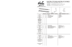
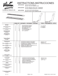
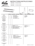
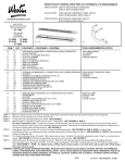
WESTIN WARRANTY
TWELVE MONTH WARRANTY - FOR DRIVING LIGHTS
Westin Automotive Products, Inc. guarantees the original purchaser of Westin products a twelve-month warranty from the date of original purchase against manufacturer defects in materials, workmanship and finish
under normal use excluding damage resulting from road hazards such as gravel or other debris, product misuse, improper installation, impairments from accidents, product modifications or product neglect. This twelvemonth warranty applies only to new products and is limited to the repair or replacement of Westin products. Warranty does not include electrical components or light bulb replacement, costs of removal, installation, labor,
freight, inconvenience or consequential damages. Original purchaser must return defective merchandise, along with the purchase receipt, to the original place of purchase.
THREE YEAR WARRANTY - FOR BED X-TENDERS, BILLET GRILLE, FEY REAR BUMPERS, ROOF RACK PRODUCTS, POWDERCOATED STEEL AND CHROME PLATED STEEL SIGNATURE SERIES STEP
BARS
Westin Automotive Products, Inc. guarantees the original purchaser of Westin products a three-year warranty from the date of original purchase against manufacturer defects in materials, workmanship and finish under
normal use excluding damage resulting from road hazards such as gravel or other debris, product misuse, improper installation, impairments from accidents, product modifications or product neglect. This three-year
warranty applies only to new products and is limited to the repair or replacement of Westin products. Warranty does not include electrical components or light bulb replacement, costs of removal, installation, labor,
freight, inconvenience or consequential damages. Original purchaser must return defective merchandise, along with the purchase receipt, to the original place of purchase.
FIVE YEAR WARRANTY - FOR ALLOY FUEL DOORS, MOLDED STEP BOARDS, SURE GRIP RUNNING BOARDS, POWDERCOATED STEEL AND CHROME PLATED STEEL FRONT END PROTECTION, AND
TAIL LIGHT GUARDS.
Westin Automotive Products, Inc. guarantees the original purchaser of Westin products a five-year warranty from the date of original purchase against manufacturer defects in materials, workmanship and finish under
normal use excluding damage resulting from road hazards such as gravel or other debris, product misuse, improper installation, impairments from accidents, product modifications or product neglect. This five-year
warranty applies only to new products and is limited to the repair or replacement of Westin products. Warranty does not include electrical components or light bulb replacement, costs of removal, installation, labor,
freight, inconvenience or consequential damages. Original purchaser must return defective merchandise, along with the purchase receipt, to the original place of purchase.
LIFETIME WARRANTY - FOR ALL STAINLESS STEEL (CPS) PRODUCTS, POLISHED STAINLESS SIGNATURE SERIES STEP BARS AND OVAL TUBE STEP BARS
Westin Automotive Products, Inc. guarantees the original purchaser of Platinum Series Step Bars, CPS Safari Light Bars, CPS Bull Bars, CPS Tail Light Guards, Sportsman CPS Grille Guards, Aluminum Oval Step Bars
and Polished Stainless Signature Series Step Bars a lifetime warranty against manufacturer defects in materials, workmanship and finish under normal use excluding damage resulting from road hazards such as gravel
or other debris, product misuse, improper installation, impairments from accidents, product modifications or product neglect. This lifetime warranty applies only to new products and is limited to the repair or replacement
of Westin products. Warranty does not include electrical components or light bulb replacement, costs of removal, installation, labor, freight, inconvenience or consequential damages. Original purchaser must return
GARANTÍA
DE CINCO AÑOS
PARA
defective merchandise,
along
with the purchase receipt, to the original place of purchase.
FINISH PROTECTION
Westin products have a high quality finish that must be cared for like any other exposed finish on the vehicle. Protect the finish with a non-abrasive automotive wax (e.g. Pure Carnauba) on a regular basis. The use of
any soap, polish or wax that contains an abrasive is detrimental, as the compounds scratch the finish and open it to corrosion.
DISCLAIMER FOR WESTIN PRODUCTS
Buyer assumes all risk and liability whatsoever from the installation and use of Westin products. Westin products are sold as appearance accessories and should not be relied upon as protection for the vehicle or
occupants in the event of a collision or roll over. Vehicles equipped with a supplemental restraints system (air bags) deployed by impact should not be modified by any aftermarket Grille Guard, Push Bar, Light Bar or
Bull Bar without first consulting the vehicle manufacturer. Westin automotive Products, Inc. Assumes no liability for injury, loss, incidental or consequential damages in the event of an accident.
INSTRUCTIONS-INSTRUCCIONES
APPLICATION: 1997-04 S-BLAZER/JIMMY/EXT. CAB P/U, CC
APLICACIÓN:
S-BLAZER/JIMMY/EXT. CAB P/U, CC P/U, MOD. 1997-04
APPLICATION:
1997-04 S-BLAZER/JIMMY/EXT. CAB P/U, CC P/U
AUTOMOTIVE PRODUCTS, INC.
1 (8X)
ITEM QTY CONTENTS - CONTENIDO - CONTENU
Mount Kit
#27-1105
Lighted Step Board Kit
#27-0015
#27-0005
Unlighted Step Board Kit
#27-0010
#27-0000
Brushed Aluminum
Running Board Kit
#27-6120, 27-6130
Black Aluminum
Running Board Kit
#27-6135, 27-6125
2 (8X)
TOOLS - HERRAMIENTA - OUTILS
1
2
3
4
5
6
7
8
8
24
16
16
64
40
BRACKET
SUPPORT PLATES
5/16” X 3/4” HEX HEAD BOLTS
1/4 SELF DRILLING SCREW
5/16” SQUARE HEAD BOLT
5/16” FLAT WASHER
5/16” LOCK NUT
7/16” SOCKET
1/2” WRENCH
5/16” DRILL BIT
SOCKET ADAPTER
1/2” SOCKET
1/8” DRILL BIT
DRILL
1
2
3
4
5
6
7
8
8
24
16
16
64
40
PIEZA DE SUJECIÓN
PLACAS DE SOPORTE
PERNOS HEXAGONALES DE 5/16” X 3/4”
TORNILLO AUTOPERFORANTE DE 1/4”
PERNOS CON CABEZA CUADRADA DE 5/16”
ARANDELAS PLANAS DE 5/16”
TUERCA A PRESIÓN DE 5/16”
DADO DE 7/16”
LLAVE DE TUERCAS DE 1/2”
BROCA, PARA TALADRO DE 5/16”
ADAPTADOR DE DADO
DADO DE 1/2”
BROCA, PARA TALADRO DE 1/8”
TALADRO
1
2
3
4
5
6
7
8
8
24
16
16
64
40
SUPPORT
PLAQUES DE SUPPORT
5/16 po X 3/4 poBOULON A TETE HEXAGONALE
VIS AUTOPERCEUSE 1/4 po
BOULON A TETE CARREE 5/16 po
RONDELLE PLATE DE 5/16 po
ECROU A FREIN 5/16 po
DOUILLE 7/16 po
CLEF 1/2 po
MECHE DE PERCEUSE, 5/16 po
SUPPORT ADAPTATEUR
DOUILLE 1/2 po
MECHE DE PERCEUSE,1/8 po
PERCEUSE
Aluminum Running
Board Light Kit
#27-6000
Equipo de montaje
#27-1105
Equipo de estribos con faros
#27-0015
#27-0005
Equipo de estribos sin faros
#27-0010
#27-0000
Aluminio pulido
Equipo de estribos deslizantes
#27-6120, 27-6130
Aluminio negro
Equipo de estribos
#27-6135, 27-6125
Equipo de estribos
deslizantes de aluminio, con faros
#27-6000
Jeu de montage
#27-1105
Barre de frottement illuminé
#27-0015
#27-0005
Ensemble de barre de frottement
#27-0010
#27-0000
Ensemble de barre de frottement
en aluminium brossé
#27-6120, 27-6130
Ensemble de barre de frottement
en Aluminium noir
#27-6135, 27-6125
Ensemble de barre de frottement
en aluminiumilluminé
#27-6000
60-2178 REVISION D
ECO 1608
PAGE 1 0F 3
00005896 Rev C 4/20/06
STEP 1.
Remove contents from box and check for damage. Verify all parts are present. Read and understand instructions before beginning.
NOTE: FOR PICKUP, ONLY 6 BRACKETS ARE REQUIRED.
STEP 2.
Drill 5/16” holes as shown (See Figure 1).
STEP 3.
Attach support brackets as shown. Hand tighten (See Figure 2 & 3).
STEP 4.
Attach mounting brackets as shown. Hand tighten (See Figure 4 & 5).
STEP 5.
Insert square head bolts as shown (4 per slot, 8 per Step board/Running board) (See Figure 7 and 8). NOTE: For lighted Step board/Running board, run wiring
harness prior to attaching step board to brackets (Refer to Step 8) (See Figure 7, 8 & 11). Run longer wire harness on passenger side.
STEP 6.
For Aluminum Running boards, if desired, slide closure strip as shown. Set lights (if included) in appropriate location. Attach to running board as shown (See Figure 6). Drill
hole through plastic strip and run wires as shown (See Figure 9).
STEP 7.
Attach Step board / Running board to brackets as shown. Align and tighten all hardware. NOTE: For lighted version of Step board, remove plastic cover from each end of under side of Step board. Proceed to Steps 8-9.
WARNING: INSTALLING LIGHT HARNESS REQUIRES SPLICING INTO VEHICLES ELECTRICAL SYSTEM. WESTIN RECOMMENDS USING A PROFESSIONAL
FOR THIS INSTALLATION. NOTE: AVOID AREAS OF EXCESSIVE HEAT, VIBRATION, PINCH OR ROTATION WHEN SECURING HARNESS TO VEHICLE.
CAUTION: ALWAYS USE A FUSED(+) POSITIVE SUPPLY SOURCE. UNDERCOAT SEAL FOR HARSH WEATHER.
HINT: Step boards: For Longevity, check rubber seals before installation. Rubber grommets around red and blue wires going into rear sockets, should be inserted and
recessed about 1/4”. NOTE: Remove bulbs and apply white grease into sockets and replace bulbs. Apply RTV Silicone where lights go into socket. Install lights
and run wire loom as shown (See Figure 8). For Aluminum Running board, run wire loom down center as shown (See Figure 7).
Determine whether your vehicle has a positive or negative switching courtesy system or an auxiliary light source (most Fords). Obtain an accurate wiring diagram for your vehicle's courtesy light system.
STEP 8.
For Positive and negative switching:
Locate a pass-through point (usually under carpet at driver side door sill) for the wire harness (see figure 11). Locate main courtesy wire (usually wire lead to dome light). NOTE: If you do not use
the main courtesy wire, lights will only function when one door is open. Route wire harness so that the 2 female connections (from step board) are nearest to pass thru point.*Connect opposite
Step board lead to either connection. Connect the splicing lead to remaining female socket and route one wire thru pass thru point.
VERY IMPORTANT - Double check that your system has positive or negative switching.
For positive switching only:
connect positive wire to main courtesy system, (usually wire lead to dome light). TEST CONTINUITY BEFORE CONNECTING BY OPENING AND CLOSING ALL DOORS. Ground remaining wire.
For negative switching only:
Connect negative wire to main courtesy system, (usually wire lead to dome light but sometimes from dome light to courtesy ECU). TEST GROUND CONTINUITY BEFORE CONNECTING BY
OPENING AND CLOSING ALL DOORS. Connect remaining wire to battery using a 5A fuse.
Auxiliary Light source:
Locate auxiliary light source connection under vehicle (usually attached to back side of front or rear fender well (refer to vehicles owners manual) (see figure 11). TEST SOURCE BEFORE
CONNECTING. Connect splicing leads to aux light source. test step board lights for proper function by opening and closing doors.
**Be sure that you have not routed any wires near moving parts (i.e.. driveshaft) or near any heat generating source (i.e.. transmission, engine, exhaust).
STEP 9.
Under-coat Step board/Running board, brackets and electrical wires, connections and lenses for harsh weather conditions. Reinstall plastic cover on underside of Step boards. INSTALLATION IS COMPLETE.
FINISH PROTECTION
Westin products have a high quality finish that must be cared for like any other exposed finish on the vehicle. Protect the finish with a non-abrasive automotive wax, (e.g. Pure Carnauba) on a regular basis. The use of any soap,
polish or wax that contains an abrasive is detrimental, as the compounds scratch the finish and open it to corrosion.
PASO 1.
Retire el contenido de la caja y verifique que ninguna pieza se haya dañado. Verifique que no falte ninguna pieza. Lea las instrucciones completamente antes de comenzar.
NOTA: PARA PICKUP, SE NECESITAN SÓLO 6 SOPORTES.
PASO 2.
Perfore agujeros de 5/16” como se muestra (vea la figura 1).
PASO 3.
Instale los soportes de apoyo como se muestra. Apriete con la mano (vea la figura 2 & 3).
PASO 4.
Instale los soportes de montaje como se muestra. Apriete con la mano (Vea las figuras 4 & 5).
PASO 5.
Inserte los pernos con cabeza cuadrada como se muestra (4 por ranura, 8 por estribo) (vea las figuras 7 y 8). NOTA: Para los estribos/estribos deslizantes con faros, pase el arnés de cables antes de instalar el estribo sobre los
soportes (consulte el paso 8) (vea las figuras 7, 8 & 11 ). Pase el arnés de cables más largo por el lado del acompañante.
PASO 6.
Para estribos deslizantes de aluminio, si deseado, deslice la banda de cierre como se muestra. Ajuste los faros (si están incluidos) en la ubicación correcta. Instale los estribos como se muestra (vea la figura 6). Haga una
perforación en la banda de plástico y pase los cables como se muestra (vea las figuras 9).
PASO 7.
Instale el estribo sobre los soportes como se muestra. Alinee y apriete con la mano. NOTA: Para la versión de estribos con faros, retire la cubierta de plástico de cada extremo en la parte inferior del estribo. Continúe con
los pasos 8 y 9.
ADVERTENCIA: LA INSTALACIÓN DEL ARNÉS DE LOS FAROS REQUIERE CONEXIÓN AL SISTEMA ELÉCTRICO DEL VEHÍCULO. WESTIN RECOMIENDA DEJAR LA INSTALACIÓN EN MANOS DE UN PROFESIONAL. NOTA:
EVITE ÁREAS CON EXCESO DE CALOR, VIBRACIÓN, PRESIÓN O ROTACIÓN AL INSTALAR EL ARNÉS EN EL VEHÍCULO.
PRECAUCIÓN: SIEMPRE USE UNA FUENTE DE ALIMENTACIÓN ELÉCTRICA POSITIVA (+) COMBINADA APLIQUE UN SELLADO DE HULE PARA CONDICIONES CLIMÁTICAS ADVERSAS.
SUGERENCIA: Estribos: Para una mayor duración, verifique los sellos de hule antes de la instalación. Los tapones de hule que rodean los cables rojos y azules que se introducen en los tomas traseros, deben introducirse y embutirse a
aproximadamente ¼”. NOTA: Retire los focos y aplique grasa blanca en los tomas, y vuelva a colocar los focos. Aplique silicona RTV al introducir los focos en los tomas. Instale los faros y pase el tubo de cables como se muestra
(vea la figura 8). Para los estribos deslizantes de aluminio, pase el tubo de cables por debajo del centro como se muestra (vea la figura 7).
PASO 8.
Determine si su vehículo tiene un sistema de luz de cortesía de interruptor positivo o negativo, o una fuente de luz auxiliar (la mayoría de los modelos de Ford). Obtenga un plano preciso del
Cableado del sistema de luces de cortesía de su vehículo.
Para interruptores positivos y negativos:
Identifique un punto de paso (generalmente debajo del tapete del umbral de la puerta del lado del conductor) para el arnés de cables (vea la figura 11). Identifique el cable principal del sistema de las luces de cortesía
(generalmente se provee un conductor a la luz del techo). NOTA: Si no usa el cable principal de las luces de cortesía, las luces sólo funcionarán cuando la puerta esté abierta. Pase el arnés de cables de modo que las dos
conexiones hembras (del estribo) queden más próximas al punto de paso. *Conecte el conductor del estribo opuesto a cualquier conexión. Conecte el cable de conexión al toma hembra que queda libre y atraviese un cable por el
punto de paso.
MUY IMPORTANTE: Vuelva a comprobar si su sistema tiene un interruptor positivo o negativo.
Para interruptor positivo únicamente:
Conecte el cable positivo al sistema principal de las luces de cortesía (generalmente se provee un conductor a la luz del techo). ABRA Y CIERRE TODAS LAS PUERTAS PARA COMPROBAR LA CONTINUIDAD ANTES DE
REALIZAR LA CONEXIÓN. Aterrice el cable restante.
Para interruptor negativo únicamente:
Conecte el cable negativo al sistema principal de luces de cortesía (generalmente, el cable está conectado a la luz del techo, pero a veces la conexión va desde la luz del techo a la unidad de control eléctrico de la luz de cortesía).
ABRA Y CIERRE TODAS LAS PUERTAS PARA COMPROBAR QUE EL SISTEMA CONTINÚE
ATERRIZADO ANTES DE REALIZAR LA CONEXIÓN. Conecte el cable restante a la batería con un fusil de 5 A.
Fuente de luz auxiliar:
Identifique la conexión de la fuente de luz auxiliar debajo del vehículo, que generalmente está instalada en la parte posterior del salpicadero delantero o trasero (consulte el manual del propietario - vea la figura 11). COMPRUEBE
LA FUENTE ANTES
DE REALIZAR LA CONEXIÓN. Conecte el cable de conexión a la fuente de luz auxiliar. Abra y cierre las puertas para comprobar el funcionamiento adecuado de las luces del estribo.
**Asegúrese de no pasar ningún cable cerca de piezas móviles (por ejemplo, el eje del motor) o cerca de ninguna fuente de generación de calor (por ej., transmisión, motor, escape).
PASO 9.
Aplique un sellado de hule a los estribos, soportes y cables eléctricos, conexiones y lentes para protegerlos de condiciones climáticas adversas. Vuelva a instalar la cubierta de plástico en la parte inferior de los estribos. LA
INSTALACIÓN ESTÁ COMPLETA.
(VERIFY LOCATIONS BEFORE DRILLING AND FINAL ATTACHMENT.)
FIGURE 1
FIGURA 1
BLAZER/JIMMY
43”
FORWARD
DELANTERA
AVANT
11”
26”
PAGE 2 0F 3
00005896 Rev C 4/20/06
EXTENDED CAB PICKUP
26”
11”
FORWARD
DELANTERA
AVANT
5/16”
43”
11”
55”
4
FORWARD
DELANTERA
AVANT
55”
35”
35”
11”
63”
D
AR A
RW ER
FO ANT
L
DE NT
AVA
6
FIGURE 2
FIGURA 2
2
3
2
FORWARD
DELANTERA
AVANT
3
1
6
2
FIGURE 3
FIGURA 3
7
6
FIGURE 4
FIGURA 4
FIGURE 5
FIGURA 5
1
5
5
FIGURE 6
FIGURA 6
FIGURE 7
FIGURA 7
FIGURE 8
FIGURA 8
AUXILIARY LIGHT SOURCE (IF EQUIPPED)
FUENTE DE LUZ AUXILIAR (SI ESTÁ INCLUIDA
SOURCE DE LUMIERE AUXILIAIRE (SI EQUIPE)
ETAPE 1.
Enlevez le contenu de la boîte et vérifiez pour tout dommage. Vérifiez que toutes les pièces y sont. Lisez complètement les instructions avant de commencer.
NOTA : POUR LA CAMIONETTE, SEULEMENT 6 SUPPORTS SONT REQUIS
ETAPE 2.
Percez des trous 5/16 po tel qu'illustré (voir figure 1).
ETAPE 3.
Montez les supports tel qu'illustré. Serrez à main (Voir Figure 2 & 3).
ETAPE 4.
Montez les supports de montage tel qu'illustré. Serrez à main (Voir Figure 4 & 5).
ETAPE 5.
Insérez les boulons à tête carrée tel qu'illustré (4 par fente, 8 par marche-pieds/barre de frottement) (voir figure 7 et 8). NOTA : Pour le marche-pieds/barre de frottement illuminée, faites passer le faisceau de câblage avant de
fixer le marche-pieds aux supports (voir étape 8) (voir figure 7, 8 & 11 ). Faites passer le faisceau de câblage le plus long du côté passager.
ETAPE 6.
Pour les barres de frottement en aluminium, si désiré, faites glisser la patte de fermeture tel qu'illustré. Placez les lumières (si incluses) dans les endroits appropriés. Fixez à la barre de frottement tel qu'illustré. (voir figure 6).
Percez un trou dans le plastique et faites passer les câbles tel qu'illustré (voir figure 9).
ETAPE 7.
Montez le marche-pied / la barre de frottement aux supports tel qu'illustré. Alignez et serrez). NOTA : Pour la barre de frottement illuminée, retirez le couvercle de plastique de chaque bout de la face inférieure de la barre. Passez
aux étapes 8 et 9.
MISE EN GARDE: L'INSTALLATION DU FAISCEAU DE CÂBLAGE NÉCESSITE L'ÉPISSAGE DU SYSTÈME ÉLECTRIQUE DU VÉHICULE. WESTIN RECOMMANDE QUE L'INSTALLATION SOIT EFFECTUEE PAR UN
PROFESSIONNEL. NOTA : ÉVITEZ LES ZONES DE CHALEUR INTENSE, LES VIBRATIONS, LE PINCEMENT OU LA ROTATION LORS DU MONTAGE DU FAISCEAU AU VEHICULE.
ATTENTION TOUJOURS UTILISER UNE SOURCE D'ALIMENTATION POSITIVE PROTEGEE PAR UN FUSIBLE (+) ENDUIRE LA BAGUE D'UN PRODUIT D'ETANCHEITE POUR LES CLIMATS SEVERES
ASTUCE :
Barre de frottement : Pour une longue vie de service, vérifiez les joints d'étanchéité en caoutchouc avant la repose. Les passe-fils autour des fils rouges et bleus passant dans les douilles arrière, doivent être insérés et enfoncés
environ 1/4 po. NOTA : Retirez les ampoules et appliquez une couche de graisse blanche dans les douilles et reposez les ampoules. Appliquez de la silicone RTV là où l'ampoule va dans la douille. Installez les lumières et la gaine
isolante tel qu'illustré (voir figure 8). Pour la barre de frottement en aluminium, posez la gaine isolante le long du centre tel qu'illustré (voir figure 7).
ETAPE 8.
Établissez si votre véhicule est muni d'un système d'accueil négatif ou positif ou une source d'illumination auxiliaire (la majorité des Ford). Obtenez le bon schéma de câblage pour le système
de lampe d'accueil de votre véhicule.
Pour commutation négative et positive :
Situez le passe-câble (normalement sous le tapis aux pieds du chauffeur) pour le faisceau de câblage (voir figure 11). Situez le fil principal du système d'accueil (habituellement le fil du plafonnier). REMARQUE : Si vous n'utilisez
pas
le fil principal de la lampe d'accueil, les lampes ne fonctionneront que lorsqu'une porte est ouverte. Posez le faisceau de câblage de façon à ce que les deux connexions femelles (du marche-pieds) se trouvent le plus près du
passe-câble.
*Branchez les fils de l'autre marche-pieds à chaque bout. Branchez le fil d'épissure à la douille femelle restante et passez un fil dans le passe-câble.
TRÈS IMPORTANT Vérifiez que votre système a un système de commutation positif ou négatif.
Pour la commutation positive seulement :
Branchez le fil positif au système d'accueil principal (habituellement le fil du plafonnier). VÉRIFIEZ LA CONTINUITÉ AVANT DE CONNECTER EN OUVRANT ET REFERMANT TOUTES LES PORTES. Mettre à la masse le fil
restant.
Pour la commutation négative seulement :
Branchez le fil négatif au système d'accueil principal (habituellement le fil mène au plafonnier mais parfois le fil va du plafonnier à l'unité de contrôle de la lampe d'accueil). VÉRIFIEZ LA CONTINUITÉ DE LA MASSE AVANT DE
CONNECTER EN OUVRANT ET REFERMANT TOUTES LES PORTES. Branchez le fil restant à la batterie. Utilisez un fusible 5A.
Source d'illumination auxiliaire :
Situez la connexion de source auxiliaire de lumière sous le véhicule (normalement fixé à la face arrière du compartiment d'aile avant ou arrière) (consultez le manuel d'utilisateur du véhicule) (voir figure 11). TESTEZ LA SOURCE
AVANT DE CONNECTER. Branchez les fils d'épissure à la source aux. de lumière. Testez le bon fonctionnement des lumières du marche-pieds en ouvrant et refermant les portes.
** Assurez-vous de ne pas placer les fils près des pièces mobiles (c'est-à-dire la ligne d'arbre) ou de toute source de chaleur (c'est-à-dire la transmission, le moteur, l'échappement).
ETAPE 9.
Appliquez un enduit de protection sur le dessous de marche-pieds / de la barre de frottement, les supports et fils électriques, les connexions et lentilles pour les climats sévères. Reposez le couvercle de plastique sur le dessous
de la barre de frottement. L'INSTALLATION EST TERMINEE.
ECO 1608
6
63”
PROTECCIÓN DEL ACABADO
Los productos Westin tienen un acabado de alta calidad que requiere del mismo cuidado que cualquier otro acabado expuesto del vehículo. Proteja el acabado con una cera no abrasiva para automóviles (por ejemplo, Pure
Carnauba) regularmente. El uso de cualquier jabón, pulidor o cera que contenga un abrasivo es nocivo, dado que los componentes rayan el acabado y lo exponen a la corrosión.
PROTECTION DE LA FINISSION
Les produits Westin ont une finission de haute qualité qui requiert des soins, comme toute autre finission du véhicule exposée aux éléments. Protégez la finission à l’aide d’une cire non-abrasive (par exemple, Pure Carnauba) de façon
régulière. L’usage de tout savon, pâte à polir ou cire contenant un abrasif est nuisible, puisque les composantes strient la finission et la laissent vulnérable à la corrosion.
7
D
AR A
RW ER
FO ANT
L
DE N T
AVA
RED
ROJO
ROUGE
FIGURE 9
FIGURA 9
1 ERUGIF
BLACK
NEGRO
NOIR
FORWARD
DELANTERA
AVANT
BLACK
LT BLUE
NEGRO
CELESTE
NOIR
BLEU PALE
10 AMP FUSE
FUSIBLE DE
10 AMPERES
FUSIBLE DE
10 AMPERES
+
-
BLACK WIRE
TO GRND
CABLE NEGRO
A TIERRA
FIL NOIR
A LA MASSE
SPLICE
CONEXIÓN
EPISSURE
RED WIRE
CABLE ROJO
FIL ROUGE
(SEE WIRING INSTRUCTION)
TO INSIDE ACCESS
PARA ACCESO AL INTERIOR (CONSULTE LAS INSTRUCCIONES DE CABLEADO)
VERS L'ACCES INTERIEUR
(VOIR LES INSTRUCTIONS DE CÂBLAGE)
BLACK
NEGRO
NOIR
5
RED
ROJO
ROUGE
FORWARD
DELANTERA
AVANT
6
7
FIGURE 11
FIGURA 11
FIGURE 10
FIGURA 10
ECO 1608
PAGE 3 0F 3
00005896 Rev C 4/20/06