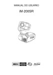
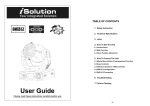
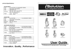
1
TABLE des MATIERES
1. Instructions de sécurité
2. Spécifications Techniques
3. Lampe
4. Comment commander l'unité
4.1 Panneau de commande
4.2 Fonctions principales
4.3 Ajustement de la position initiale
5. Comment contrôler l’unité
5.1 Mode maître/esclave.
5.2 Contrôleur
5.3.1 Contrôleur DMX iSolution
5.4 Configuration DMX512
5.5 Connexion DMX512
6. Dépannage
7. Nettoyage de l’unité
Guide d’utilisation
Lire la notice avant toute utilisation
1
1. Instructions de sécurité
est utilisé dans un but autre que celui pour lequel il a été conçu, s’il n’est pas correctement
monté, utilisé
L’appareil est alimenté par une tension dangereuse 230 V~.
ou n’est pas réparé par une personne habilitée.
Ne faites jamais de modification sur l’appareil si cela n’est pas décrit dans la présente notice
Lorsque l’appareil est définitivement retiré du service, vous devez le déposer dans une usine
et ne faites rien tomber dans les ouïes de ventilation.
de recyclage adaptée pour contribuer à son élimination non polluante.
Une mauvaise manipulation pourrait générer une décharge électrique.
Cet appareil répond à toutes les directives nécessaires de l’Union Européenne et porte donc
ATTENTION
le symbole
Respectez scrupuleusement les points suivants :
Cette lyre est livrée sans lampe. Il est nécessaire d’utiliser une lampe à décharge de type
● Cet appareil n’est conçu que pour une utilisation en intérieur. Protégez-le de tout type de
HMI 575W ou HMQ 575/2.
projections
En aucun cas, vous ne devez utiliser une lampe de type différent !
d’eau, des éclaboussures, d’une humidité élevée et la chaleur (plage de température de
Ne touchez jamais le tube de la lampe avec les doigts ; la sueur et les pellicules grasses sur
fonctionnement autorisée : 0 – 40 °C).
les doigts diminuent la puissance lumineuse de la lampe et se consument.
● Pendant le fonctionnement, la tête chauffe de manière très importante (+ de 85°c). Pour
éviter toute brûlure,
AVERTISSEMENT
ne touchez jamais la tête pendant le fonctionnement; après avoir éteint l’appareil, laissez-la
refroidir quelques minutes avant de la toucher.
Avant d’insérer ou retirer la lampe halogène, vous devez impérativement débrancher
● En aucun cas, vous ne devez poser pas d’objet contenant du liquide ou un verre sur
l’appareil du secteur.
l’appareil.
● Pendant le fonctionnement, la lampe est très chaude, vous devez laisser refroidir le boîtier
● Ne faites pas fonctionner l’appareil et débranchez-le immédiatement du secteur lorsque :
et la lampe après toute utilisation et avant tout remplacement (refroidissement pendant 15
1. des dommages apparaissent sur l’appareil, par exemple sur le boîtier, sur la lentille, sur le
minutes au moins).
filtre
● Ne regardez jamais directement, appareil ouvert, vers la lampe à décharge allumée. La
UV ou sur le cordon secteur,
luminosité élevée et le rayonnement UV peuvent causer des dommages aux yeux.
2. après une chute ou un cas similaire, vous avez un doute sur l’état de l’appareil,
● La lampe proposée contient en faible quantité des produits toxiques nocifs pour
3. des défaillances apparaissent.
l’environnement (mercure par exemple). En Europe, il est impératif de la déposer dans une
Dans tous les cas, les dommages doivent être réparés par un technicien spécialisé.
poubelle adéquate.
● Ne débranchez jamais l’appareil en tirant sur le cordon secteur ; retirez toujours le cordon
Dans d’autres pays, vous devez vous reporter aux lois en vigueur.
secteur
● Il convient de remplacer la lampe après au moins 1,25ème de sa durée moyenne de vie car
en tirant la fiche.
une durée d’utilisation croissante augmente de manière significative le risque d’un
● Tout cordon secteur endommagé ne doit être remplacé que par le constructeur ou un
éclatement de la lampe à la suite de modifications de structure du verre quartz.
technicien qualifié.
● Après un éclatement de la lampe pendant le fonctionnement, il est recommandé de quitter
● Pour le transport, saisissez l’appareil uniquement par les poignées. En aucun cas, vous ne
l’environnement
devez le porter par la tête ou par les bras.
immédiat de la lampe, par précaution, pour éviter toute mise en danger de la santé générée
● Pour nettoyer le boîtier, utilisez un chiffon sec et doux, en aucun cas, de produits chimiques
par la dispersion à l’air libre des vapeurs de mercure; veillez à une aération correcte de la
ou d’eau. Pour la lentille, vous pouvez utiliser des nettoyants pour verres usuels.
pièce.
● Nous déclinons toute responsabilité en cas de dommages matériels ou corporels
résultants si l’appareil
2
3
2. Spécifications Techniques
Installation
La IM 575 SP peut être posée sur une surface fixe et plane. La lyre peut être montée sur une
traverse,
la tête en bas via la plaque de base. Pour la fixation, des clips stables de montage sont
Alimentation
- AC120V ~ 60 Hz ou AC 230/240/250V~50/60Hz
Lampe
- HMI 575W / HMQ 575/2 SFc10-4
Vissez solidement les clips directement dans les filetages M10 ou fixez-le sur les étriers de
Système Optique
- Système optique haute performance
montage livrés dont les boulons, comme indiqué sur le schéma, sont placés dans les
- Lentilles et couleurs dichroïque qualité supérieure
ouvertures prévues sur la plaque de base et verrouillés dans le sens des aiguilles d’une
- Angle d'ouverture : 14°
montre (tournez jusqu’à la butée). Le lieu de montage doit être suffisamment stable et
Shutter/Dimmer
pouvoir supporter une charge de 30 kg au moins par appareil.
- Black out, dimmable de 0~100%
nécessaires.
- vitesse de strob réglable de (1~10 flash par seconde).
IMPORTANT
Roue de couleur
Placez l’appareil de telle sorte que pendant le fonctionnement, la circulation d’air soit
- une rotation rapide de la roue de couleur donne un effet rainbow.
suffisante.
Roues de Gobo
● L’appareil doit être placé à une distance minimale de 50 cm des surfaces voisines.
- une roue de gobo comprend 9 gobos plus ouverture complète
● Les ouïes de ventilation sur le boîtier ne doivent en aucun cas être obturées.
- la roue de gobo comprend 7 gobos interchangeable plus ouverture complète
● Veillez impérativement à laisser une distance suffisante avec des matériaux facilement
- une vibration de la roue de Gobos donne un effet shaking.
inflammables
Roue d’effet
ou sensibles à la chaleur.
- Prisme/Rotation de Prisme
- la roue de couleur comprend 9 couleurs dichroïques plus le blanc.
Mouvement
- Pan: 540° en 2.8 secondes.
- Tilt: 270° en 1.6 seconde.
Canaux DMX
- Le protocole d’adressage est un DMX 512 standard, permettant un pilotage par toute les
consoles DMX universelle.
16 Canaux:
4
Canal 1 = Pan
Canal 9 = Gobo 2
Canal 2 = Tilt
Canal 10 = Gobo2 Rotation
Canal 3 = Pan/Tilt Speed select
Canal 11 = Prism
Canal 4 = Dimmer
Canal 12 = Prism Rotation
Canal 5 = Shutter/Shaking
Canal 13 = Focus
Canal 6 = Color
Canal 14 = Pan 16 bit
Canal 7 = Iris
Canal 15 = Tilt 16 bit
Canal 8 = Gobo 1
Canal 16 = Reset/Lamp on/off
5
8 Canaux:
intensité lumineuse:
ATTENTION !
Ne dévissez jamais les vis du gobo tournant car le roulement à
Canal 1 = Pan
billes sera automatiquement ouvert !
Canal 2 = Tilt
3.Lampe
Canal 3 = Shutter
En cas de remplacement de la lampe ou de l'entretien, n'ouvrez pas
Canal 4 = Gobo
le montage dans un délai de 15 minutes jusqu'à ce que l'unité soit
Canal 5 = Color
refroidit
Canal 6 = Gobo Rotation/Iris
Canal 7 = Prism/Prism
Rotation/Dimmer
En raison de sa pression interne élevée, il pourrait y avoir des risques d’éclatement des
Canal 8 = Focus
lampes à décharges pendant l’opération.
Dimensions: 427 x 478 x 369 mm (L x l x H)
Poids: 28,5 kg
La lampe émet un rayonnement UV intense qui est nocif aux yeux et à la peau.
La luminance élevée de l'arc peut endommager considérablement la rétine si des regards
sont portés de façon direct sur la lampe.
Type de lampe : HMI 575W / HMQ 575/2
2.1 Insé
érer / Echanger un gobo rotatif
SFc10-4
1. Coupez toujours l'alimentation principal et ne manipulez jamais la lampe ou les lumières
quand l’unité est chaude.
2. Ne touchez pas l'ampoule avec les mains nues. Si ceci se produit, nettoyez la lampe avec
DANGER !
Installez les gobos avec l’unité arrêtée.
Débranchez l’alimentation avant de changer des gobos!
de l'alcool dénaturé et essuyez-là avec un tissu non pelucheux avant installation.
3. La lampe produit du rayonnement UV. N'actionnez jamais la lampe sans l’armature
appropriée.
4. En brûlant, la lampe fonctionne à la haute pression et il y a un léger risque de rupture de
Ouvrez le capot en desserrant les vis d'attaches sur les côtés du capot.
tube d'arc. Le risque augmente avec l'âge.
Si vous souhaitez employer d'autres formes et modèles de gobos, ou si les gobos doivent
N'utilisez pas la lampe plus longtemps que sa vie indiquée.
être échangés, enlevez l'anneau de fixation avec un outil approprié. Enlevez le gobo et
5. Assurez-vous que la lampe est située au centre du réflecteur pour un effet optimal.
insérez le nouveau gobo. Remettez l’anneau de fixation à l'avant du gobo.
6
7
4.2 Fonctions principales
4. Comment commander l’unité
Pour choisir des fonctions données, appuyez sur le bouton de MENU jusqu'à ce que la
4.1. Panneau de controle
fonction exigée s’affiche. Choisissez la fonction appuyé sur ENTER l’affichage clignotera.
Utilisation VERS LE BAS et vers le HAUT pour changer de mode. Une fois que le mode
exigé a été choisi,
appuyez sur le bouton de ENTER
pour installer, il reviendra automatiquement aux
fonctions principales après 8 s de non affectation. Pour aller de nouveau aux fonctions
pressez le Bouton de MENU. Les fonctions principales s’affichent comme ci dessous :
Affichage
Pour montrer le divers menu et les fonctions choisies.
LED
DMX
On
Entrée DMX présente
MASTER
On
Mode Maître activé
SLAVE
On
Mode esclave activé
SOUND
Clignotante
Mode audio active
Bouton
MENU
Pour choisir les différentes fonctions
DOWN
Pour monter dans les fonctions
UP
Pour descendre dans les fonctions
ENTER
Pour confirmer les fonctions
Entrée contrôleur à distance
Pour relier une télécommande entrée Jack 6.35mm
Sensibilité
accès au mode DMX 512
Pour ajuster la sensibilité du micro.
Microphone
Reçoit le signal audio pour l'activation sonore.
Appuyez sur le bouton de MENU jusqu'à se que s’affiche le mode
. Appuyé sur
ENTER le bouton et l'affichage clignoteront. APPUYER SUR UP ou DOWN pour afficher le
bon canal DMX.
Entrée-sortie de DMX
Pour le lien DMX512, utilisez des câbles DMX blindés avec prise XLR 3 broches.
Une fois l'adresse choisie, appuyer sur le bouton ENTER, si vous n’avez pas validé au bout
de 8 secondes la machine revient au mode automatique.
8
9
MODE CANAUX
Inversion Pan
Appuyez sur le bouton de MENU jusqu'à se que s’affiche le mode
ENTER POUR VALIDER. APPUYER SUR UP ou DOWN pour afficher
. Appuyez sur
(16 Canaux)
ou
(8 Canaux). appuyer sur le bouton ENTER, si vous n’avez pas validé au bout
de 8 secondes la machine revient au mode automatique.
Mode Show
Appuyez sur le bouton de MENU jusqu'à ce que
s’affiche. Appuyez sur ENTER
l'affichage clignoteront. Naviguez avec les bouton UP et DOWN pour choisir
(normal) ou
(inversion PAN). Une fois que le mode a été choisi, appuyez sur le
bouton ENTER.
Tilt Inversion
Appuyez sur le bouton de MENU jusqu'à quand
clignote. Employez UP et DOWN pour choisir
. Appuyez sur ENTER l'affichage
(show 1) ou
(show 2) ou
(show 3) ou
(show 4). Une fois que le mode a été choisi, appuyez sur
ENTER pour VALIDER ou le retour à l’état précédent se fera automatiquement après 8
Appuyez sur le bouton de MENU jusqu'à ce que
s’affiche. Appuyez sur ENTER
l'affichage clignoteront. Naviguez avec les bouton UP et DOWN pour choisir
(normal) ou
bouton ENTER.
(inversion TILT). Une fois que le mode a été choisi, appuyez sur le
secondes. Pou un retour appuyez sur MENU
- le montage est placé au sol. Angle 210° de mouv ement d'inclinaison.
- le montage est fixe sous plafond. Angle 90° de mouvement d'inclinaison.
- le montage est placé en face, l’unité projette toujours dans la direction de
l'assistance ; c.-à-d. devant. Angle de mouvement de PAN(gauche à droite) :
160°.
Angle de mouvement d'inclinaison : 90° (60° au-dessus d'horizon ; 30°
au-dessous d'horizon.)
d'inclinaison TILT : 90° (verticalement, 75° avant ; 15° arrière).
(Led on) ou
(Led off). Une fois que le mode a été choisi, appuyez sur
secondes. Pou un retour appuyez sur MENU.
Inversion Display
Appuyez sur le bouton de MENU jusqu'à ce que
s’affiche. Appuyez sur ENTER le
bouton et l'affichage clignoteront. Naviguez avec les bouton UP et DOWN pour choisir
Mode esclave
apparaisse sur l'affichage.
Appuyez sur le bouton de MENU jusqu'à ce que
Appuyez sur ENTER l'affichage clignote. Naviguez avec les bouton UP et DOWN pour
(normal) ou
Appuyez sur le bouton de MENU jusqu'à ce que
s’affiche. Appuyez sur ENTER le
bouton et l'affichage clignoteront. Naviguez avec les bouton UP et DOWN pour choisir
ENTER pour VALIDER ou le retour à l’état précédent se fera automatiquement après 8
- le montage est fixe sous plafond. L’unité projette principalement de face.
Angle de mouvement de PAN (gauche à droite) :160°. Angle de mouvement
choisir
Afficheur à LED
(2 light show). Une fois que le mode a été choisi,
appuyez sur ENTER pour VALIDER ou le retour à l’état précédent se fera automatiquement
après 8 secondes. Pou un retour appuyez sur MENU
(inversion du display affichage vers le sol) ou
(normal affichage vers le
plafond). Une fois que le mode a été choisi, appuyez sur le bouton ENTER.
ajustement de focus pour les gobos 1
s’affiche. Appuyez sur ENTER,
Appuyez sur le bouton de MENU jusqu'à ce que
l’unité va se mettre automatiquement sur un TILT de 135°, vous pouvez passer sur un TILT
à 45° et des PAN à 0°, 90°, 180°, 270°, à chaque fo
Mode Blackout
is vous devez appuyez sur le bouton
ENTER. Pour ajuster votre focus, utilisez les touches DOWN et UP. Pour revenir au menu
Appuyez sur le bouton de MENU jusqu'à ce que
s’affiche. Appuyer sur ENTER le
bouton et l'affichage clignoteront. Naviguez avec les bouton UP et DOWN pour choisir
(yes blackout) ou
(no blackout). Une fois que le mode a été choisi,
appuyez sur ENTER pour VALIDER ou le retour à l’état précédent se fera automatiquement
après 8 secondes. Pou un retour appuyez sur MENU
10
appuyez sur la touche MENU.
ajustement de focus pour les gobos 2
Appuyez sur le bouton de MENU jusqu'à ce que
s’affiche. Appuyez sur ENTER,
l’unité va se mettre automatiquement sur un TILT de 135°, vous pouvez passer sur un TILT
11
à 45° et des PAN à 0°, 90°, 180°, 270°, à chaque fo
is vous devez appuyez sur le bouton
ENTER. Pour ajuster votre focus, utilisez les touches DOWN et UP. Pour revenir au menu
DMX Reset: mettez le canal DMX 16 en position 200~209., ainsi tous les canaux de l'unité
retourneront à leur position initiale après un laps de 5 secondes.
4.3 Ajustment de la position initiale
appuyez sur la touche MENU.
Appuyez le bouton MENU
Mode Test
pendant 5 secondes pour entrer dans le mode OFFSET et
ajuster la position initiale, quand vous voulez ajuster les gobos et les couleurs, vous devez
Appuyez sur le bouton de MENU jusqu'à ce que
s’affiche. Appuyez sur ENTER
l'affichage clignoteront. Une fois que le mode a été choisi, appuyez sur le bouton ENTER..
, les fonctions sont alors les suivantes:
allez jusqu’au mode
Pan offset(0~512)
Température ambiante de la lampe
Tilt offset(0~2048)
Appuyez sur le bouton de MENU jusqu'à ce que
s’affiche. Appuyez sur ENTER et
la température de la tête au se trouve la lampe apparaîtra sur l’afficheur. Pour revenir au
Focus Adjust(0~255)
MENU
menu appuyez sur la touche MENU.
Gobo1 offset(-127~127)
compteur de Lampe
Gobo2 offset(-127~127)
Appuyez sur le bouton de MENU jusqu'à ce que
s’affiche. Appuyez sur ENTER
l'affichage clignoteront. Une fois que le mode a été choisi, appuyez sur le bouton ENTER, le
Color offset(-127~127)
temps s’affichera.
Excentrage de PAN
Lampe ON/OFF
Appuyez le bouton MENU
Appuyez sur le bouton de MENU jusqu'à ce que
s’affiche. Appuyez sur ENTER
l'affichage clignoteront. Naviguez avec les bouton UP et DOWN pour choisir
(Lampe on) ou
(Lampe off). Une fois que le mode a été choisi, appuyez sur ENTER
pour VALIDER ou le retour à l’état précédent se fera automatiquement après 8 secondes.
pendant 5 secondes pour entrer dans le menu d’excentrage,
utilisez les boutons DOWN et UP jusqu’à ce que
apparaisse sur l’afficheur.
Appuyez sur ENTER le bouton et l'affichage clignoteront. Utilisez DOWN et UP pour ajuster
la position initiale du PAN. Quand la position estctions OFFSET, pour tout changement
appuyez sur MENU.
Pou un retour appuyez sur MENU.
Tilt offset choisit appuyez sur ENTER pour revenir automatiquement au
Power ON/OFF
fun
Appuyez sur le bouton MENU jusqu'à ce que [insert the symbol] s'affiche. Appuyez sur
Appuyez le bouton MENU pendant 5 secondes pour entrer dans le menu d’excentrage,
ENTER l'affichage clignotera. Naviguez avec les bouton UP et DOWN pour choisir [insert
the symbol] (Power On) ou [insert the symbol] (Power Off). Une fois que le mode a été
utilisez les boutons DOWN et UP jusqu’à ce que
apparaisse sur l’afficheur.
Appuyez sur ENTER le bouton et l'affichage clignoteront. Utilisez DOWN et UP pour ajuster
choisi, appuyez sur ENTER pour valider ou le retour à l’état précédent se fera
la position initiale du TILT. Quand la position est choisit appuyez sur ENTER pour revenir
automatiquement après 8 secondes. Pour un retour appuyez sur MENU.
automatiquement au fonctions OFFSET, pour tout changement appuyez sur MENU, au bout
de 8 secondes un retour automatique se fera vers les fonctions principales.
Reset (redémarrage)
Appuyez sur le bouton de MENU jusqu'à ce que
s’affiche. Appuyez sur ENTER le
bouton et l'affichage clignoteront. Une fois que le mode a été choisi, appuyez sur le bouton
ENTER, l’unité se recalera automatiquement.
12
Focus Adjust
Appuyez le bouton MENU pendant 5 secondes pour entrer dans le menu d’excentrage,
utilisez les boutons DOWN et UP jusqu’à ce que
apparaisse sur l’afficheur.
Appuyez sur ENTER, l’unité va se mettre automatiquement sur un TILT de 135°, vous
13
pouvez passer sur un TILT à 45° et des PAN à 0°, 90 °, 180°, 270°, à chaque fois vous devez
Color offset
appuyez sur le bouton ENTER. Pour ajuster votre focus, utilisez les touches DOWN et UP.
Pour revenir au menu appuyez sur la touche MENU.
Appuyez le bouton MENU pendant 5 secondes pour entrer dans le menu d’excentrage,
utilisez les boutons DOWN et UP jusqu’à ce que
apparaisse sur l’afficheur.
Appuyez sur ENTER le bouton et l'affichage clignoteront. Utilisez DOWN et UP pour ajuster
Dimmer offset
Appuyez sur le bouton MENU pendant 5 secondes pour entrer dans le menu d'excentrage.
la position initiale des couleurs. Quand la position est choisit appuyez sur ENTER pour
. Une
Utilisez les boutons DOWN et UP jusqu'à ce qu'apparaisse sur l'afficheur
fois la couleur sélectionnée, appuyez sur ENTER pour revenir automatiquement au
revenir automatiquement au fonctions OFFSET, pour tout changement appuyez sur MENU,
au bout de 8 secondes un retour automatique se fera vers les fonctions principales.
fonctions OFFSET, pour tout changement appuyez sur MENU, au bout de 8 secondes un
retour automatique se fera vers les fonctions principales.
5. Comment commander l’unité
Vous pouvez actionner l'unité de trois manières :
Gobo1 offset
1. Par fonction intégrée master/slave préprogrammée
Appuyez le bouton MENU pendant 5 secondes pour entrer dans le menu d’excentrage,
2. Par contrôleur simplifié
utilisez les boutons DOWN et UP jusqu’à ce que
apparaisse sur l’afficheur.
Appuyez sur ENTER le bouton et l'affichage clignoteront. Utilisez DOWN et UP pour ajuster
3. Par IL-0824 (référez-vous svp au guide d'utilisateur du contrôleur d'iLead) ou un
la position initiale du GOBO 1. Quand la position est choisit appuyez sur ENTER pour
Aucun besoin d'arrêter l'unité quand vous changez l'adresse de DMX, le nouveau
revenir automatiquement au fonctions OFFSET, pour tout changement appuyez sur MENU,
positionnement d'adresse de DMX sera effectué immédiatement.
au bout de 8 secondes un retour automatique se fera vers les fonctions principales.
Chaque fois que vous allumez l'unité, elle se calera et prendra position et vous pouvez
contrôleur DMX universel.
entendre quelques bruits pendant environ 20 secondes. Ensuite l'unité sera prête à recevoir
Gobo2 offset
le signal de DMX ou à fonctionner en mode autonome avec ces programmes internes.
Appuyez le bouton MENU pendant 5 secondes pour entrer dans le menu d’excentrage,
utilisez les boutons DOWN et UP jusqu’à ce que
apparaisse sur l’afficheur.
Appuyez sur ENTER le bouton et l'affichage clignoteront. Utilisez DOWN et UP pour ajuster
5.1 mode maître / esclave pré programmé
la position initiale du GOBO 2. Quand la position est choisit appuyez sur ENTER pour
revenir automatiquement au fonctions OFFSET, pour tout changement appuyez sur MENU,
Vous pouvez sélectionner le mode blackout
en
(yes blackout) ou
au bout de 8 secondes un retour automatique se fera vers les fonctions principales.
(no blackout) pendant que l'unité est en marche.
R-gobo offset
En liant les unités par un raccordement master/slave, la première unité commandera les
Appuyez le bouton MENU pendant 5 secondes pour entrer dans le menu d’excentrage,
autres unités pour donner un show actif et synchronisé. Cette fonction est bonne quand
vous voulez une utilisation instantanée.
utilisez les boutons DOWN et UP jusqu’à ce que
apparaisse sur l’afficheur. Appuyez
La LED maître sera allumé et la LED sound clignotera en fonction de l’ambiance sonore.
sur ENTER le bouton et l'affichage clignoteront. Utilisez DOWN et UP pour ajuster la
Les autres unités devront être assigné en mode SLAVE (la LED slave s’allumera)
position initiale R-gobo. Quand la position est choisie appuyez sur ENTER pour revenir
choisissez le mode d’utilisation (normale) ou (le mode show 2 … etc.). Vous pouvez
automatiquement au fonctions OFFSET, pour tout changement appuyez sur MENU, au bout
de 8 secondes un retour automatique se fera vers les fonctions principales.
sélectionner
(show 4)
14
(show 1) ou
(show 2) ou
avec le contrôleur.
15
(show 3) ou
2-light show
En
(mode esclave),
signifie un fonctionnement classique et
signifie un deuxième light show. Afin de créer un grand light show, vous pouvez placer
sur la deuxième unité pour obtenir des mouvements contrastés entre eux, même si
vous avez deux unités seulement.
5.3.2 DMX Controller
Un contrôleur universel de DMX pour commander les unités, vous devez placer l'adresse de
DMX de 1 à 512 canaux de sorte que les unités puissent recevoir le signal de DMX.
Appuyez sur le bouton de MENU jusqu'à que
s’affiche. Appuyé sur ENTER le
bouton et l'affichage clignoteront. Naviguez avec les boutons UP et DOWN pour changer
5.2. Easy Controller
l'adresse DMX512.
Une fois que l'adresse a été choisie, appuyez sur ENTER JUSQU A CE QUE L’affichage
La télécommande facile CA 8 est employé seulement dans le mode master/slave.
cesse ou il sera stocker automatiquement 8 secondes plus tard.
En ce branchant sur la prise Jack 6.35 mm de la première unité, vous commanderez tout les
Veuillez vous référer au diagramme suivant pour adresser vos canaux DMX512 pour les 4
autres unités reliées..
premières unités
16 Canaux:
Stand by
Met l’unité en Blackout
Function
Strobe
Mouvement X/Y Durant Selection
1. Color sync. strobeles shows ( Show 1 ~ Gobo/Couleur
Show 4 )
2. Sync. strobe
3. Two-light strobe Voir chapitre 4.2
Mode
Sound 1
(LED off )
Sound 2
(LED
lentement)
Mouvement X/Y
1.Pan position
2.Tilt position
3.Dimmer
First set Master unit,
then set Slave units’
position
8 Canaux :
L'adresse de DMX peut être placée à distance par le contrôleur IL-0824. Aucun besoin de
calculer le DMX canaux de chaque montage dans la chaîne(uniquement en Mode 8 canaux)
Slow/Sound 3 Position/ Latch
(LED clignote vite)
clignote (LED on)
8 Canaux:
5.3.1 iSolution Operation
♦ la liaison DMX permet à l'i Rock et l'i Show d’être piloté ensemble et commandé en même
temps.
♦ l’adresse DMX peut être placée à distance par le contrôleur d'iLead (référez-vous svp au
manuel d'utilisateur du contrôleur d'i Lead). Aucun besoin de calculer les canaux de DMX de
chaque montage dans la chaîne.
♦ la commutation automatique des programmes entre la fonction de DMX et la fonctions
maître/esclave est intégrée.
16
17
Pour la lampe, mettez la valeur de DMX de CH-16 à CH-130-139
Pour désactiver la :lampe, mettez la valeur de DMX de CH-16 à CH 230-239.
5.4. Configuration DMX512
Pour un reset DMX, mettez la valeur DMX de CH-16 à 200-209, l'unité se remettra
à zéro après environ cinq secondes.
18
19
6. Dépannage
5.5. DMX512 Connection
Suive quelques problèmes communs qui peuvent se produire lors du fonctionnement.
Le DMX512 est employé couramment dans la commande intelligente de l'éclairage, avec
Voici certaines
suggestions pour le dépannage facile :
un maximum de 512 canaux.
A. L'unité ne fonctionne pas, aucune lumière et le ventilateur ne fonctionne pas
1. Vérifiez la puissance de relier et le fusible principal.
2. Mesurez la tension de forces sur le connecteur principal.
3. Vérifiez la puissance sur la LED.
B. Ne répondant pas au contrôleur de DMX
1. la LED DMX devrait être allumé. Sinon, le connecteurs du contrôle DMX n’est pas
raccordés correctement.
2. Si la LED DMX est allumé et qu il n’y a aucune réponse au canal, vérifiez les
positionnements d'adresse et
la Polarité du DMX.
3. Si vous avez des problèmes intermittents de signal de DMX, vérifiez les connecteurs de
l’unité défaillante et la précédente.
4. Essayez d'employer un autre contrôleur de DMX.
5. Vérifiez l’absence d’interférence avec des câbles électriques.
1.Si vous employez un contrôleur avec une sortie DMX 5 broches, vous devez employer
des câbles adaptateurs 5/3 broches XLR.
2.les lignes DMX doivent être terminés avec un bouchon de terminaison. Soudez une
résistance de 120 ohms 1/4W la résistance entre la borne 2 (DMX-) et borne 3 (DMX+) dans
un XLR
3 broches ce bouchon devra être raccordé à la sortie DMX de la dernière unité.
3.il n’y a aucun raccordement DMX possible en Y, ceci coupe le signal DMX
4.chaque unité doit avoir une adresse DMX réglée pour recevoir les données envoyées par
le contrôleur.
Le nombre d'adresse est entre 0-511 (habituellement 0 et 1 sont égaux à 1).
5.l’extrémité du système DMX512 devrait être terminée pour réduire les erreurs de signal.
Les branchements XLR
3 broches XLR : Borne 1 : La terre, borne 2 : Signal négatif (-), borne 3 : Signal positif (+)
5 broches XLR : Borne 1 : La terre, borne 2 : Signal négatif (-), borne 3 : Signal positif (+)
C. Quelques unités ne répondent pas au contrôleur facile
1. Vous pouvez avoir une coupure dans le câblage de DMX. Examinez la LED puis assurez
vous de la réponse du signal master/slave de mode.
2. l’Adresse DMX de l’unité est fausse. Placez l'adresse appropriée.
D. Aucune réponse au bruit
1. Assurez vous que l'unité ne reçoit pas le signal DMX.
2. Vérifiez le microphone pour voir s'il est bon en tapotant légèrement dessus.
E. Un des canaux ne fonctionne pas bien
1. Le moteur pas à pas pourrait être endommagé ou le connecteur XLR à la carte est
cassé.
2. L'IC’ d'entraînement du moteur sur la carte pourrait être hors de condition.
F. La lampe coupe par intermittence
1. La lampe ne fonctionne pas bien. Vérifiez si la tension principale n’est pas trop haute ou
20
21
trop basse.
F. Si la courroie de TILT est cassée
2.La température interne peut être trop haute. Vérifiez et remplacez au besoin le
1. Coupez le courant principal.
ventilateur sur la tête.
2. dévissez les vis (A) et enlevé le capot des bras (B).
3. Dévissez les vis (C), les vis (D) et les vis (E) qui fixent le pont.
G. Si la courroie de PAN est cassée
1. Coupez le courant principal.
4. changez la courroie (F). et ajusté sa tension correctement.
2. Dévissez tous les vis (a) et ouvrez le capot du logement de base (b).
Note : si elle est trop serrée elle peut se rompre.
3. Dévissez tous les vis (c) et ouvrez le capot des bras (d).
10. Puis remonter en suivant les procédures du point 3 au point 2.
4. Débranchez tout les fils qui relient les bras à la base.
D
5. Dévissez les vis (e) et enlevez la tête.
F
E
6. Desserrez les vis (f), puis desserrez les vis (G).
7. Changez la courroie (h), mettez la courroie autour de l’axe moteur.
8. revissé les vis (G), installe la nouvelle courroie et ajusté sa tension correctement.
Note : si elle est trop serrée elle peut se rompre.
9. Rebranchez le tout (les fils entre la base et les bras).
A
10. Puis remonter en suivant les procédures du point 5 au point 2.
C
B
C
C
D
C
C
D
A
B
F
B
E
A
H
A
G
22
23
Prêtez attention à la tension de la courroie quand vous l’installez.
7. Nettoyage de l’unité
Le nettoyage des objectifs et/ou des miroirs optiques internes et externes doit être effectué
Veuillez vous référer aux photos ci-dessous:
de façon périodique ceci afin d’optimiser le rendement lumineux. La fréquence de nettoyage
dépend de l'environnement dans lequel l’unité fonctionne : humide, enfumé ou dans un
environnement sale, ces conditions peuvent causer une plus grande accumulation de saleté
sur le système optique de l’unité.
Nettoyez avec un tissu doux en utilisant un liquide de nettoyage pour les vitres.
Séchez toujours les pièces soigneusement.
Nettoyez le système optique externe au moins tous les mois. Nettoyez le système
optique interne au moins tout les 2 mois
F
EC Declaration of Conformity
We declare that our products (lighting equipments) comply with the following
G
specification and bears CE mark in accordance with the provision of the
Photo 1
Electromagnetic Compatibility (EMC) Directive 89/336/EEC.
EN55014-2: 1997 A1:2001, EN61000-4-2: 1995; EN61000-4-3:2002;
EN61000-4-4: 1995; EN61000-4-5: 1995, EN61000-4-6:1996,
EN61000-4-11: 1994.
&
Harmonized Standard
EN60598-1: 2000+ALL:2000+A12:2002
Safety of household and similar electrical appliances
Part 1 : General requirements
Adjust belt tension through loose the screw
24
25
1. Safety Instruction
Please read carefully the instruction, which includes important
information about the installation, usage and maintenance.
WARNING
TABLE OF CONTENTS
Please keep this User Guide for future consultation. If you sell the unit to another user, be
sure that they also receive this instruction booklet.
Unpack and check carefully there is no transportation damage before using the unit.
1. Safety Instruction
Before operating, ensure that the voltage and frequency of power supply match the power
requirements of the unit.
2. Technical Specification
The unit is designed for use with the HMI 575W, HMQ 575/2 lamps. Do not use any other
type of lamp.
3. Lamp
It’s important to ground the yellow/green conductor to earth in order to avoid electric
4. How To Set The Unit
4.1 Control Panel
4.2 Main Function
4.3 Home Position Adjust
The unit is for indoor use only. Use only in a dry location.
shock.
The unit must be installed in a location with adequate ventilation, at least 50cm from
adjacent surfaces. Be sure that no ventilation slots are blocked.
Disconnect main power before fuse/lamp replacement or servicing.
Replace fuse/lamp only with the same type.
5. How To Control The Unit
5.1 Master/Slave Built-In Preprogrammed Function
5.2 Easy Controller
5.3 iSolution Operation / DMX Controller
5.4 DMX 512 Configuration
5.5 DMX 512 Connection
Make sure there are no flammable materials close to the unit while operating, as it is fire
hazard.
Use safety chain when fixes this unit. Don’t handle the unit by taking its head only, but
always by taking its base.
Maximum ambient temperature is Ta : 40℃. Don’t operate it where the temperature is
higher than this.
Unit surface temperature may reach up to 85℃. Don’t touch the housing bare-hand during
6. Troubleshooting
its operation, and allow about 15 minutes to cool down before replacing bulb or serving,
as the unit could be very hot.
In the event of serious operating problem, stop using the unit immediately. Never try to
7. Fixture Cleaning
repair the unit by yourself. Repairs carried out by unskilled people can lead to damage or
malfunction. Please contact the nearest authorized technical assistance center. Always
use the same type spare parts.
Don’t connect the device to any dimmer pack.
Do not touch any wire during operation as high voltage might be causing electric shock.
26
27
Warning
2. Technical Specification
To prevent or reduce the risk of electrical shock or fire, do not expose the unit to rain or
moisture.
Never touch bulb with bare fingers, as it is very hot after using.
Hot lamp explosion hazard. Do not open the unit within five minutes after switching off.
Do not start on the unit without bulb enclosure or housing are damaged.
The housing, the lenses, or the ultraviolet filter must be replaced if they are visibly
Power supply
- AC 120V~60Hz or AC 230/240/250V~50/60Hz
Lamp
- HMI 575W / HMQ 575/2
lamp base:SFc10-4
Optical system
- High efficiency optical system
- High quality optical lens and dichroic colors
damaged.
Do not look directly at the light while the bulb is on.
Caution
There are no user serviceable parts inside the unit. Do not open the housing or attempt any
repairs by yourself. In the unlikely event your unit may require service, please contact your
nearest dealer.
- Beam angle: 14°
Shutter/Dimmer
- Blackout, 0~100 smooth dimming and strobe speed variable(1~10 flashes per
second).
Color wheel
- Independent color wheel with 9 trapezoid dichroic colors plus white.
- Color wheel rotates with variable speed, giving rainbow effect.
Gobo wheel
Installation
The unit should be mounted via its mounting system ( as shown below ) on the bottom of the
base. Use clamps to fix the unit to truss. Always ensure that the unit is firmly fixed to avoid
vibration and slipping while operating. Always ensure that the structure to which you are
attaching the unit is secure and is able to support a weight of 50 kgs for each unit. Also
- Independent gobo wheel with 9 replaceable gobos plus open.
- Independent gobo wheel with 7 rotating, replaceable gobos plus open.
Effect Wheel
- Prism/Rotating Prism
Movement
always use a safety cable that can hold 10 times of the weight of the unit when installing the
- Pan: 540° in 2.8 second.
fixture.
- Tilt: 270° in 1.6 second.
DMX Channels
-
Standard DMX 512 signal addressing and can be controlled by any universal DMX
controller.
16 Channels:
28
Channel 1 = Pan
Channel 9 = Gobo 2
Channel 2 = Tilt
Channel 10 = Gobo 2 Rotation
Channel 3 = Pan/Tilt Speed select
Channel 11 = Prism
Channel 4 = Dimmer
Channel 12 = Prism Rotation
Channel 5 = Shutter/Shaking
Channel 13 = Focus
Channel 6 = Color
Channel 14 = Pan 16 bit
Channel 7 = Iris
Channel 15 = Tilt 16 bit
Channel 8 = Gobo 1
Channel 16 = Reset/Lamp on/off
29
8 Channels:
Luminous intensity:
3. Lamp
In case of replacement of the lamp or maintenance, do not open the
Channel 1 = Pan
fixture within 15 minutes until the unit cools down after switching off.
Channel 2 = Tilt
Channel 3 = Shutter
Channel 4 = Gobo
Because of its high internal pressure, there might be a risk that the Discharge lamp
Channel 5 = Color
would explode during operation. The lamp emits intense UV radiation which is harmful
Channel 6 = Gobo Rotation /
to the eyes and skin. The high luminance of the arc can cause severe damage to the
Iris
retina if looks directly at the lamp.
Channel 7 = Prism/Prism
Rotation/Dimmer
HMI 575W / HMQ 575/2 SFc10-4
Channel 8 = Focus
1. Always switch off the main supply and never handle the lamp or luminaire when it is
Dimension: 427 x 478 x 369 mm (L x W x H)
hot.
Weight: 28.5 kg
2. Do not touch the bulb with bare hands. If this happens, clean the lamp with denatured
2.1. Inserting/Exchanging rotating gobos
3. The lamp generates UV radiation. Never operate the lamp without appropriate shielding.
alcohol and wipe it with a lint free cloth before installation.
4. When burning, the lamp operates at high pressure and there is a slight risk of arc tube
DANGER!
Install the gobos with the device switched off only.
Unplug from mains before changing gobos!
rupture. The risk increases with age, temperature and improper handling of the lamp. Do
not use the lamp any longer than its specified life.
5. Make sure the lamp is located in the center of the reflector for the best spot.
Open the cover by loosening the fastening screw at the sides of the cover.
If you wish to use other forms and patterns as the standard-gobos, or if the gobos are to be
exchanged, remove the fixation ring with an appropriate tool. Remove the gobo and insert
the new gobo. Press the fixation-ring together and insert it in the front of the gobo.
CAUTION!
Never unscrew the screws of the rotating gobo as the ball bearing
will otherwise be opened!
30
31
4. How To Set The Unit
4.2. Main Function
To select any of the pre-set functions, press the MENU button up to when the required one
4.1. Control Panel
is shown on the display. Select the function by ENTER button and the display will blink. Use
DOWN and UP button to change the mode. Once the required mode has been selected,
press the ENTER button to setup or it will automatically return to the main functions without
any change after idling 8 seconds. To go back to the functions without any change press the
MENU button. The main functions are shown below:
Display
To show the various menus and the selected functions .
LED
DMX
On
DMX input present
MASTER
On
Master mode
SLAVE
On
Slave mode
SOUND
Flashing
Sound activation
MENU
To select the programming functions
DOWN
To go backward in the selected functions
UP
To go forward in the selected functions
ENTER
To confirm the selected functions
Button
Remote controller input
By connecting to the 1/4” microphone jack to control the unit for Stand by, Function, and
Mode function.
DMX 512 Address Setting
Sensitivity
To adjust the sound-receiving sensitivity .
DMX input/output
For DMX 512 link, use 3-pin XLR plug cable to link the unit together.
Press the MENU button up to when the
is shown on the display. Pressing ENTER
button and the display will blink. Use DOWN and UP button to change the DMX512 address.
Once the address has been selected, press the ENTER button to setup or automatically
return to the main functions without any change after 8 seconds. To go back to the functions
without any change press the MENU button again.
Channel Mode
32
33
is shown on the display. Pressing ENTER
Press the MENU button up to when the
button and the display will blink. Use DOWN and UP button to select the
(16
Channel ) or
(8 Channel) mode. Once the mode has been selected, press the
ENTER button to setup or automatically return to the main functions without any change after
8 seconds. To go back to the functions without any change press the MENU button again.
button and the display will blink. Use DOWN and UP button to select the
(yes
blackout) or
(no blackout) mode. Once the mode has been selected, press the
ENTER button to setup or automatically return to the main functions without any change
after 8 seconds. To go back to the functions without any change press the MENU button
again.
Pan Inversion
Show Mode
Press the MENU button up to when the
is showing on the display. Pressing ENTER
button and the display will blink. Use DOWN and UP button to select the
(show 1)
Press the MENU button up to when the
is shown on the display. Pressing ENTER
button and the display will blink. Use DOWN and UP button to select the
(normal)
(show 2) or
(show 3) or
(show 4) mode. Once the mode has
or
been selected, press the ENTER button to setup or automatically return to the main
button to setup or automatically return to the main functions without any change after 8
functions without any change after 8 seconds. To go back to the functions without any
seconds. To go back to the functions without any change press the MENU button again.
or
(pan inversion) mode. Once the mode has been selected, press the ENTER
change press the MENU button again.
Tilt Inversion
Show 1 mode - Fixture is placed on the floor. Tilt movement angle 210°.
Press the MENU button up to when the
Show 2 mode - Fixture is fixed under ceiling. Tilt movement angle 90°.
button and the display will blink. Use DOWN and UP button to select the
Show 3 mode - Fixture is placed on the speaker, The spot is always projecting
or
(tilt inversion) mode. Once the mode has been selected, press the ENTER
button to setup or automatically return to the main functions without any change after 8
to the audience’s direction; i.e in front of the stage. Pan movement angle ( left to
is shown on the display. Pressing ENTER
(normal)
seconds. To go back to the functions without any change press the MENU button again.
right to left ): 160°. Tilt movement angle: 90° ( 6 0° above horizon; 30° below horizon).
Led Display
Show 4 mode - Fixture is fixed under ceiling. The spot is mainly projecting in front of
Press the MENU button up to when the
the stage. Pan movement angle ( left to right to left ) :160°.
Tilt movement angle:
is showing on the display. Pressing
ENTER button and the display will blink. Use DOWN and UP button to select the
90° ( vertically, front 75°; back 15° ) .
(Led on) or
Slave Mode
button to setup or automatically return to the main functions without any change after 8
Press the MENU button up to when the
is shown on the display. Pressing ENTER
button and the display will blink. Use DOWN and UP button to select the
or
(Led off) mode. Once the mode has been selected, press the ENTER
seconds. To go back to the functions without any change press the MENU button again.
(normal)
(2 light show) mode. Once the mode has been selected, press the ENTER
Display Inversion
It is good for you to install the unit on the floor or under ceiling. Press the MENU button up to
when the
button to setup or automatically return to the main functions without any change after 8
seconds. To go back to the functions without any change press the MENU button again.
is blinking on the display. Use the ENTER button to change to the mode
(display inversion), It will automatically store after 8 seconds. Or press the ENTER
button again return to the mode
the MENU button.
(display normal). To go back to the functions press
Display normal mode for the fixture putting on the floor.
Blackout Mode
Display inversion mode for the fixture fixing under ceiling.
Press the MENU button up to when the
is shown on the display. Pressing ENTER
34
35
ENTER button and the display will blink. Use DOWN and UP button to select the
Gobo1 focus Adjust
Press the MENU button up to when the
is blinking on the display. Pressing ENTER
button, the unit will focus on tilt 135°, and then the unit will first focus on tilt 45°, pan 0°, pan
90°, pan 180°, pan 270° each time your press ENTER button. Use DOWN and UP button to
(power on) or
(power off) mode. Once the mode has been selected, press the
ENTER button to setup or automatically return to the main functions without any change
after 8 seconds. To go back to the functions without any change press the MENU button
again.
adjust fixable gobo wheel focus. To go back to the functions press the MENU button again.
Reset
Gobo2 focus Adjust
Press the MENU button up to when the
is blinking on the display. Pressing ENTER
button, the unit will focus on tilt 135°, and then the unit will first focus on tilt 45°, pan 0°, pan
Press the MENU button up to when the
is blinking on the display. Pressing ENTER
button and all channels of the unit will return to their standard position. To go back to the
functions press the MENU button again.
90°, pan 180°, pan 270° each time your press ENTER button. Use DOWN and UP button to
DMX RESET :
adjust rotating gobo wheel focus. To go back to the functions press the MENU button again.
Set DMX value of channel 16 to 200~209, then all channels of the unit will return to their
standard home position after about 5 seconds.
Self-Test
Press the MENU button up to when the
is blinking on the display. Pressing ENTER
button and the unit will run self-test by built-in program. To go back to the functions press the
MENU button again.
4.3 Home Position Adjust
Press MENU button for at least 5 seconds into offset mode to adjust the home position,
when you want to adjust gobo and color home position, you should be run
first , the functions are shown below:
mode
Ambient temperature of lamp
Press the MENU button up to when the
is blinking on the display. Pressing ENTER
button and the ambient temperature of lamp will show on the display. To go back to the
functions press the MENU button again.
Fixture Hours
is blinking on the display. Pressing ENTER
Press the MENU button up to when the
button and the display will show the number of working hours of the unit. To go back to the
functions press the MENU button again.
Lamp ON/OFF
Press the MENU button up to when the
is blinking on the display. Pressing ENTER
button and the display will blink. Use DOWN and UP button to select the
Pan offset
(Lamp on)
or
(Lamp off) mode. Once the mode has been selected, press the ENTER button to
setup or automatically return to the main functions without any change after 8 seconds. To
go back to the functions without any change press the MENU button again.
Press the MENU button for at least 5 seconds into offset mode, use DOWN and UP button
up to when the
is shown on the display. Pressing ENTER button and the display
will blink. Use DOWN and UP button to adjust the pan home position. Once the position has
Power ON/OFF
been selected, press the ENTER button to setup or automatically return to the offset
Press the MENU button up to when the
is blinking on the display. Pressing
36
functions without any change press the MENU button again, To go back to the main
37
functions without any change after 8 seconds.
Gobo 2 offset
Tilt offset
Press the MENU button for at least 5 seconds into offset mode, use DOWN and UP button
Press the MENU button for at least 5 seconds into offset mode, use DOWN and UP button
up to when the
is shown on the display. Pressing ENTER button and the display
up to when the
is shown on the display. Pressing ENTER button and the display
will blink. Use DOWN and UP button to adjust the gobo home position. Once the gobo 2 has
been selected, press the ENTER button to setup or automatically return to the offset
will blink. Use DOWN and UP button to adjust the tilt home position. Once the position has
functions without any change press the MENU button again, To go back to the main
been selected, press the ENTER button to setup or automatically return to the offset
functions without any change after 8 seconds.
functions without any change press the MENU button again, To go back to the main
R-gobo offset
functions without any change after 8 seconds.
Press the MENU button for at least 5 seconds into offset mode, use DOWN and UP button
Focus Adjust
Press the MENU button for at least 5 seconds into offset mode, use DOWN and UP button
is shown on the display. Pressing ENTER button and the display will
up to when the
blink. Use DOWN and UP button to adjust the R-gobo home position. Once the R-gobo has
up to when the
is shown on the display. Pressing ENTER button, the unit will focus
on tilt 135°, and then the unit will first focus on tilt 45°, pan 0°, pan 90°, pan 180°, pan 270°
been selected, press the ENTER button to setup or automatically return to the offset
each time your press ENTER button. Use DOWN and UP button to adjust focus, this
functions without any change after 8 seconds.
functions without any change press the MENU button again, To go back to the main
settings only for offset mode to adjust home position. To go back to the main functions
Color offset
without any change after 8 seconds .
Press the MENU button for at least 5 seconds into offset mode, use DOWN and UP button
Dimmer offset
Press the MENU button for at least 5 seconds into offset mode, use DOWN and UP button
up to when the
is shown on the display. Pressing ENTER button and the display
will blink. Use DOWN and UP button to adjust the color home position. Once the color has
been selected, press the ENTER button to setup or automatically return to the offset
up to when the
is shown on the display. Pressing ENTER button and the display
will blink. Use DOWN and UP button to adjust the dimmer home position(0~255). Once the
functions without any change press the MENU button again, To go back to the main
functions without any change after 8 seconds.
mode has been selected, press the ENTER button to setup or automatically return to the
offset functions without any change press the MENU button again, To go back to the main
functions without any change after 8 seconds.
5. How To Control The Unit
You can operate the unit in three ways:
1. By master/slave built-in preprogram function
Gobo 1 offset
2. By easy controller
Press the MENU button for at least 5 seconds into offset mode, use DOWN and UP button
3. By IL-0824 ( only for setting in 8 channel mode, please refer to the user guide of iLead
controller ) or by universal DMX controller
up to when the
is shown on the display. Pressing ENTER button and the display
will blink. Use DOWN and UP button to adjust the gobo home position. Once the gobo 1 has
No need to turn the unit off when you change the DMX address, as new DMX address
been selected, press the ENTER button to setup or automatically return to the offset
setting will be effected at once. Every time you turn the unit on, it will show 575 on the
functions without any change press the MENU button again, To go back to the main
display and move all the motors to their ‘home’ position and you may hear some noises for
functions without any change after 8 seconds.
about 20 seconds. After that the unit will be ready to receive DMX signal or run the built-in
programs.
38
39
5.1. Master/Slave Built-In Preprogrammed Function
5.3.1 iSolution Operation
·Consistent DMX configuration enable iMove to be linked with iRock and iShow together
You can select blackout mode
in
(yes blackout) or
(no blackout)
mode while the unit is turned on. By linking the units in master/slave connection, the first unit
will control the other units to give an automatic, sound activated, synchronized light show.
This function is good when you want an instant show. You have to select
or
(show 2) or
(show 3) or
(show 1)
(show 4) mode by easy controller. Its
and controlled at the same time.
·DMX address can be set remotely by iLead controller ( please refer to the user manual of
iLead controller ). No need to calculate the DMX channels of each fixture in the chain.
·Automatic switching between DMX function and built-in stand alone programs.
5.3.2 DMX Controller
DMX input jack will have nothing plugged into it, and Its master LED will be constantly on
If you use a universal DMX controller to control the units, you have to set DMX address from
and sound LED will flash to the music. The other units will have to set in slave mode
1 to 512 channel so that the units can receive DMX signal.
and select
(normal) or
(2 light show) mode, Their DMX cables
plugged into the DMX input jacks (daisy chain) and the slave LED lights will constantly on.
is shown on the display. Pressing ENTER
Press the MENU button up to when the
button and the display will blink. Use DOWN and UP button to change the DMX 512 address.
Once the address has been selected, press and keep ENTER button pressed up to when
the display stops blinking or storing automatically 8 seconds later. To go back to the
2-light show
functions without any change press the MENU button again.
In
(slave mode),
means the unit works normally and
2-light show. In order to create a great light show, you can set
means
on the second unit to
Please refer to the following diagram to address your DMX 512 channel for the first 4 units.
16 Channels:
get contrast movement to each other, even if you have two units only.
8 Channels:
5.2. Easy Controller
You have to set the fixture DMX address in 8 channels mode when you use IL-0824
The easy remote control is used only in master/slave mode. By connecting to the 1/4”
controller. DMX address can be set remotely by IL-0824 controller. No need to calculate the
microphone jack of the first unit, you will find that the remote control on the first unit will
DMX channels of each fixture in the chain.
control all the other units for Stand by, Function and Mode.
Please refer to the following diagram to address your DMX 512 channel for the first 4 units.
Stand by
Blackout the unit
Function
Strobe
X/Y moving setting
X/Y moving show pattern Gobo/Color
1. Color sync. strobe selection
selection
1.Pan position
2. Sync. strobe
( Show 1 ~ Show 4 )
1.Hold on for 2.Tilt position
gobo
3.Dimmer
3. Two-light strobe Please refer to 4.2. Main
Functions- Show mode
selection
First set Master unit,
2.Press
for then set Slave units’
color change position
Mode
Sound 1
(LED off )
8 Channels:
Sound 2
(LED slow blinking)
Slow/Sound 3
(LED on)
40
Position/ Latch
(LED fast blinking)
41
5.4. DMX 512 Configuration
i.) The value as below will be effected after about five seconds,
For DMX reset, put DMX value of CH-16 to 200-209
For DMX lamp on, put DMX value of CH-16 to 130-139.
For DMX lamp off, put DMX value of CH-16 to 230-239.
42
43
5.5. DMX 512 Connection
6. Troubleshooting
The DMX 512 is widely used in intelligent lighting control, with a maximum of 512 channels.
Following are a few common problems that may occur during operation. Here are
some suggestions for easy troubleshooting:
A. The unit does not work, no light and the fan does not work
1. Check the connect power and main fuse.
2. Measure the mains voltage on the main connector.
3. Check the power on LED.
B. Not responding to DMX controller
1. DMX LED should be on. If not, check DMX connectors, cables to see if link properly.
2. If the DMX LED is on and no response to the channel, check the address settings and DMX
polarity.
3. If you have intermittent DMX signal problems, check the pins on connectors or on PCB of
the unit or the previous one.
4. Try to use another DMX controller.
5. Check in the DMX cables run near or run alongside to high voltage cables that may cause
damage or interference to DMX interface circuit.
1. If you use a controller with 5 pins DMX connector, you need to use a 5 to 3 pin adapter.
2. At last unit, the DMX cable has to be terminated with a terminator. Solder a 120-ohm
1/4W resistor between pin 2(DMX-) and pin 3(DMX+) into a 3-pin XLR-plug and plug it in
C. Some units don’t respond to the easy controller
1. You may have a break in the DMX cabling. Check the LED for the response of the master/
slave mode signal.
the DMX-output of the last unit.
3. Connect the unit together in a “daisy chain” by XLR plug from the output of the unit to the
input of the next unit. The cable cannot be branched or split to a “Y” cable. DMX 512 is a
very high-speed signal. Inadequate or damaged cables, soldered joints or corroded
2. Wrong DMX address in the unit. Set the proper address.
D. No response to the sound
1. Make sure the unit that is not receiving DMX signal.
connectors can easily distort the signal and shut down the system.
4. The DMX output and input connectors are pass-through to maintain the DMX circuit,
2. Check microphone to see if it is good by tapping the microphone.
E. One of the channels is not working well
when power is disconnected to the unit.
5. Each lighting unit needs to have an address set to receive the data sent by the controller.
The address number is between 0-511 (usually 0 & 1 are equal to 1).
1. The stepper motor might be damaged or the cable connected to the PCB is broken.
2. The motor’s drive IC on the PCB might be out of condition.
6. The end of the DMX 512 system should be terminated to reduce signal errors.
7. 3 pin XLR connectors are more popular than 5 pins XLR.
3 pin XLR: Pin 1: GND, Pin 2: Negative signal (-), Pin 3: Positive signal (+)
5 pin XLR: Pin 1: GND, Pin 2: Negative signal (-), Pin 3: Positive signal (+)
44
F. The lamp is cutting out intermittently
1. The lamp is not working well. Check the main voltage either too high or too low.
2. Internal temperature may be too high. Check and if necessary replace the fan on the head.
45
G. If The pan belt is broken
H. If The tilt belt is broken
1. Turn off the main power.
1. Turn off the main power.
2. Unscrew all the screws (A) and open the base-housing cover (B).
2. Unscrew all the screws (A) and open the right arm cover (B).
3. Unscrew all the screws (C) and open the arm cover (D).
3. Unscrew the screws (C), the screws (D) and screws (E) that fix the bridge.
4. Unplug all the connect wires that from the arm to the bottom.
4. Change a new belt (F). Please adjust the tension of the belt properly. Note: it is too tight to
5. Unscrew the screws (E) and remove the fixture head.
rupture.
6. Loose the screws (F), then loose the screws (G).
5. Reverse the procedures from point 3 to 2 .
7. Change a new belt (H) , put the belt around the axis gear and motor gear.
D
8. Screwed the screws (G), install the new belt and adjust the belt tension properly. Note: it is
F
E
too tight to rupture.
9. Plug all the connect wires back that form the bottom to the arm.
10. Reverse the procedures from point 5 to point 2.
A
C
C
B
D
C
D
C
A
B
F
B
E
A
C
H
A
G
46
47
Pay attention to the belt tension when install the belt.
Please refer to the photos below:
7. Fixture Cleaning
The cleaning of internal and external optical lenses and/or mirrors must be carried out
periodically to optimize light output. Cleaning frequency depends on the environment in
which the fixture operates: damp, smoky or particularly dirty surrounding can cause greater
accumulation of dirt on the unit’s optics.
Clean with soft cloth using normal glass cleaning fluid.
Always dry the parts carefully.
Clean the external optics at least every 20 days. Clean the internal optics at least every
30/60 days.
F
G
Photo 1
Adjust belt tension through loose the screw
Photo 2
48
49
50