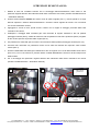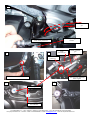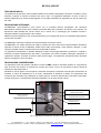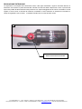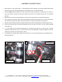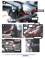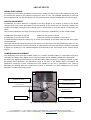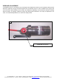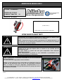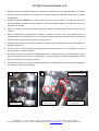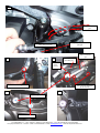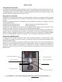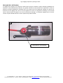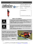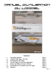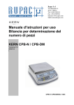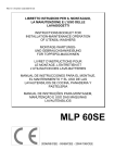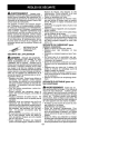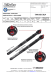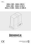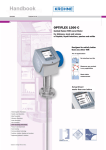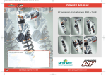
1
AMMORTIZZATORE POSTERIORE HZM 11
CODICE: Y0146HZM11
INDICATO PER:
YAMAHA T-MAX 530
‘12
Aggiornato al : 30.03.2012
NUMERO DI MATRICOLA
DA INDICARE IN CASO DI RECLAMO
PRIMA LA TUA SICUREZZA !
L’ Ammortizzatore è un importante componente della Moto e in questo manuale
è descritto il metodo corretto per il montaggio di esso.
NOTA BENE: l’Ammortizzatore deve essere installato unicamente presso
un’officina specializzata; in caso di dubbi sulle istruzioni qui contenute, Vi
preghiamo di contattare subito un tecnico Bitubo.
Bitubo non potrà essere responsabile di modifiche apportate Prodotto che non
sono contenute in questo manuale, e che non sono autorizzate per iscritto.
Bitubo inoltre non potrà essere responsabile di una non corretta installazione
del Prodotto.
Leggete attentamente questo manuale, per ottenere dall’Ammortizzatore il
massimo delle prestazioni e del rendimento.
NOTA BENE: la garanzia dell’Ammortizzatore cessa nel caso
in cui venga montato in maniera errata, o modificato, senza
l’approvazione scritta da Bitubo.
Bitubo non potrà essere responsabile di danni al prodotto o alle
persone, in caso le istruzioni contenute in questo manuale non
vengano seguite esattamente, o in caso il montaggio
dell’Ammortizzatore non venga effettuato presso una officina
specializzata, e da personale qualificato.
BITUBO RACCOMANDA
Le immagini e le indicazioni riportate sono a titolo indicativo; C.d.a. Bitubo si riserva la facoltà apportare qualsiasi modifica o variazione senza alcun
preavviso.
C.D.A. BITUBO s.n.c. – Via A. Volta,24 – 35037 Z.I. Teolo (PD) ITALY – Tel. (+39) 049-990.34.75 (2 linee ISDN)
Fax (+39) 049-990.34.47 – Cod Fisc. e Part. IVA 02007650282 – E-mail: [email protected] - Internet: http://www.bitubo.com
ISTRUZIONI DI MONTAGGIO
1. Mettere la moto sul cavalletto centrale. Per lo smontaggio dell’ammortizzatore, dello scarico e dei
particolari originali attenersi alle indicazioni della Casa costruttrice del veicolo (Libretto Uso/Manutenzione
– Manuale di Officina).
2. Inserire l’ammortizzatore Bitubo allo stesso modo di quello originale (foto 1), inserire quindi le viti sugli
attacchi superiore e inferiore dell’ammortizzatore e avvitare i bulloni originali del veicolo. Per il momento
non serrare totalmente i bulloni.
3. Appoggiare il veicolo a terra, quindi serrare i bulloni con le coppie di serraggio prescritte dalla Casa
costruttrice del veicolo.
4. Predisporre il fissaggio della vaschetta gas come descritto di seguito: allentare le due viti pedana
passeggero sinistra (foto2), svitare ed estrarre la vite del passacavo tubo freno posteriore (foto2) e togliere
le due viti del coperchio superiore della cinghia (foto 5).
5. Far passare tubo vaschetta gas tra il motore ed il forcellone dietro pedana passeggero sinistra (foto 3-5).
6. Ancorare tubo vaschetta con passavavo fornito nel kit sulla vite indicata del coperchio carter sinistro
motore (foto 4).
7. Fissare la staffa della vaschetta gas sostituendo le due viti originali con le 2 viti M6+rondelle fornite nel kit
(foto 5-6-7). Per la vite inferiore è previsto utilizzo rondella Ø6.5xØ15xs1 fornita nel kit da interporre tra
staffa e telaio.
8. Per il rimontaggio dei particolari originali attenersi alle indicazioni della Casa costruttrice del veicolo
(Libretto Uso/Manutenzione – Manuale di Officina).
1
Attacco inferiore
2
Tubo freno
posteriore
Vite passacavo tubo
freno posteriore
Viti pedana passeggero
sinistra
C.D.A. BITUBO s.n.c. – Via A. Volta,24 – 35037 Z.I. Teolo (PD) ITALY – Tel. (+39) 049-990.34.75 (2 linee ISDN)
Fax (+39) 049-990.34.47 – Cod Fisc. e Part. IVA 02007650282 – E-mail: [email protected] - Internet: http://www.bitubo.com
3
Tubo vaschetta
gas
Pedana passeggero
sinistra
Tubo freno posteriore
Tubo
vaschetta gas
5
4
Staffa vaschetta
gas
Tubo freno
posteriore
Vite carter motore sinistro
Viti coperchio superiore
della cinghia
.
7
6
Viti originali
Vite inferiore
C.D.A. BITUBO s.n.c. – Via A. Volta,24 – 35037 Z.I. Teolo (PD) ITALY – Tel. (+39) 049-990.34.75 (2 linee ISDN)
Fax (+39) 049-990.34.47 – Cod Fisc. e Part. IVA 02007650282 – E-mail: [email protected] - Internet: http://www.bitubo.com
REGOLAZIONI
PRECARICO MOLLA:
La regolazione del precarico molla si effettua atttaverso la rotazione dell’esagono da 32mm; ruotando in senso
antiorario la ghiera si aumenta il precarico da zero a 4mm. La regolazione standard è di 2mm e dona un
assetto leggermente più sostenuto dell’originale. Si consiglia di effettuare la regolazione in step di mezzo giro
per volta.
REGOLAZIONE INTERASSE:
ATTENZIONE: l’ammortizzatore viene fornito con un interasse identico all’originale; una variazione
dell’interasse modifica alcune quote ciclistiche prescritte dalla casa costruttrice del veicolo e può causare una
diminuzione della stabilità del veicolo stesso sia in marcia che in parcheggio (sul cavalletto centrale o
stampella laterale), pregiudicandone la sicurezza.
Effettuare questa regolazione solo ed esclusivamente per un impiego del veicolo in competizioni agonistiche o
circuiti chiusi al traffico.
ATTENZIONE: riducendo l’interasse si aumenta l’altezza da terra del veicolo.
ATTENZIONE: non svitare ulteriormente l’attacco inferiore da come viene fornito l’ammortizzatore andando a
superare la misura di 7mm di filettatura visibile oltre il dado di bloccaggio, come indicato a disegno; in caso
contrario potrebbe essere compromessa la tenuta dell’attacco stesso.
La regolazione dell’interasse si effettua allentando il dado di bloccaggio dell’attacco posteriore e svitando o
avvitando il tassello rispettivamente per ridurlo o aumentarlo così come è indicato nella figura sottostante. A
regolazione ultimata, ricordarsi di serrare il dado di bloccaggio. La regolazione standard prevede l’interasse
identico all’originale ovvero di 318mm.
REGOLAZIONE COMPRESSIONE:
La regolazione posta sul tassello, indicante la scritta “COMP” regola la frenatura idraulica in compressione
oltre ad avere una funzione di controllo del comfort del veicolo, ovvero nei movimenti di basse velocità di
oscillazione della sospensione.
Ruotando la vite di registro verso H (hard) si aumenta la frenatura, ruotandola verso S (soft) si diminuisce la
frenatura. Il campo di regolazione è di 24 clicks. Aumentando la frenatura si ottiene una sospensione dal
movimento più controllato e più adatta ad un utilizzo sportivo, viceversa, diminuendo la frenatura si aumenta il
comfort del veicolo. La taratura base dell’ammortizzatore è di 18 clicks da tutto chiuso.
3
REGOLAZIONE ESTENSIONE
REBOUND ADJUSTER
REGOLAZIONE PRECARICO
PRELOAD ADJUSTER
AUMENTO INTERASSE
INCREASE LENGHT
+
-
REGOLAZIONE COMPRESSIONE
COMPRESSION ADJUSTER
DIMINUZIONE INTERASSE
DECREASE LENGHT
NON OLTRE 7mm
NOT OVER 7mm
REGOLAZIONE INTERASSE
LENGHT ADJUSTER
Fig. 3 - Regolazione compressione, precarico e interasse
C.D.A. BITUBO s.n.c. – Via A. Volta,24 – 35037 Z.I. Teolo (PD) ITALY – Tel. (+39) 049-990.34.75 (2 linee ISDN)
Fax (+39) 049-990.34.47 – Cod Fisc. e Part. IVA 02007650282 – E-mail: [email protected] - Internet: http://www.bitubo.com
REGOLAZIONE ESTENSIONE:
La regolazione a manopola sulla vaschetta di azoto, nella figura sottostante, regola la frenatura idraulica in
estensione ed è efficace in particolare alle alte velocità di movimento della sospensione ovvero in presenza di
improvvise perdite di aderenza della ruota posteriore con rapidi ondeggiamenti del veicolo. Ruotando la vite di
registro in senso orario si aumenta la frenatura, ruotandola in senso antiorario si diminuisce la frenatura. Il
campo di regolazione è di 24 clicks. La taratura standard è di 12 clicks da tutto chiuso.
4
REGOLAZIONE ESTENSIONE
C.D.A. BITUBO s.n.c. – Via A. Volta,24 – 35037 Z.I. Teolo (PD) ITALY – Tel. (+39) 049-990.34.75 (2 linee ISDN)
Fax (+39) 049-990.34.47 – Cod Fisc. e Part. IVA 02007650282 – E-mail: [email protected] - Internet: http://www.bitubo.com
REAR MONOSHOCK HZM11
CODE: Y0146HZM11
INDICATED FOR:
YAMAHA T-MAX 530
‘12
Updated to: 30.03.2013
SERIAL NUMBER
(SEE PAGE 1)
TO BE MENTIONED IN CASE OF CLAIM
FIRST YOUR SAFETY !
The rear shock is an important component of the motorbike and the correct
method of assembling it is described in this manual.
NOTE: The shock absorber must be installed exclusively in a specialized
workshop; in case of doubts regarding the instructions herein, please contact a
Bitubo engineer immediately.
Bitubo cannot be held responsible for any modifications to the Rear Shock not
described in this handbook or not authorised in writing. Moreover Bitubo
cannot be held responsible for the incorrect installation of shock absorber.
Read this handbook carefully so that you can get the best performance and
efficiency out of the Shock absorber.
NOTE: The warranty for the Shock absorber will be invalidated
by incorrect installation or modifications carried out without
Bitubo’s written authorisation.
Bitubo cannot be held responsible for any damages to the
product or injuries to people if the instructions of this handbook
are not followed to the letter or if the Shockabsorber is not fitted
in a specialised workshop or by qualified personnel.
BITUBO RECOMMENDS
Pictures and notes reported are purely as an indications; C.d.a. Bitubo reserves the faculty to make any modification or changes.
C.D.A. BITUBO s.n.c. – Via A. Volta,24 – 35037 Z.I. Teolo (PD) ITALY – Tel. (+39) 049-990.34.75 (2 linee ISDN)
Fax (+39) 049-990.34.47 – Cod Fisc. e Part. IVA 02007650282 – E-mail: [email protected] - Internet: http://www.bitubo.com
ASSEMBLY INSTRUCTIONS
1. Place the bike on the central stand. To disassemble the shock absorber, exhaust and original items follow
the instructions of the vehicle Manufacturer (User/Maintenance - Workshop Manual).
2. Insert the Bitubo shock absorber the same way as the original one (photo 1), followed by the screws on
the top and bottom couplings of the shock absorber and screw on the original vehicle bolts. Do not tighten
the bolts.
3. Rest the bike on the floor and then tighten the bolts to the torques set by the vehicle Manufacturer.
4. Fix the gas bowl as follows: loosen the two passenger left footrest screws (photo 2), unscrew and remove
the rear brake pipe grommet (photo 2) and remove the 2 screws of the belt top cover (photo 5).
5. Route the gas bowl pipe between the engine and the fork behind the passenger left footrest (photos 3-5).
6. Anchor the bowl pipe with the grommet supplied in the kit onto the screw shown on the engine left guard
cover (photo 4).
7. 7. Fix the bracket of the gas bowl replacing the 2 original screws with the 2 x M6 screws + washers
supplied in the kit (photos 5-6-7). For the lower screw use the Ø6.5xØ15xs1 washer supplied in the kit to
be placed in between the bracket and the frame.
8. To assemble the original items follow the instructions of the vehicle Manufacturer (User/Maintenance Workshop Manual).
1
Lower coupling
2
Rear brake pipe
Rear brake pipe
grommet screw
Passenger left
footrest screws
C.D.A. BITUBO s.n.c. – Via A. Volta,24 – 35037 Z.I. Teolo (PD) ITALY – Tel. (+39) 049-990.34.75 (2 linee ISDN)
Fax (+39) 049-990.34.47 – Cod Fisc. e Part. IVA 02007650282 – E-mail: [email protected] - Internet: http://www.bitubo.com
3
Gas bowl pipe
Passenger
left footrest
Tubo freno
Gas bowl
bracket
5
4
Gas bowl
pipe
Rear
brake
pipe
Engine left guard screw
Belt top cover
screws
.
7
6
Original screws
Lower screw
C.D.A. BITUBO s.n.c. – Via A. Volta,24 – 35037 Z.I. Teolo (PD) ITALY – Tel. (+39) 049-990.34.75 (2 linee ISDN)
Fax (+39) 049-990.34.47 – Cod Fisc. e Part. IVA 02007650282 – E-mail: [email protected] - Internet: http://www.bitubo.com
ADJUSTMENTS
SPRING PRELOADING:
The adjustment of the spring preloading is carried out by rotating the 32mm ring nut; by rotating the ring nut in
an anticlockwise direction, the preload increases from zero to 4mm. The standard adjustment is 2mm and
gives a slightly firmer trim than the original one. We recommend you perform the adjustment in half-turn steps.
LENGTH ADJUSTMENT:
ATTENTION: The shock absorber is supplied in the same length as the original; a change in the length
changes some cycle figures prescribed by the manufacturer of the vehicle and can cause the vehicle to be
unstable, both when running and when parked (on the central stand or on th side stand), compromising the
safety.
Carry out this adjustment only when the motorcycle is to be used in competitions o circuits closed to traffic.
ATTENTION: If the length is reduced the vehicle height from the ground increases.
ATTENTION: Do not unscrew the lower attachment from the position it is supplied in order not to exceed 7mm
of visible thread more than the locking ring, as shown in the drawing; on the other hand, the seal of the mount
could be affected.
The length adjustment is done by loosening the locking nut of the back mount and screwing the boss in or out
respectively to decrease or increase it as shown in figure A below. Once the adjustment is finished, remember
to tighten the locking nut. The standard adjustment corresponds to the same length as the original, that is
318mm.
COMPRESSION ADJUSTMENT:
The adjustment of the boss with “COMP” written on it controls hydraulic braking in compression as well as
controlling the comfort of the vehicle, that is in the movements of low oscillation speeds of the suspension.
By rotating the adjusting screw towards H (hard) the braking effect increases, by rotating it towards S (soft),
the braking effect decreases. The adjustment range is 24 clicks. If the braking effect is increased, the
suspension movement is more controlled and more suitable for the use in competitions, vice versa by
decreasing the braking effect the comfort of the vehicle is increased. The basic adjustment of the shock
absorber is 18 clicks from totally closed.
3
REBOUND ADJUSTER
PRELOAD ADJUSTER
COMPRESSION ADJUSTER
INCREASE LENGHT
+
DECREASE LENGHT
NOT OVER 7mm
LENGHT ADJUSTER
Fig. 1 – Rebound compression, preload, lenght.
C.D.A. BITUBO s.n.c. – Via A. Volta,24 – 35037 Z.I. Teolo (PD) ITALY – Tel. (+39) 049-990.34.75 (2 linee ISDN)
Fax (+39) 049-990.34.47 – Cod Fisc. e Part. IVA 02007650282 – E-mail: [email protected] - Internet: http://www.bitubo.com
REBOUND ADJUSTMENT:
The adjusting knob on the nitrogen tray in the figure below adjusts the rebound of the hydraulic braking and is
effective in particular at high movement speeds of the suspension that is in case of sudden loss of grip of the
rear wheel with rapid wobbling of the vehicle. By rotating the adjusting screw towards H (hard) the braking
effect increases, by rotating it towards S (soft), the braking effect decreases. The range of adjustment is 24
clicks. The standard adjustment is 12 clicks from totally closed.
4
REBOUND ADJUSTER
C.D.A. BITUBO s.n.c. – Via A. Volta,24 – 35037 Z.I. Teolo (PD) ITALY – Tel. (+39) 049-990.34.75 (2 linee ISDN)
Fax (+39) 049-990.34.47 – Cod Fisc. e Part. IVA 02007650282 – E-mail: [email protected] - Internet: http://www.bitubo.com
AMORTISSEUR ARRIERE HZM11
CODE: Y0146HZM11
INDIQUE POUR :
YAMAHA T-MAX 530
‘12
Actualisé au : 30.03.2012
N. DE SERIE
(VOIR PAGE 1)
A INDIQUER EN CAS DE RECLAMATION
VOTRE SECURITE AVANT TOUT !
L’amortisseur est un élément important de la moto et dans ce manuel, nous
décrivons la bonne méthode à utiliser pour son montage.
N.B.: L’amortisseur doit être installé uniquement par un garage spécialisé ; en
cas de doutes sur les instructions contenues ici, nous vous prions de contacter
tout de suite un technicien Bitubo.
Bitubo ne pourra être tenu pour responsable des modifications apportées au
produit qui ne sont pas reprises dans ce manuel et qui n’auront pas été
autorisées par écrit.
En outre, Bitubo ne pourra être tenu pour responsable d’une mauvaise
installation du produit.
Lisez attentivement ce manuel et vous obtiendrez la performance et le
rendement maximum de l’amortisseur.
N.B.: La garantie de l’amortisseur est annulée au cas où il est monté de
manière erronée ou
s’il est modifié sans l’approbation écrite de Bitubo.
Bitubo ne pourra être tenu pour responsable des dommages causés au
produit ou aux personnes, dans le cas où les instructions contenues
dans ce manuel ne sont pas respectées scrupuleusement ou si le
montage de l’amortisseur n’est pas effectué dans un garage spécialisé et
par un personnel qualifié.
Les images et les indications sont à titre indicatif ; C.d.a. Bitubo se réserve toutes les droites d’effectuer toutes les modifications ou changements sans
préavis
C.D.A. BITUBO s.n.c. – Via A. Volta,24 – 35037 Z.I. Teolo (PD) ITALY – Tel. (+39) 049-990.34.75 (2 linee ISDN)
Fax (+39) 049-990.34.47 – Cod Fisc. e Part. IVA 02007650282 – E-mail: [email protected] - Internet: http://www.bitubo.com
INSTRUCTIONS DE MONTAGE
1. Mettez la moto sur la béquille centrale. Pour démonter l’amortisseur, le tuyau d’échappement et les pièces
d’origine, suivez les indications du constructeur du véhicule (Manuel d’utilisation et d’entretien – Manuel
de réparation).
2. Montez l’amortisseur Bitubo de la même façon que celui d’origine (photo 1), placez les vis sur les
embouts supérieur et inférieur de l’amortisseur et vissez les boulons d’origine du véhicule, sans les serrer
à fond pour le moment.
3. Posez le véhicule au sol et serrez les boulons aux couples de serrage indiqués par le constructeur du
véhicule.
4. Fixez la cartouche gaz comme décrit ci-dessous : desserrez les deux vis du repose-pied gauche du
passager (photo 2), dévissez et enlevez la vis du passe-câble du tube de frein arrière (photo 2) et enlevez
les deux vis du couvercle supérieur de la courroie (photo 5).
5. Faîtes passer le tuyau de la cartouche gaz entre le moteur et la fourche derrière le repose-pied gauche du
passager (photos 3-5).
6. Fixez le tuyau de la cartouche gaz avec le passe-câble fourni dans le kit sur la vis indiquée du couvercle
du carter gauche du moteur (photo 4).
7. Fixez l’étrier de la cartouche gaz en remplaçant les deux vis originales par les 2 vis M6+rondelles fournies
dans le kit (photos 5-6-7). Pour la vis inférieure, il est prévu d’utiliser la rondelle Ø6.5xØ15xs1 fournie
dans le kit, à placer entre l’étrier et le cadre.
8. Pour remonter les pièces d’origine, suivez les indications du constructeur du véhicule (Manuel d’utilisation
et d’entretien – Manuel de réparation).
1
Embout inférieur
2
Tube de frein arrière
Vis passe-câble
tube de frein
Vis repose-pied gauche
du passager
C.D.A. BITUBO s.n.c. – Via A. Volta,24 – 35037 Z.I. Teolo (PD) ITALY – Tel. (+39) 049-990.34.75 (2 linee ISDN)
Fax (+39) 049-990.34.47 – Cod Fisc. e Part. IVA 02007650282 – E-mail: [email protected] - Internet: http://www.bitubo.com
3
Tuyau cartouche
gaz
Repose-pied gauche du
passager
Tube de frein arrière
Étrier cartouche
gaz
5
4
Tuyau
cartouche gaz
Tube de
frein
arrière
Vis carter moteur gauche
Vis couvercle supérieur
de la courroie
.
7
6
Vis originales
Vis inférieure
C.D.A. BITUBO s.n.c. – Via A. Volta,24 – 35037 Z.I. Teolo (PD) ITALY – Tel. (+39) 049-990.34.75 (2 linee ISDN)
Fax (+39) 049-990.34.47 – Cod Fisc. e Part. IVA 02007650282 – E-mail: [email protected] - Internet: http://www.bitubo.com
REGLAGES
PRECHARGE DU RESSORT:
Le réglage de la précharge du ressort s’effectue au moyen de la rotation de la vis à six pans de 32 mm ; en
tournant dans le sens contraire des aiguilles d’une montre, la bague augmente la précharge de zéro à 4 mm.
Le réglage standard est de 2 mm et donne une assiette légèrement plus soutenue que celle de l’original. Il est
conseillé d’effectuer le réglage par un demi tour à la fois.
REGLAGE DE L’ENTRAXE:
ATTENTION : l’amortisseur est fourni avec un entraxe identique à l’original ; une variation de l’entraxe modifie
certaines hauteurs prescrites par le constructeur du véhicule et peut causer une diminution de la stabilité du
véhicule.
Effectuer ce réglage uniquement et exclusivement pour une utilisation du véhicule en compétition ou sur des
circuits interdits au trafic.
ATTENTION : En augmentant l’entraxe de l’amortisseur, la hauteur du véhicule par rapport au sol diminue, en
réduisant l’entraxe, la hauteur du véhicule par rapport au sol augmente.
ATTENTION : ne pas dépasser la mesure de 6 mm de filetage visible au-delà de l’écrou de blocage, comme
indiqué sur le dessin ; dans le cas contraire, le joint de la fixation pourrait s'abîmer.
Le réglage de l’entraxe s’effectue en desserrant l’écrou de blocage de la fixation arrière et en dévissant ou en
vissant le support, respectivement pour le réduire ou l’augmenter, comme cela est indiqué dans la figure cidessous. Dès que le réglage est terminé, ne pas oublier de serrer l'écrou de blocage. Le réglage standard
prévoit un entraxe identique à l’original c'est-à-dire de 315 mm et peut être modifié de plus ou moins 3 mm.
REGLAGE COMPRESSION:
Le réglage situé sur le support, indiquant “COMP”, règle le freinage hydraulique en compression et a aussi
une fonction de contrôle du confort du véhicule, c’est-à-dire au niveau des mouvements d’oscillation de la
suspension à faible vitesse.
En tournant la vis de réglage vers H (hard) on augmente le freinage, en la tournant vers S (soft) on diminue le
freinage. Le champ de réglage est de 24 clicks. En augmentant le freinage, on obtient une suspension du
mouvement mieux contrôlée et plus adaptée à un usage sportif, vice-versa, en diminuant le freinage, on
augmente le confort du véhicule. La mise au point de base de l’amortisseur est de 18 clicks à partir de la
position fermée.
3
REGLAGE DE L’EXTENSION
REGLAGE PRECHARGE
REGLAGE COMPRESSION
AUGMENTATION ENTRAXE
+
REDURE ENTRAXE
AUCUN AUTRE 7mm
REGLAGE DE L’ENTRAXE
C.D.A. BITUBO s.n.c. – Via A. Volta,24 – 35037 Z.I. Teolo (PD) ITALY – Tel. (+39) 049-990.34.75 (2 linee ISDN)
Fax (+39) 049-990.34.47 – Cod Fisc. e Part. IVA 02007650282 – E-mail: [email protected] - Internet: http://www.bitubo.com
Fig.3 - Réglage compression, precharge, entraxe
REGLAGE DE L’EXTENSION
Le réglage avec poignée sur le réservoir d’azote, dans la figure ci-dessous, règle le freinage hydraulique en
extension et est particulièrement efficace aux grandes vitesses de mouvement de la suspension ou bien en
présence de pertes d’adhérence soudaines de la roue arrière avec des flottements rapides du véhicule. En
tournant la vis de réglage vers dans le sens des aiguilles d'une montre on augmente le freinage, en la tournant
vers en sense inverse des aiguilles d'une montre on diminue le freinage. Le champ de réglage est de 24 clicks.
La mise au point standard est de 12 clicks à partir de la position fermée.
4
REGLAGE DE L’EXTENSION
C.D.A. BITUBO s.n.c. – Via A. Volta,24 – 35037 Z.I. Teolo (PD) ITALY – Tel. (+39) 049-990.34.75 (2 linee ISDN)
Fax (+39) 049-990.34.47 – Cod Fisc. e Part. IVA 02007650282 – E-mail: [email protected] - Internet: http://www.bitubo.com