1
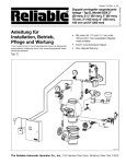
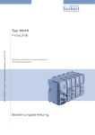
Type 0470, 5470
3/2 or 4/2 way solenoid valve
3/2- bzw. 4/2-Wege-Magnetventil
Électrovanne 3/2 ou 4/2 voies
Operating Instructions
Bedienungsanleitung
Manuel d‘utilisation
Bürkert Fluid Control Systems
Sales Center
Christian-Bürkert-Str. 13-17
D-74653 Ingelfingen
Tel. + 49 (0) 7940 - 10 91 111
Fax + 49 (0) 7940 - 10 91 448
E-mail: [email protected]
International address
www.burkert.com
Manuals and data sheets on the Internet: www.burkert.com
Bedienungsanleitungen und Datenblätter im Internet: www.buerkert.de
Manuels et fiches techniques sur Internet : www.buerkert.fr
© Bürkert Werke GmbH, 2015
Operating Instructions 1502/14_EU-ML_00803445 / Original DE
www.burkert.com
EN
Type 0470, 5470
1
THE OPERATING INSTRUCTIONS
The operating instructions contain important information.
▶▶ Read the operating instructions carefully and follow the safety
instructions in particular.
▶▶ The operating instructions must be available to every user.
▶▶ The liability and warranty for Type 0470, 5470 are not applicable if
the operating instructions are not followed.
1.1 Symbols
▶▶ Designates instructions for risk prevention.
→→Designates a procedure which you must carry out.
Warning of serious or fatal injuries:
DANGER!
In case of imminent danger.
Warning of minor or
moderately severe injuries:
CAUTION!
WARNING!
In case of potential danger.
Warning of damage:
NOTE!
1.2 Definition of the term “device”
The term “device” used in the instructions always refers to the
Type 0470, 5470.
INTENDED USE
Incorrect use of the solenoid valve Type 0470, 5470 may be a
hazard to people, nearby equipment and the surrounding area.
▶▶ The device is used exclusively as 3/2 or 4/2-way solenoid valve for
the media permitted according to the data sheet of the corresponding type.
▶▶ Provided the cable plug is connected and installed correctly,
e.g. Bürkert Type 2506 (for Type 5470) or Type 1054 (for Type
0470), the device satisfies degree of protection IP65 in accordance
with DIN EN 60529 / IEC 60529.
▶▶ In a hazardous area, the device may be used only in accordance
with the specification on the separate Ex type label. For the use,
observe the additional information enclosed with the device with
safety instructions for the EX area.
▶▶ Devices without a separate Ex type label may not be used in a
potentially explosive area.
▶▶ Use according to the authorized data, operating conditions and conditions of use specified in the contract documents, the data sheet
and the operating instructions.
▶▶ Correct transport, correct storage and installation as well as careful
use and maintenance are essential for reliable and problem-free
operation.
▶▶ Use the device only for its intended purpose.
english
2
3
2
BASIC SAFETY INSTRUCTIONS
These safety instructions do not make allowance for any contingencies and events which may arise during assembly, operation and
maintenance.
Danger – high pressure!
▶▶ Turn off the pressure and vent the lines before loosening lines or
valves.
Risk of electric shock!
▶▶ Before reaching into the device or the equipment, switch off the
power supply and secure to prevent reactivation!
▶▶ Observe applicable accident prevention and safety regulations for
electrical equipment!
Risk of injury from greatly accelerated device parts!
▶▶ Before pressurizing the valve, check that all screw connections
and screw joints are tight and secure.
Risk of burns/danger of fire during long-term operation due to
hot device surface!
▶▶ Keep the device away from highly flammable substances and media
and do not touch with bare hands.
To prevent injuries/damage:
▶▶ Do not make any internal or external changes to the device and
safeguard against unintentional actuation.
▶▶ Installation and maintenance work may be carried out only by authorized technicians with the appropriate tools.
▶▶ After an interruption in the electrical or pneumatic supply, ensure
that the process is restarted in a defined or controlled manner.
▶▶ Do not subject the housing to mechanical loads.
▶▶ Observe the general accepted technical rules.
3.1 Restrictions
If exporting the device, observe any existing restrictions.
english
4
5
APPROVALS
3
STRUCTURE AND FUNCTION
The approval mark indicated on the Bürkert labels refers to the Bürkert
products.
The valves can be mounted in blocks on the modular pneumatic base
rail Type MP05.
Devices which must bear the type approval mark were approved at the
Kraftfahrtbundesamt under the type approval number
5.1 Structure of the standard designs
e1*72/245*2006/96*5791*00
5.1.1Connections
and are put into circulation with the indicated type approval mark.
All connections are identified by numbers on the valve surface. These
refer to the following functions:
e1
035791
You can obtain an extract of the type approval from the address below.
Bürkert Werke GmbH
CQ-Approval Management
Christian-Bürkert-Str.13-17
D-74653 Ingelfingen
4
english
Number
1
2 und 4
3
Function
Pressure inlet port
Working port
Exhaust port
Type 0470, 5470
5.2 Circuit functions
5.1.2Valve structure Type 5470
Cable plug
Type 2506
Pilot valve
Type 6106
C
3/2-way valve
Normally inlet port 1 closed, working port 2
connected with exhaust port 3.
D
3/2-way valve
Normally inlet port 1 connected with working
port 2, exhaust port 3 closed.
Manual control
Exhaust port 3
Pressure inlet port 1
G
Working port 4
B
Working port 2
P R
5.1.3Valve structure Type 0470
4/2-way valve
Normally inlet port 1 connected with working
port 2, working port 4 connected with exhaust
port 3.
Cable plug
Type 1054
Solenoid coil
Type AC27
Exhaust port 3
Pressure inlet port 1
Working port 4
Working port 2
english
6
TECHNICAL DATA
6.4 Operating conditions
Please observe the specifications on the data sheet and on
the type label.
6.1 Conformity
The solenoid valve Type 0470, 5470 is compliant with EC directives
as stated in the EC Declaration of Conformity.
6.2 Standards
The applied standards which are used to demonstrate compliance with
the EC Directives are listed in the EC Prototype Examination Certificate
and/or the EC Declaration of Conformity.
6.3 Type label
Circuit function
Example:
Made in Germany
Type
Order number
Fig. 1:
5470
G1/8
24V
G 4,0
PN2–10bar
DC
2W
00203236W1YMG
5
Orifice
Connection type,
permitted pressure range
Voltage (± 10 %),
frequency,
output
Manufacturer code
Example of type label on the pilot-controlled solenoid valve
Type 5470
Ambient
temperature
Permitted
medium temp.
Compr. air quality
Permitted media
Permitted
pressure range
Degree of
protection
Operating
duration
–10 °C ... +55 °C (please observe temperature
restrictions on account of approvals)
–10 °C ... +50 °C
ISO 8573-1:2010, Class 7.4.41)
Filtered compressed air oiled and unoiled, neutral
gases
Observe specifications on type label
Pressure difference at least 2 bar between
ports 1 and 3
IP65 as per DIN EN 60529 / IEC 60529 with
correctly connected and fitted cable plug,
e.g. Bürkert Type 2506
Unless otherwise indicated on the type label, the
solenoid system is suitable for continuous operation
To prevent the expanded compressed air from freezing, its pressure dew
point must be at least 10 K lower than the medium temperature.
1)
english
6
Important information for functional reliability during continuous
operation!
If the equipment is switched off for a long period, it is recommended to activate the valves at least 1-2 per day.
Service life:
High switching frequency and high pressures reduce the service life.
The valves operate maintenance-free.
6.5 Materials
Housing material: PA
Seal material:
NBR
7 ASSEMBLY
7.1 Safety instructions
DANGER!
Risk of injury from high pressure in the system!
▶▶ Turn off the pressure and vent the lines before loosening lines or
valves.
Risk of injury due to electrical shock!
▶▶ Before reaching into the device or the equipment, switch off the
power supply and secure to prevent reactivation!
▶▶ Observe applicable accident prevention and safety regulations for
electrical equipment!
WARNING!
Risk of injury from greatly accelerated device parts and unconnected whiplashing compressed air hoses!
▶▶ Before pressurizing the valve, check that all screw connections and
screw joints are tight and secure.
Risk of injury from improper assembly!
▶▶ Assembly may only be carried out by authorized technicians and
with the appropriate tools!
english
7
Type 0470, 5470
Risk of injury from unintentional activation of the system and
uncontrolled restart!
▶▶ Secure system against unintentional activation.
▶▶ Following assembly, ensure a controlled restart.
Tightening torque 1st Level 0.1 Nm (± 0.05 Nm),
2nd Level 0.2 Nm (± 0.05 Nm).
7.2 Type 5470, turning the solenoid coil
The valves are supplied fully assembled. If the solenoid coil in the
pilot valve is in an unfavorable position for installation, the coil can be
turned 180°.
180°
WARNING!
Risk of electrical shock if the coil is incorrectly fitted!
▶▶ During installation, make sure that the coil is firmly seated on the
valve body so that the protective conductor connection of the coil is
in contact with the valve housing.
▶▶ Check the function of the protective conductor (for test values, see
“Tab. 1”, page 11).
Fig. 2:
Typ 5470: The solenoid coil in the pilot valve can be turned by 180°
→→Loosen M2 screws and pull coil away from the valve body.
→→Turn coil, attach to valve body, and screw on with M2 screws,
tightening alternately step by step. While doing so, observe the
tightening torque:
english
8
7.3 Conversion from a 4/2 to a 3/2 way
valve
To convert the 4/2-way valve
into a 3/2-way valve, you must
seal connection 2 or connection
4 with a plug depending on the
required operating principle.
Connection 2
Connection 4
Circuit function
sealed
open
C
open
sealed
D
7.4 Pneumatic connection
WARNING!
Risk of injury from greatly accelerated device parts and unconnected whiplashing compressed air hoses!
▶▶ Before pressurizing the valve, check that all screw connections and
screw joints are tight and secure.
Installation position: any, preferably with solenoid system face up.
Before connecting:
→→Check whether hose lines are dirty and clean.
→→If required, install a dirt filter upstream of the valve inlet (≤ 5 µm).
Pneumatic connection:
NOTE!
Risk of breakage!
▶▶ Do not use coil as a lever arm.
▶▶ Do not use a cylinder wrench to tighten screws.
→→Hold the device by hand on the housing and connect to the hose
line. Do not exceed the standard screw-in depth.
→→Seal with PTFE tape or elastomer seal.
english
→→Observe allocation of the connections
(see Chapter “5.1.1 Connections”, page 4).
→→Align hose lines.
9
7.5.1Connection of cable plug to the power
supply
Example Type 5470
7.5 Electrical connection
Seal
Approved cable plug
(e.g. Type 2506 or other in accordance with DIN ISO 175301-803
shape C)
WARNING
Risk of injury due to electrical shock!
▶▶ Before reaching into the system, switch off the electrical power
supply and secure to prevent reactivation!
▶▶ Observe applicable accident prevention and safety regulations for
electrical equipment!
▶▶ When screwing the coil onto the device socket, make sure the
seal is correctly seated.
If the protective conductor contact between the coil and housing is
missing, there is a danger of electric shock!
▶▶ Always connect protective conductor.
▶▶ Check electrical continuity between coil and housing.
Observe max.
tightening
torque!
Fig. 3:
Connection of cable plug to the power supply, Example type 5470
→→Tighten cable plug (for authorized types see data sheet), observing
maximum torque (0.3 Nm).
→→Check that seal is fitted correctly.
→→Connect protective conductor and
check electrical continuity
between coil and housing (s. “Tab. 1”).
10
english
Type 0470, 5470
7.6 Actuating the pulse version
NOTE!
If the cable plug is designed in such a way that the screw is pointing
upwards, insert a seal made of a material compatible with your
process under the screw head.
The correct polarity is a prerequisite for the device to function:
Observe the markings on the coil surface. Pulse duration at
least 50 ms.
pin 1
pin 2
pin 1
pin 2
Note the voltage and current type as specified on the type
label.
Pesistor
Test voltage
Test current
max. 0.1 Ω
12 V
1A
Tab. 1:
Test values protective conductor function
Plug configuration
Effect
(+) on pin 2
(–) on pin 1
Pilot valve opened
(+) on pin 1
(–) on pin 2
Pilot valve closed
1–3
2–3
1–4
1–2
4–3
4–3
CFG
CFC
CFG
CFC
english
8
MANUAL CONTROL
11
10 MAINTENANCE, TROUBLESHOOTING
If the valve is used according to these operating instructions, the valve
will operate maintenance-free.
10.1Safety instructions
WARNING!
0 = rest position
1 = switching
position
Fig. 4:
9
Manual control based on the example of Type 5470
DISASSEMBLY
Disassembly is in reverse sequence to assembly.
12
Risk of injury from improper maintenance!
▶▶ Maintenance may only be carried out by authorized technicians
and with the appropriate tools!
Risk of injury due to electrical shock!
▶▶ Before reaching into the device or the equipment, switch off the
power supply and secure to prevent reactivation!
Danger – high pressure!
▶▶ Turn off the pressure and vent the lines before loosening lines or
valves.
Risk of injury from unintentional activation of the system and
uncontrolled restart!
▶▶ Secure system against unintentional activation.
▶▶ Following maintenance, ensure a controlled restart.
english
10.2Malfunctions
If malfunctions occur, check whether:
•the device has been installed according to the instructions,
•the electrical and pneumatic connections are correct,
•the device is not damaged,
•all screws have been tightened,
•the voltage and pressure have been switched on,
•the pipelines are clean,
•the manual control is in the normal position.
Valve does not switch
Possible causes:
•short circuit or coil interrupted,
•core or core area dirty,
•medium pressure outside the permitted pressure range.
Valve does not close
Possible causes:
•inner compartment of the valve is dirty.
11 TRANSPORTATION, STORAGE,
DISPOSAL
NOTE!
Transport damage!
Inadequately protected devices may be damaged during
transportation.
▶▶ Protect the device against moisture and dirt in shock-resistant
packaging during transportation.
▶▶ Prevent the temperature from exceeding or dropping below the
permitted storage temperature.
▶▶ Protect the electrical interfaces of the coil and the pneumatic
connections from damage by placing protective caps on them.
Incorrect storage may damage the device.
▶▶ Store the device in a dry and dust-free location!
▶▶ Storage temperature –40 °C ... +80 °C.
Damage to the environment caused by device components
contaminated with media.
▶▶ Dispose of the device and packaging in an environmentally friendly
manner!
▶▶ Observe applicable disposal and environmental regulations.
english
13
Type 0470, 5470
3/2 or 4/2 way solenoid valve
3/2- bzw. 4/2-Wege-Magnetventil
Électrovanne 3/2 ou 4/2 voies
Operating Instructions
Bedienungsanleitung
Manuel d‘utilisation
Bürkert Fluid Control Systems
Sales Center
Christian-Bürkert-Str. 13-17
D-74653 Ingelfingen
Tel. + 49 (0) 7940 - 10 91 111
Fax + 49 (0) 7940 - 10 91 448
E-mail: [email protected]
International address
www.burkert.com
Manuals and data sheets on the Internet: www.burkert.com
Bedienungsanleitungen und Datenblätter im Internet: www.buerkert.de
Manuels et fiches techniques sur Internet : www.buerkert.fr
© Bürkert Werke GmbH, 2015
Operating Instructions 1502/14_EU-ML_00803445 / Original DE
www.burkert.com
DE
Typ 0470, 5470
1
DIE BEDIENUNGSANLEITUNG
Die Bedienungsanleitung enthält wichtige Informationen.
▶▶ Die Bedienungsanleitung sorgfältig lesen und die Hinweise zur
Sicherheit beachten.
▶▶ Die Bedienungsanleitung muss jedem Benutzer zur Verfügung stehen.
▶▶ Die Haftung und Gewährleistung für Typ 0470, 5470 entfällt, wenn
die Anweisungen der Bedienungsanleitung nicht beachtet werden.
1.1 Darstellungsmittel
▶▶ markiert eine Anweisung zur Gefahrenvermeidung.
→→markiert einen Arbeitsschritt, den Sie ausführen müssen.
Warnung vor schweren oder tödlichen Verletzungen:
GEFAHR!
WARNUNG!
Bei unmittelbarer Gefahr.
Warnung vor leichten oder
mittelschweren Verletzungen:
VORSICHT!
Bei möglicher Gefahr.
Warnung vor Sachschäden:
HINWEIS!
1.2 Begriffsdefinition „Gerät“
Der in der Anleitung verwendete Begriff „Gerät“ bezeichnet immer den
Typ 0470, 5470.
BESTIMMUNGSGEMÄSSER GEBRAUCH
Bei nicht bestimmungsgemäßem Einsatz des Magnetventils
Typ 0470, 5470 können Gefahren für Personen, Anlagen in der
Umgebung und die Umwelt entstehen.
▶▶ Das Gerät dient ausschließlich als 3/2- bzw. 4/2-Wege-Magnetventil für die laut Datenblatt des entsprechenden Typs zulässigen Medien.
▶▶ Mit einer sachgemäß angeschlossenen und montierten Gerätesteckdose, z. B. Bürkert Typ 2506 (bei Magnetventil Typ 5470) oder Typ
1054 (bei Magnetventil Typ 0470) erfüllt das Gerät die Schutzart IP65
nach DIN EN 60529 / IEC 60529.
▶▶ Im explosionsgefährdeten Bereich darf das Gerät nur entsprechend
der Spezifikation auf dem separaten Ex-Typschild eingesetzt werden.
Für den Einsatz muss die dem Gerät beiliegende Zusatzinformation mit
Sicherheitshinweisen für den Ex-Bereich beachtet werden.
▶▶ Geräte ohne separates Ex-Typschild dürfen nicht im explosionsgefährdeten Bereich eingesetzt werden.
▶▶ Für den Einsatz die in den Vertragsdokumenten, dem Datenblatt und
der Bedienungsanleitung spezifizierten zulässigen Daten, Betriebs- und
Einsatzbedingungen beachten.
▶▶ Voraussetzungen für den sicheren und einwandfreien Betrieb sind
sachgemäßer Transport, sachgemäße Lagerung und Installation sowie
sorgfältige Bedienung und Instandhaltung.
▶▶ Das Gerät nur bestimmungsgemäß einsetzen.
deutsch
14
3
2
GRUNDLEGENDE
SICHERHEITSHINWEISE
Diese Sicherheitshinweise berücksichtigen keine Zufälligkeiten und
Ereignisse, die bei Montage, Betrieb und Wartung auftreten können.
Verletzungsgefahr durch hohen Druck!
▶▶ Vor dem Lösen von Leitungen oder Ventilen den Druck abschalten
und Leitungen entlasten.
Verletzungsgefahr durch elektrische Spannung!
▶▶ Vor Eingriffen in das Gerät oder die Anlage Spannung abschalten
und vor Wiedereinschalten sichern!
▶▶ Die geltenden Unfallverhütungs- und Sicherheitsbestimmungen für
elektrische Geräte beachten!
Verletzungsgefahr durch stark beschleunigte Geräteteile!
▶▶ Vor Beaufschlagen des Ventils mit Druck alle Schlauchverbindungen und Verschraubungen auf festen, sicheren Sitz überprüfen.
Verbrennungsgefahr/Brandgefahr bei Dauerbetrieb durch heiße
Geräteoberfläche!
▶▶ Das Gerät von leicht brennbaren Stoffen und Medien fernhalten und
nicht mit bloßen Händen berühren.
Zum Schutz vor Verletzungen/Sachschäden beachten:
▶▶ Am Gerät keine inneren oder äußeren Veränderungen vornehmen
und vor unbeabsichtigter Betätigung sichern.
▶▶ Installations- und Instandhaltungsarbeiten dürfen nur von autorisiertem Fachpersonal mit geeignetem Werkzeug ausgeführt werden.
▶▶ Nach einer Unterbrechung der elektrischen oder pneumatischen
Versorgung ist ein definierter oder kontrollierter Wiederanlauf des
Prozesses zu gewährleisten.
▶▶ Gehäuse nicht mechanisch belasten.
▶▶ Die allgemeinen Regeln der Technik einhalten.
3.1 Beschränkungen
Beachten Sie bei der Ausfuhr des Geräts gegebenenfalls bestehende
Beschränkungen.
deutsch
4
5
ZULASSUNGEN
15
AUFBAU UND FUNKTION
Die auf den Bürkert Typschildern aufgebrachte Zulassungskennzeichnung bezieht sich auf die Bürkert Produkte.
Die Ventile können auf der modularen pneumatischen Grundschiene
Typ MP05 zu Ventilblöcken montiert werden.
Geräte, die das Typgenehmigungszeichen tragen müssen, wurden
beim Kraftfahrtbundesamt unter der Typgenehmigungsnummer
5.1 Aufbau der Standard-Ausführungen
e1*72/245*2006/96*5791*00
genehmigt und werden mit dem gezeigten Typgenehmigungzeichen in
den Verkehr gebracht.
e1
035791
Einen Auszug der Typgenehmigung erhalten Sie unter folgender
Adresse:
Bürkert Werke GmbH
CQ-Approval Management
Christian-Bürkert-Str.13-17
D-74653 Ingelfingen
16
deutsch
5.1.1Anschlüsse
Alle Anschlüsse sind auf der Ventiloberfläche mit Nummern gekennzeichnet. Diese verweisen auf folgende Funktionen:
Nummer
1
2 und 4
3
Funktion
Druckanschluss
Arbeitsanschluss
Entlüftungsanschluss
Typ 0470, 5470
5.2 Wirkungsweisen
5.1.2Aufbau Magnetventil Typ 5470
Gerätesteckdose
Typ 2506
Vorsteuerventil
Typ 6106
3/2-Wege-Ventil
In Ruhestellung Druckanschluss 1
geschlossen, Arbeitsanschluss 2 nach
Anschluss 3 offen.
3/2-Wege-Ventil
In Ruhestellung Druckanschluss 1 nach
Arbeitsanschluss 2 geöffnet, Anschluss 3
geschlossen.
4/2-Wege-Ventil
in Ruhestellung Druckanschluss 1 nach
Arbeitsanschluss 2 geöffnet, Arbeitsanschluss
4 nach Ausgang 3 geöffnet.
C
Handbetätigung
D
Entlüftungsanschluss 3
Druckanschluss 1
Arbeitsanschluss 4
Arbeitsanschluss 2
G
B
5.1.3Aufbau Magnetventil Typ 0470
P R
Gerätesteckdose
Typ 1054
Magnetspule
Typ AC27
Entlüftungsanschluss 3
Druckanschluss 1
Arbeitsanschluss 4
Arbeitsanschluss 2
deutsch
6
TECHNISCHE DATEN
6.4 Betriebsbedingungen
Bitte die Angaben auf dem Datenblatt und dem Typschild
beachten.
6.1 Konformität
Das Magnetventil Typ 0470, 5470 ist konform zu den EG-Richtlinien
entsprechend der EG-Konformitätserklärung.
6.2 Normen
Die angewandten Normen, mit denen die Konformität mit den EG-Richtlinien nachgewiesen wird, sind in der EG-Baumusterprüfbescheinigung
und/oder der EG-Konformitätserklärung nachzulesen.
6.3 Typschild
Wirkungsweise
Typ
Made in Germany
Beispiel:
Bestellnummer
Bild 1:
5470
G1/8
24V
G 4,0
PN2–10bar
DC
2W
00203236W1YMG
17
Nennweite
Anschlussart,
zulässiger Druckbereich
Spannung (± 10 %),
Stromart/Frequenz,
Leistung
Umgebungstemperatur
Zulässige
Mediumstemp.
Druckluftqualität
Zulässige
Medien
Zulässiger
Druckbereich
Schutzart
Betriebsdauer
Hersteller-Code
Beispiel eines Typschilds des vorgesteuerten Magnetventils
Typ 5470
–10 °C ... +55 °C (bitte Temperatureinschränkungen aufgrund von Zulassungen beachten)
–10 °C ... +50 °C
ISO 8573-1:2010, Klasse 7.4.41)
Gefilterte Druckluft geölt und ungeölt,
neutrale Gase
Angaben auf Typschild beachten
Druckdifferenz mindestens 2 bar zwischen
Anschlüssen 1 und 3
IP65 nach DIN EN 60529 / IEC 60529
mit sachgemäß angeschlossener und montierter
Gerätesteckdose, z. B. Bürkert Typ 2506
Wenn auf dem Typschild nicht anders angegeben,
ist das Magnetsystem für Dauerbetrieb geeignet
Um ein Vereisen der expandierten Druckluft zu vermeiden, muss deren
Drucktaupunkt mindestens 10 K niedriger als die Mediumstemperatur sein.
1)
deutsch
18
Wichtiger Hinweis für die Funktionssicherheit bei Dauerbetrieb!
Bei langem Stillstand wird eine Mindestbetätigung von 1-2
Schaltungen pro Tag empfohlen.
Lebensdauer:
Hohe Schaltfrequenz und hohe Drücke verringern die Lebensdauer.
Die Ventile arbeiten wartungsfrei.
6.5 Werkstoffe
Gehäusewerkstoff:
PA
Dichtwerkstoff:
NBR
7
MONTAGE
7.1 Sicherheitshinweise
GEFAHR!
Verletzungsgefahr durch hohen Druck in der Anlage!
▶▶ Vor dem Lösen von Leitungen oder Ventilen den Druck abschalten
und Leitungen entlasten.
Verletzungsgefahr durch Stromschlag!
▶▶ Vor Eingriffen in das Gerät oder die Anlage Spannung abschalten
und vor Wiedereinschalten sichern!
▶▶ Die geltenden Unfallverhütungs- und Sicherheitsbestimmungen für
elektrische Geräte beachten!
WARNUNG!
Verletzungsgefahr durch stark beschleunigte Geräteteile und
nicht verbundene herumschlagende Druckluftschläuche!
▶▶ Vor Beaufschlagen des Ventils mit Druck alle Schlauchverbindungen und Verschraubungen auf festen, sicheren Sitz überprüfen.
Verletzungsgefahr bei unsachgemäßer Montage!
▶▶ Die Montage darf nur autorisiertes Fachpersonal mit geeignetem
Werkzeug durchführen!
deutsch
19
Typ 0470, 5470
Verletzungsgefahr durch ungewolltes Einschalten der Anlage
und unkontrollierten Wiederanlauf!
▶▶ Anlage vor unbeabsichtigtem Betätigen sichern.
▶▶ Nach der Montage einen kontrollierten Wiederanlauf gewährleisten.
Anziehdrehmoment 1
. Stufe 0,1 Nm (± 0,05 Nm),
2. Stufe 0,2 Nm (± 0,05 Nm).
7.2 Typ 5470, Drehen der Magnetspule
Die Ventile werden fertig montiert geliefert. Sollte die Lage der Magnetspule des Vorsteuerventils für die Montage ungünstig sein, kann die
Spule um 180° gedreht werden.
180°
WARNUNG!
Gefahr durch Stromschlag bei falscher Montage der Spule!
▶▶ Bei der Montage beachten, dass die Spule fest auf dem Ventilkörper aufsitzt, damit der Schutzleiteranschluss der Spule Verbindung
zum Ventilgehäuse hat.
▶▶ Schutzleiterfunktion prüfen (Prüfwerte siehe „Tab. 1“ auf Seite 23).
Bild 2:
Typ 5470: Magnetspule des Vorsteuerventils kann um 180° gedreht
werden
→→Schrauben M2 lösen und Spule vom Ventilkörper abziehen.
→→Spule drehen, auf Ventilkörper aufsetzen und mit Schrauben M2
abwechselnd stufenweise verschrauben. Dabei Anziehdrehmoment beachten:
deutsch
20
7.3 Umbau von 4/2- in 3/2-Wege-Ventil
Zum Umbau des 4/2-WegeVentils in ein 3/2-Wege-Ventil
muss je nach gewünschter Wirkungsweise Anschluss 2 oder
Anschluss 4 mit einem Stopfen
verschlossen werden.
7.4 Pneumatischer Anschluss
WARNUNG!
Verletzungsgefahr durch stark beschleunigte Geräteteile und
nicht verbundene herumschlagende Druckluftschläuche!
▶▶ Vor Beaufschlagen des Ventils mit Druck alle Schlauchverbindungen und Verschraubungen auf festen, sicheren Sitz überprüfen.
Einbaulage: beliebig, vorzugsweise Magnetsystem oben.
Anschluss 2
Anschluss 4
verschlossen
offen
offen
verschlossen
Wirkungsweise
C
Vor dem Anschluss:
→→Schlauchleitungen auf Verschmutzungen überprüfen und reinigen.
→→Vor den Ventileingang einen Schmutzfilter einbauen (≤ 5 µm).
Pneumatischer Anschluss:
HINWEIS!
D
Vorsicht Bruchgefahr!
▶▶ Spule nicht als Hebelarm benutzen.
▶▶ Beim Einschrauben keine Rohrzange verwenden.
→→Das Gerät von Hand am Gehäuse festhalten und mit der Schlauchleitung verbinden. Dabei Normeinschraubtiefe nicht überschreiten.
deutsch
→→Zum Abdichten Elastomerdichtung oder PTFE-Band verwenden.
→→Die Zuordnung der Anschlüsse beachten (siehe Kapitel „5.1.1
Anschlüsse“ auf Seite 16).
→→Schlauchleitungen ausrichten.
21
7.5.1Anschluss der Gerätesteckdose
Beispiel Typ 5470
Flachdichtung
Zugelassene
Gerätesteckdose
(z. B. Typ 2506 oder andere nach
DIN ISO 175301-803 Form C)
7.5 Elektrischer Anschluss
WARNUNG
Verletzungsgefahr durch Stromschlag!
▶▶ Vor Eingriffen in das System die elektrische Spannung abschalten
und vor Wiedereinschalten sichern!
▶▶ Die geltenden Unfallverhütungs- und Sicherheitsbestimmungen für
elektrische Geräte beachten!
▶▶ Achten Sie beim Verschrauben der Spule mit der Gerätesteckdose auf einen einwandfreien Sitz der Dichtung.
Bei fehlendem Schutzleiterkontakt zwischen Spule und Gehäuse
besteht die Gefahr eines Stromschlags!
▶▶ Schutzleiter immer anschließen.
▶▶ Elektrischen Durchgang zwischen Spule und Gehäuse prüfen.
22
deutsch
max.
Drehmoment
beachten!
Bild 3:
Anschluss der Gerätesteckdose am Beispiel Typ 5470
→→Gerätesteckdose (zugelassene Typen siehe Datenblatt) fest-
schrauben, dabei maximales Drehmoment von 0,3 Nm beachten.
→→Korrekten Sitz der Dichtung überprüfen.
→→Schutzleiter anschließen und elektrischen Durchgang zwischen Spule
und Gehäuse prüfen (s. „Tab. 1“).
Typ 0470, 5470
7.6 Ansteuerung Impulsausführung
HINWEIS!
Zeigt im montierten Zustand die Schraube der Gerätesteckdose
nach oben, fügen Sie eine Dichtung aus einem mit Ihrem Prozess
kompatiblen Werkstoff unter dem Schraubenkopf ein.
Richtige Polarität ist Voraussetzung für die Funktion des
Geräts: Kennzeichnung auf der Spulenoberfläche beachten.
Impulsdauer mindestens 50 ms.
Pin 1
Pin 2
Pin 1
Pin 2
Spannung und Stromart laut Typschild beachten.
Widerstand
Prüfspannung
Prüfstrom
max. 0,1 Ω
12 V
1A
Tab. 1:
Prüfwerte Schutzleiterfunktion
Steckerbelegung
(+) auf Pin 2
(–) auf Pin 1
(+) auf Pin 1
(–) auf Pin 2
Auswirkung
1–3
2–3
1–4
1–2
Vorsteuerventil geschlossen 4–3
4–3
Vorsteuerventil geöffnet
WWG
WWC
WWG
WWC
deutsch
8
23
10 WARTUNG, FEHLERBEHEBUNG
HANDBETÄTIGUNG
Wenn für den Einsatz des Ventils die Hinweise dieser Bedienungsanleitung beachtet werden, arbeitet das Ventil wartungsfrei.
10.1Sicherheitshinweise
WARNUNG!
0 = Ruhestellung
1 = Schaltstellung
Bild 4:
9
Handbetätigung am Beispiel Typ 5470
DEMONTAGE
Die Demontage erfolgt in entgegengesetzter Reihenfolge zur Montage.
24
deutsch
10.2Störungen
Bei Störungen überprüfen ob:
•das Gerät vorschriftsmäßig installiert ist,
•der elektrische und pneumatische Anschluss ordnungsgemäß
ausgeführt ist,
•das Gerät nicht beschädigt ist,
•alle Schrauben fest angezogen sind,
•Spannung und Druck anliegen,
•die Rohrleitungen schmutzfrei sind,
•die Handbetätigung in Ruhestellung steht.
Ventil schaltet nicht
Mögliche Ursache:
•Kurzschluss oder Spulenunterbrechung,
•Kern oder Kernraum verschmutzt,
•Mediumsdruck außerhalb des zulässigen Druckbereichs.
Ventil schließt nicht
Mögliche Ursache:
•Innenraum des Ventils verschmutzt.
Verletzungsgefahr bei unsachgemäßen Wartungsarbeiten!
▶▶ Die Wartung darf nur autorisiertes Fachpersonal mit geeignetem
Werkzeug durchführen!
Verletzungsgefahr durch Stromschlag!
▶▶ Vor Eingriffen in das Gerät oder die Anlage Spannung abschalten
und vor Wiedereinschalten sichern!
Gefahr durch hohen Druck!
▶▶ Vor dem Lösen von Leitungen oder Ventilen den Druck abschalten
und Leitungen entlasten.
Verletzungsgefahr durch ungewolltes Einschalten der Anlage
und unkontrollierten Wiederanlauf!
▶▶ Anlage vor unbeabsichtigtem Betätigen sichern.
▶▶ Nach der Wartung einen kontrollierten Wiederanlauf gewährleisten.
11 TRANSPORT, LAGERUNG,
ENTSORGUNG
HINWEIS!
Transportschäden!
Unzureichend geschützte Geräte können durch den Transport
beschädigt werden.
▶▶ Gerät vor Nässe und Schmutz geschützt in einer stoßfesten Verpackung transportieren.
▶▶ Eine Über- bzw. Unterschreitung der zulässigen Lagertemperatur
vermeiden.
▶▶ Elektrische Schnittstellen der Spule und die pneumatischen
Anschlüsse mit Schutzkappen vor Beschädigungen schützen.
Falsche Lagerung kann Schäden am Gerät verursachen.
▶▶ Gerät trocken und staubfrei lagern!
▶▶ Lagertemperatur –40 °C ... +80 °C.
Umweltschäden durch von Medien kontaminierte Geräteteile.
▶▶ Gerät und Verpackung umweltgerecht entsorgen!
▶▶ Geltende Entsorgungsvorschriften und Umweltbestimmungen
einhalten.
deutsch
25
Type 0470, 5470
3/2 or 4/2 way solenoid valve
3/2- bzw. 4/2-Wege-Magnetventil
Électrovanne 3/2 ou 4/2 voies
Operating Instructions
Bedienungsanleitung
Manuel d‘utilisation
Bürkert Fluid Control Systems
Sales Center
Christian-Bürkert-Str. 13-17
D-74653 Ingelfingen
Tel. + 49 (0) 7940 - 10 91 111
Fax + 49 (0) 7940 - 10 91 448
E-mail: [email protected]
International address
www.burkert.com
Manuals and data sheets on the Internet: www.burkert.com
Bedienungsanleitungen und Datenblätter im Internet: www.buerkert.de
Manuels et fiches techniques sur Internet : www.buerkert.fr
© Bürkert Werke GmbH, 2015
Operating Instructions 1502/14_EU-ML_00803445 / Original DE
www.burkert.com
FR
Type 0470, 5470
1
2
MANUEL D‘UTILISATION
Le manuel d'utilisation contient des informations importantes.
▶▶ Lire attentivement le manuel d'utilisation et tenir compte des
consignes de sécurité.
▶▶ Le manuel d'utilisation doit être mis à disposition de chaque utilisateur.
▶▶ La responsabilité et la garantie légale concernant le type 0470, 5470
sont exclues en cas de non-respect des instructions figurant dans le
manuel d'utilisation.
1.1 Symboles
▶▶ identifie une consigne pour éviter un danger.
→→identifie une opération que vous devez effectuer.
Mise en garde contre les blessures graves ou mortelles :
DANGER !
AVERTISSEMENT !
En cas de danger imminent.
Mise en garde contre les
blessures légères ou
moyennement graves :
ATTENTION !
En cas de danger possible.
Mise en garde contre les
dommages matériels :
REMARQUE !
1.2 Définition du terme « appareil »
Le terme « appareil » utilisé dans ce manuel désigne toujours les
types 0470 et 5470.
L'utilisation non conforme de l'électrovanne types 0470, 5470 peut
présenter des risques pour les personnes, les installations proches
et l'environnement.
▶▶ L'appareil sert exclusivement d'électrovanne 3/2 ou 4/2 voies pour
les fluides autorisés conformément à la fiche technique du type
correspondant.
▶▶ Avec un connecteur connecté et monté de manière conforme, par ex. le
type 2506 de Bürkert (pour le type 5470) ou le type 1054 (pour le type
0470), l'appareil est conforme au degré de protection IP65 selon DIN
EN 60529 / IEC 60529.
▶▶ Dans une zone exposée à un risque d'explosion, l'appareil doit impérativement être utilisé conformément à la spécification indiquée sur la
plaque signalétique de sécurité séparée. L'information supplémentaire
comportant des consignes de sécurité pour zone présentant des
risques d'explosion, fournie avec l'appareil, doit être respectée lors de
l'utilisation de celui-ci.
▶▶ Les appareils sans plaque signalétique de sécurité séparée ne doivent
pas être installés dans une zone soumise à un risque d'explosion.
▶▶ Lors de l'utilisation, il convient de respecter les données et conditions
d'utilisation et d'exploitation admissibles spécifiées dans les documents
contractuels, la fiche technique et le manuel d'utilisation.
▶▶ L'appareil doit être utilisé seulement de façon conforme.
français
26
▶▶ Les conditions pour l'utilisation sûre et parfaite sont un transport, un
stockage et une installation dans les règles ainsi qu'une utilisation et
une maintenance parfaites.
2.1 Limitations
Lors de l‘exportation de l‘appareil veuillez respecter les limitations éventuelles existantes.
3
UTILISATION CONFORME
CONSIGNES DE SÉCURITÉ
FONDAMENTALES
Ces consignes de sécurité ne tiennent pas compte des hasards et des
événements pouvant survenir lors du montage, de l‘exploitation et de la
maintenance.
Danger dû à la haute pression !
▶▶ Avant de desserrer les conduites ou les vannes, couper la pression et
purger l'air des conduites.
Danger présenté par la tension électrique !
▶▶ Avant d'intervenir dans l'appareil ou l'installation, coupez la tension et
empêchez toute remise sous tension par inadvertance !
▶▶ Respectez les réglementations en vigueur pour les appareils électriques en matière de prévention des accidents et de sécurité !
Risque de blessures dû à des pièces d'appareil soumises à une
forte accélération !
▶▶ Avant d'appliquer la pression à la vanne, vérifier que tous les raccords
de flexible et raccords à vis sont correctement en place.
Risque de brûlures/d'incendie en fonctionnement continu dû à des
surfaces d'appareil brûlantes !
Tenez les substances et les fluides facilement inflammables à l'écart de
l'appareil et ne touchez pas ce dernier à mains nues.
Pour prévenir les blessures/dommages matériels, veuillez tenir
compte de ce qui suit :
▶▶ Ne pas entreprendre de modifications internes ou externes sur l'appareil
et le protéger contre tout actionnement involontaire.
▶▶ Les travaux d'installation et de maintenance doivent être effectués uniquement par des techniciens qualifiés et habilités disposant de l'outillage
approprié.
▶▶ Après une interruption de l'alimentation électrique ou pneumatique, un
redémarrage défini ou contrôlé du processus doit être garanti.
▶▶ Ne pas exposer le corps de la vanne à des charges mécaniques.
▶▶ Respecter les règles générales de la technique.
français
4
HOMOLOGATIONS
Le marquage d’homologation apposé sur les plaques signalétiques
Bürkert se rapporte aux produits Bürkert. Les appareils portant la
marque e1 ont été homologués au Service fédéral de la circulation automobile (Kraftfahrtbundesamt) sous le numéro
e1*72/245*2006/96*5791*00
et seront mis en circulation avec la marque d’homologation indiquée
e1
035791
Vous recevrez un extrait de l’homologation à l’adresse cidessous :
Bürkert Werke GmbH
CQ-Approval Management
Christian-Bürkert-Str.13-17
D-74653 Ingelfingen
28
27
5
STRUCTURE ET MODE DE
FONCTIONNEMENT
Les vannes peuvent être montées sur le rail de base pneumatique
modulaire de type MP05 pour former des blocs de vannes.
5.1 Structure des versions standard
5.1.1Raccords
Tous les raccords sont identifiés par des chiffres sur la surface de la
vanne. Ceux-ci renvoient aux fonctions suivantes :
Chiffre
1
2 und 4
3
Fonction
Raccord de pression
Raccord de travail
Raccord de purge
français
Type 0470, 5470
5.2 Fonctions
5.1.2Ensemble de vanne type 5470
Connecteur
type 2506
Vanne pilote
type 6106
Commande
manuelle
C
Vanne 3/2 voies. Au repos, le raccord de
pression 1 est fermé , le raccord de travail 2 est
connecté au raccord de purge 3.
D
Vanne 3/2 voies. Au repos, le raccord de
pression 1 est connecté au raccord de travail 2,
le raccord de purge 3 est fermé.
Raccord de purge 3
Raccord de pression 1
G
Raccord de travail 4
B
Raccord de travail 2
P R
5.1.3Ensemble de vanne type 0470
Bobine magnétique
type AC27
Vanne 4/2 voies. Au repos, le raccord de
pression 1 est connecté au raccord de travail 2,
le raccord de travail 4 est connecté au raccord
de purge 3.
Connecteur
type 1054
Raccord de purge 3
Raccord de pression 1
Raccord de travail 4
Raccord de travail 2
français
6
CARACTÉRISTIQUES TECHNIQUES
6.1 Conformité
L’électrovanne types 0470, 5470 satisfait aux directives CE conformément à la déclaration de conformité CE.
6.2 Normes
Les normes utilisées, avec lesquelles la conformité avec les directives CE
sont prouvées, figurent dans l’attestation CE de type et/ou la déclaration
de conformité CE.
6.3 Plaque signalétique
Mode d’action
Type
Made in Germany
Exemple :
5470
G1/8
24V
G 4,0
PN2–10bar
DC
2W
Tension (± 10 %),
fréquence, puissance
00203236W1YMG
Numéro de commande
Fig. 1 :
Diamètre nominal
Type de raccordement,
plage de pression admissible
Code-fabricant
29
6.4 Conditions d’exploitation
Veuillez respecter les indications figurant sur la fiche technique
et la plaque signalétique.
Température
ambiante
Temp. de fluide
admissible
Qualité de l’air
comprimé
Fluides autorisés
Plage de
pression
admissible
Degré de
protection
Durée de
fonctionnement
Exemple plaque signalétique de l’électrovanne pilotée type 5470
–10 °C ... +55 °C (veuillez observer les limitations
de température reposant sur les homologations)
–10 °C ... +50 °C
ISO 8573-1:2010, classe 7.4.41)
Air comprimé filtré lubrifié et non lubrifié, gaz neutres
Respecter les indications sur la plaque signalétique
Différence de pression minimale de 2 bars entre les
raccords 1 et 3
IP65 selon DIN EN 60529 / IEC 60529 avec
un connecteur connecté et monté de manière
conforme, par ex. le type 2506 de Bürkert
Si aucune information contraire ne figure sur la
plaque signalétique, le système magnétique est
adapté à un fonctionnement continu
Pour éviter le givrage de l’air comprimé détendu, son point de rosée doit
être inférieur d’au moins 10 K par rapport à la température du fluide.
1)
français
30
Remarque importante pour la sécurité de fonctionnement lors
d’un fonctionnement continu ! Dans le cas d’un arrêt prolongé, il
est recommandé de procéder à 1 - 2 commutations minimum par
jour.
Durée de vie : Une fréquence élevée de commutation ainsi que des
pressions élevées réduisent la durée de vie.
Les vannes ne nécessitent aucune maintenance.
6.5 Matériaux
Matériau du corps :
Matériau du joint :
PA
NBR
7
MONTAGE
7.1 Consignes de sécurité
DANGER !
Risque de blessures dû à la présence de haute pression dans
l'installation !
▶▶ Avant de desserrer les conduites ou les vannes, couper la pression et
purger l'air des conduites.
Risque de choc électrique !
▶▶ Avant d'intervenir dans l'appareil ou l'installation, coupez la tension et
empêchez toute remise sous tension par inadvertance !
▶▶ Respectez les réglementations en vigueur pour les appareils électriques en matière de prévention des accidents et de sécurité !
AVERTISSEMENT !
Risque de blessures dû à des pièces d'appareil soumises à une
forte accélération et à la présence de flexibles d'air comprimé non
raccordés qui vont dans tous les sens !
▶▶ Avant d'appliquer la pression à la vanne, vérifier que tous les
raccords de flexible et raccords à vis sont correctement en place.
Risque de blessures dû à un montage non conforme !
▶▶ Le montage doit être effectué uniquement par un personnel
qualifié et habilité disposant de l'outillage approprié !
français
31
Type 0470, 5470
Risque de blessures dû à la mise en marche involontaire de l'installation et au redémarrage non contrôlé !
▶▶ Empêcher tout actionnement involontaire de l'appareil.
▶▶ Garantir un redémarrage contrôlé après le montage.
Couple de serrage 1
er niveau 0,1 Nm (± 0,05 Nm),
2ème niveau 0,2 Nm (± 0,05 Nm).
7.2 Type 5470, rotation de la bobine
magnétique
Les vannes sont livrées déjà montées. Si la position de la bobine
magnétique de la vanne pilote était défavorable pour effectuer le
montage, il est possible de la tourner de 180°.
180°
AVERTISSEMENT !
Risque de choc électrique en cas de montage erroné de la bobine !
▶▶ Lors du montage, veiller à ce que la bobine soit fermement en contact
avec le corps de la vanne pour que le raccord du conducteur de protection de la bobine soit relié au corps de la vanne.
▶▶ Contrôler la fonction du conducteur de protection (valeurs d’essai, voir
« Tab. 1 », page 35).
Fig. 2 :
→→Desserrer les vis M2 et retirer la bobine du corps de la vanne.
→→Tourner la bobine, la mettre en place sur le corps de la vanne et
Typ 5470: La bobine magnétique de la vanne pilote peut être
tournée de 180°
la visser progressivement et en alternant à l’aide des vis M2. Ce
faisant, respecter le couple de serrage :
français
32
7.3 Transformation de la vanne à 4/2 voies
en 3/2 voies
Pour transformer la vanne 4/2
voies en 3/2 voies, il convient
d’obturer le raccord 2 ou le
raccord 4 avec un bouchon selon
la fonction souhaitée.
Raccord 2
Raccord 4
Fonction
fermé
ouvert
C
ouvert
fermé
D
7.4 Raccordement pneumatique
AVERTISSEMENT !
Risque de blessures dû à des pièces d'appareil soumises à une
forte accélération et à la présence de flexibles d'air comprimé non
raccordés qui vont dans tous les sens !
▶▶ Avant d'appliquer la pression à la vanne, vérifier que tous les raccords
de flexible et raccords à vis sont correctement en place.
Position de montage au choix, de préférence système magnétique vers
le haut.
Avant le raccordement :
→→Contrôler la présence d’encrassement au niveau des tuyaux flexibles
et nettoyer le cas échéant.
→→Si nécessaire, installer un filtre à boue en amont de l’entrée de vanne
(≤ 5 µm).
Raccordement pneumatique :
REMARQUE !
Attention risque de rupture !
▶▶ Ne pas utiliser la bobine comme levier.
▶▶ Ne pas utiliser de clé à tubes lors du vissage.
français
→→Maintenir l’appareil à la main au niveau du corps de la vanne et le
raccorder au tuyau flexible. Ne pas dépasser la profondeur de vissage
prescrite.
→→Utiliser une bande PTFE ou un joint en élastomère pour étancher.
→→Respecter l’affectation des raccords (voir chapitre « 5.1.1 Raccords »,
page 28).
→→Aligner les tuyaux flexibles.
33
7.5.1Raccordement électrique du connecteur
Exemple type 5470
Joint
7.5 Raccordement électrique
Respecter
le couple de
serrage max. !
AVERTISSEMENT
Risque de choc électrique !
▶▶ Avant d’intervenir dans le système, coupez la tension et empêchez
toute remise sous tension par inadvertance !
▶▶ Respectez les réglementations en vigueur pour les appareils
électriques en matière de prévention des accidents et de sécurité !
▶▶ Lorsque vous vissez la bobine avec la prise de l’appareil, veillez au
positionnement parfait du joint.
Il y a risque de choc électrique en l’absence d’un contact du
conducteur de protection entre la bobine et le corps de la vanne!
▶▶ Raccordez toujours le conducteur de protection.
▶▶ Contrôlez le passage du courant entre la bobine et le corps de la
vanne.
34
Connecteur autorisé
(par ex. type 2506 ou autres selon
DIN ISO 175301-803 forme C)
Fig. 3 :
Raccordement électrique du connecteur, exemple type 5470
→→Visser le connecteur (types admissibles, voir fiche technique) en
respectant le couple de serrage maximal (0,3 Nm).
→→Vérifier le bon positionnement du joint.
→→Raccorder le conducteur de protection et vérifier le passage du courant
entre la bobine et le corps (voir « Tab. 1 »).
français
Type 0470, 5470
7.6 Commande exécution à impulsions
REMARQUE !
Si vous montez le connecteur de sorte que la vis est dirigée vers le
haut, il convient d'insérer un joint dont le matériau est compatible avec
votre process sous la tête de vis.
La polarité correcte est la condition sine qua non du fonctionnement de l’appareil : respecter l’identification figurant sur la
surface de la bobine. Durée d’impulsion minimale 50 ms.
broche 1 broche 2
Respecter la tension et le type de courant selon la plaque
signalétique.
Résistance
Tension d'essai
Courant d'essai
max. 0,1 Ω
12 V
1A
broche 1 broche 2
Tab. 1 : Valeurs d’essai de la fonction de conducteur de protection
Affectation des connecteurs
Effet
(+) sur broche 2
(–) sur broche 1
Vanne pilote ouverte
(+) sur broche 1
(–) sur broche 2
Vanne pilote fermée
1–3
2–3
1–4
1–2
4–3
4–3
FG
FC
FG
FC
français
8
35
10 MAINTENANCE, DÉPANNAGE
COMMANDE MANUELLE
A condition de respecter les consignes de ce manuel d’utilisation, la
vanne fonctionne sans nécessiter aucune maintenance.
10.1Consignes de sécurité
AVERTISSEMENT !
0=p
osition de repos
1=p
osition de
commutation
Fig. 4 :
9
Commande manuelle en prenant pour exemple le type 5470
DÉMONTAGE
Le démontage s’effectue dans le sens inverse du montage.
Risque de blessures dû à des travaux de maintenance non
conformes !
▶▶ La maintenance doit être effectuée uniquement par un personnel
qualifié et habilité disposant de l'outillage approprié !
Risque de choc électrique !
▶▶ Avant d'intervenir dans l'appareil ou l'installation, coupez la tension et
empêchez toute remise sous tension par inadvertance !
Danger dû à la haute pression !
▶▶ Avant de desserrer les conduites ou les vannes, couper la pression
et purger l'air des conduites.
Risque de blessures dû à la mise en marche involontaire de
l'installation et au redémarrage non contrôlé !
▶▶ Empêcher tout actionnement involontaire de l'appareil.
▶▶ Garantir un redémarrage contrôlé après la maintenance.
français
36
10.2Pannes
Lors d’incidents, vérifier que :
•l’appareil est installé dans les règles,
•les raccordements électrique et pneumatique ont été effectués
correctement,
•l’appareil n’est pas endommagé,
•toutes les vis sont bien serrées,
•la tension et la pression sont disponibles,
•les tuyauteries sont propres,
•la commande manuelle se trouve en position de repos.
La vanne ne s’enclenche pas
Cause possible :
•court-circuit ou coupure de la bobine,
•noyau ou cœur encrassé,
•pression du fluide hors de la plage de pression autorisée.
11 TRANSPORT, STOCKAGE,
ÉLIMINATION
REMARQUE !
Dommages dus au transport !
Les appareils insuffisamment protégés peuvent être endommagés
pendant le transport.
▶▶ Transporter l'appareil à l'abri de l'humidité et des impuretés et dans
un emballage résistant aux chocs.
▶▶ Veiller à ce que la température de stockage ne se situe ni au-dessus
ni en dessous de la température de stockage admissible.
▶▶ Protéger les interfaces électriques de la bobine et les raccords
pneumatiques avec des capuchons de protection pour éviter tout
endommagement.
Un mauvais stockage peut endommager l'appareil.
▶▶ Stocker l'appareil au sec et à l'abri des poussières !
▶▶ Température de stockage –40 °C ... +80 °C.
Dommages sur l'environnement causés par des pièces
d'appareil contaminées par des fluides.
▶▶ Éliminer l'appareil et l'emballage dans le respect de l'environnement !
▶▶ Respecter les prescriptions en matière d'élimination des déchets et
de protection de l'environnement en vigueur.
La vanne ne se ferme pas
Cause possible :
•intérieur de la vanne encrassé.
français
37