1
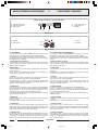
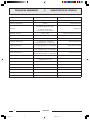
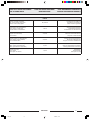
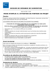
SERIE SERIES 8000 P8023 Equalizzatore grafico Graphic equaliser Égaliseur graphique ISTRUZIONI PER LUSO INSTRUCTIONS FOR USE MANUEL DUTILISATION SOMMARIO TABLE OF CONTENTS SOMMAIRE 1. Descrizione generale .................... 3 1. General description ...................... 3 1. Description générale .................... 9 1.1 Pannello frontale ................................ 3 1.1 Front panel ........................................ 3 1.1 Panneau frontal ................................. 9 1.2 Pannello posteriore ............................ 3 1.2 Rear panel ......................................... 3 1.2 Panneau postérieur ............................ 9 Recommandations générales ..... 10 2. Avvertenze generali ...................... 4 2. General warnings ......................... 4 2. 2.1 Installazione ...................................... 4 2.1 Installation ........................................ 4 2.1 Installation ...................................... 10 2.2 Alimentazione .................................... 4 2.2 Power supply ..................................... 4 2.2 Alimentation .................................... 10 2.3 Note di sicurezza ............................... 4 2.3 Safety notes ...................................... 4 2.3 Notes de sécurité ............................. 10 3. Connessioni e controlli ................. 5 3. Connections and controls ............. 5 3. Branchements et contrôles ........ 11 3.1 Esempio di installazione ..................... 5 3.1 Example of installation ....................... 5 3.1 Exemple d'installation ...................... 11 3.2 Collegamenti ...................................... 5 3.2 Connections ....................................... 5 3.2 Branchements .................................. 11 3.3 Principio di funzionamento ................. 6 3.3 Operating principle ............................. 6 3.3 Principe de fonctionnement .............. 12 4. Esempi di utilizzo .......................... 7 4. Examples of use ............................ 7 4. Exemple d'utilisation .................. 13 4.1 Equalizzatore dambiente .................... 7 4.1 Room equaliser .................................. 7 4.1 Égaliseur d'espace de diffusion ......... 13 4.2 Anti-Larsen ........................................ 7 4.2 Anti-Larsen ........................................ 7 4.2 Anti-Larsen ...................................... 13 5. Caratteristiche tecniche ............... 8 5. Technical specifications ............... 8 5. Caractéristiques techniques ....... 14 Lista delle parti di ricambio ................ 21 List of spare parts ............................... 21 Liste des pièces détachées ................. 21 Introduzione Nel ringraziarVi per aver scelto un prodotto PASO, vogliamo ricordarVi che la nostra azienda opera con sistema di qualità certificato UNI EN ISO 9002. I nostri prodotti vengono pertanto controllati in ogni fase della produzione per garantire la piena soddisfazione del Vostro acquisto. Per ogni evenienza la garanzia coprirà, nellanno di validità, eventuali difetti di fabbricazione. Per il corretto utilizzo di questo prodotto e per sfruttarne appieno le prestazioni vi raccomandiamo di leggere e seguire attentamente le istruzioni duso che seguono. Introduction While thanking you for having chosen a PASO product, we would like to remind you that our company works according to a Quality System certified for compliance with ISO 9002 standards. This means that all our products are checked during every phase of manufacturing in order to guarantee that you will be fully satisfied with your purchase. At all events, the guarantee will cover any manufacturing flaws for the whole year for which it is valid. We recommend that you read the following instructions for use carefully in order to exploit in full the performance of this product and to avoid any problems. Introduction Vous remerciant davoir accordé votre préférence à un produit PASO, nous tenons à vous rappeler que nous appliquons à notre production un Système Qualité certifié ISO 9002. Aussi, pour donner entière satisfaction à notre clientèle, tous nos produits sont contrôlés à chaque étape de la production. Ils sont en outre garantis contre tout défaut de fabrication pendant une période dun an. Nous vous recommandons de lire attentivement les instructions dinstallation et dutilisation qui suivent; elles vous permettront dobtenir le maximum des prestations offertes par le produit et en outre déviter tout problème. SERIE 8000 11-532.p65 1 1 26/06/01, 15.01 SERIE SERIES 8000 P8023 Grafik-Equalizer Grafische equalizer Ecualizador gráfico GEBRAUCHSANLEITUNG GEBRUIKSAANWIJZING INSTRUCCIONES DE EMPLEO INHALTSANGABE INHOUD SUMARIO 1. Allgemeine Beschreibung ............ 9 1. Algemene beschrijving .............. 15 1. Descripción general ................... 15 1.1 Frontpaneel ....................................... 9 1.1 Frontpaneel ..................................... 15 1.1 Panel frontal .................................... 15 1.2 Rückpaneel ....................................... 9 1.2 Achterpaneel ................................... 15 1.2 Panel trasero ................................... 15 2. Allgemeine Hinweise ................. 10 2. Algemene aanwijzingen ............ 16 2. Advertencias generales ............. 16 2.1 Installation ...................................... 10 2.1 Installatie ........................................ 16 2.1 Instalación ...................................... 16 2.2 Stromversorgung ............................. 10 2.2 Voeding ........................................... 16 2.2 Alimentación ................................... 16 2.3 Sicherheitshinweise ......................... 10 2.3 Veiligheidsvoorschriften ................... 16 2.3 Notas de seguridad ......................... 16 3. Anschlüsse und Kontrollen ........ 11 3. Aansluitingen en regelaars ........ 17 3. Conexiones y mandos ................ 17 3.1 Installationsbeispiel ......................... 11 3.1 Installatievoorbeeld ......................... 17 3.1 Ejemplo de instalación ..................... 17 3.2 Anschlüsse ...................................... 11 3.2 Aansluitingen .................................. 17 3.2 Conexiones ..................................... 17 3.3 Funktionsgrundregeln ...................... 12 3.3 Werkwijze ........................................ 18 3.3 Principio de funcionamiento ............. 18 4. Verwendungsbeispiele ............... 13 4. Voorbeelden van gebruik ........... 19 4. Ejemplos de utilización .............. 19 4.1 Raum-Equalizer ............................... 13 4.1 Equalizer van een ruimte ................. 19 4.1 Ecualizador de ambiente ................. 19 4.2 Anti-Larsen ...................................... 13 4.2 Anti-Larsen effect ............................ 19 4.2 Anti-Larsen ...................................... 19 5. Technische Eigenschaften ......... 14 5. Technische kenmerken .............. 20 5. Caracteristícas técnicas ............. 20 Ersatzteilliste ..................................... 21 Lijst vervangingsonderdelen ............. 21 Lista de las piezas de repuesto ......... 21 Einleitung Wir danken Ihnen für die Wahl eines PASO-Produkts und möchten Sie daran erinnern, daß wir mit dem anerkannten Qualitätssicherungssystem ISO 9002 arbeiten. D.h., alle unsere Produkte werden in jeder Fertigungsphase kontroll iert, um Ihre vollständige Zufriedenheit zu gewährleisten. Die einjährige Garantie deckt auf jeden Fall eventuell vorliegende Produktionsmängel ab. Wir empfehlen Ihnen, die hier vorliegende Bedienungsanweisung aufmerksam zu lesen, um das Leistungsangebot des Produktes voll nutzen zu können und um Probleme beim Gebrauch zu vermeiden. Inleiding Wij danken u voor uw keuze van een PASO product en herinneren u eraan dat de productie van ons bedrijf volgens een certificeerd kwaliteitssysteem ISO 9002 plaatsvindt. Onze producten worden daarom in iedere productiefase controleerd zodat u zeker tevreden zult zijn met uw aankoop. Eventuele fabrieksfoutjes zijn in het jaar dat de garantie geldig is, gedekt. Voor een goed gebruik van dit product en voor een volledige benutting van de prestaties hiervan, raden wij u aan onderstaande gebruiksvoorschriften met aandacht door te lezen. Introducción Les agradecemos que hayan elegido un producto PASO, y aprovechamos la ocasión para recordarles que nuestra empresa trabaja con el sistema de calidad certificado ISO 9002. Todos nuestros productos son controlados en cada fase de la producción para garantizarles una plena satisfacción en su adquisición. Para cualquier tipo de eventualidad la garantía cubrirá, durante el año de validez, los posibles defectos de fabricación. Les aconsejamos que lean detenidamente las siguientes instrucciones concernientes a la utilización, para aprovechar al máximo las prestaciones ofrecidas por este producto y para evitar eventuales problemas. SERIE 8000 2 11-532.p65 2 26/06/01, 15.01 DESCRIZIONE GENERALE 1 GENERAL DESCRIPTION L'equalizzatore grafico monocanale P8023 è dotato di 31 regolazioni a 1/3 ottava, che coprono la gamma 20 ÷ 20000 Hz. Impiegato tipicamente nei sistemi di rinforzo sonoro per la compensazione acustica degli ambienti, questo apparecchio puo' inoltre essere utilizzato come soppressore di retroazione acustica (effetto Larsen); caratteristica importante è l'elevato numero di regolazioni con filtri a banda molto stretta, che consente una elevata precisione nella messa a punto della risposta in frequenza complessiva del sistema impianto/ambiente. The P8023 single-channel graphic equaliser has 31 adjustment steps of one third of an octave, covering the range from 20 to 20000 Hz. Used typically in sound-reinforcement systems for acoustic compensation of rooms, this equipment can also be used as a suppressor of acoustic feedback (Larsen effect). An important feature is the high number of adjustments with filters having very narrow bandwidths, which enables very precise setting of the overall frequency response of the system/room. Ecco elencate le principali caratteristiche dell'equalizzatore: 31 filtri grafici ad 1/3 di ottava (copertura frequenze 20 ÷ 20000 Hz). possibilità di scelta nell'uso di segnali bilanciati o sbilanciati, sia in ingresso che in uscita; filtro subsonico (High pass) a 40 Hz con pendenza a 12 dB/oct; filtro ultrasonico (Low pass) a 16 KHz con pendenza a 12 dB/oct; range di escursione dei filtri selezionabile a ±6dB o ±12dB; pulsante di by-pass per poter verificare l'efficacia dell'equalizzazione; segnalazione luminosa di livello di ingresso e/o di uscita troppo elevati e, quindi, prossimi alla distorsione; deviatore per selezionare la massa elettrica (flottante/telaio); selettore protetto per l'alimentazione a 115 o 230 Vca, 50/60 Hz. attivazione automatica della modalità by-pass dell'apparecchio nel caso in cui l'alimentazione venga a mancare. Following is a list of the main features of the equaliser: 31 graphic filters, 1/3 of an octave each (covering the frequency range from 20 to 20000 Hz). possibility of choosing between the use of balanced or unbalanced signals, for both the input and the output signals; subsonic (Highpass) filter at 40 Hz with a slope of 12 dB/oct; ultrasonic (Lowpass) filter at 16 KHz with a slope of 12 dB/oct; range of travel of the filters selectable at ±6dB or ±12dB; by-pass button for checking the effectiveness of the equalisation; visual signalling of excessively high input and/or output level, which is therefore approaching distorsion; switch for selecting the electric earth (floating/frame); protected switch for 115 or 230 VAC, 50/60 Hz power supply. automatic activation of the by-pass mode of the equipment in case of power failure. 1.1 [1] [2] [3] [4] [5] [6] [7] [8] [9] PANNELLO FRONTALE Controlli di livello dei filtri. Controllo di livello generale. Pulsante dinserzione filtro passa-alto (40 Hz) e spia relativa. Pulsante dinserzione filtro passa-basso (16 kHz) e spia relativa. Spia rilevamento distorsione. Pulsante attivazione modalità bypass e spia relativa. Spie gamma di regolazione filtri (±6 dB / ±12dB). Pulsante per la selezione della gamma di regolazione dei filtri Interruttore di rete. 1.1 [1] [2] [3] [4] [5] [6] [7] [8] [9] FRONT PANEL Filter level controls. Overall level control. Push-button for highpass filter (40 Hz) and associated signalling lamp. Push-button for lowpass filter (16 kHz) and associated signalling lamp. Signalling lamp for detecting distortion. Push-button for bypass mode and associated signalling lamp. Signalling lamps for the filter adjustment range (±6 dB / ±12 dB). Pushbutton for selecting the filter adjustment range. Mains switch. 1.2 [10] [11] [12] [13] [14] [15] PANNELLO POSTERIORE Spina di rete con fusibile incorporato. Selettore della tensione di alimentazione. Connettori phono ingresso/uscita (collegamento sbilanciato). Connettori jack 1/4 ingresso/uscita (collegamento bilanciato). Connettori XLR ingresso/uscita (collegamento bilanciato). Deviatore selezione massa elettrica (flottante/telaio). 1.2 [10] [11] [12] [13] [14] [15] REAR PANEL Mains plug with built-in fuse. Switch for selecting the power-supply voltage. Phono input/output connectors (unbalanced connection). 1/4 input/output jacks (balanced connection). XLR input/output connectors (balanced connection). Switch for selecting electrical earthing (floating/frame). SERIE 8000 11-532.p65 3 3 26/06/01, 15.01 AVVERTENZE GENERALI 2 GENERAL WARNINGS 2.1 INSTALLAZIONE Tutti gli apparecchi PASO sono costruiti nel rispetto delle più severe normative internazionali di sicurezza ed in ottemperanza ai requisiti della Comunità Europea. Per un corretto ed efficace uso dellapparecchio è importante prendere conoscenza di tutte le caratteristiche leggendo attentamente le presenti istruzioni ed in particolare le note di sicurezza. Durante il funzionamento dellapparecchio è necessario assicurare unadeguata ventilazione. Evitare di racchiudere lapparecchio in un mobile privo di aerazione o di tenerlo in prossimità di sorgenti di calore. Questo apparecchio è predisposto per il montaggio in mobile rack standard 19. 2.1 INSTALLATION All PASO equipment is manufactured in accordance with the most stringent international safety standards and in compliance with European Community requisites. In order to use the equipment correctly and effectively, it is important to be aware of all its characteristics by reading these instructions and in particular the safety notes carefully. While the equipment is working, it is necessary to provide adequate ventilation. The equipment must not be closed inside cabinets without ventilation or kept in the vicinity of sources of heat. This equipment has provisions for mounting in a standard 19" rack. 2.2 ALIMENTAZIONE IMPORTANTE! Lapparecchio è predisposto di fabbrica per il funzionamento con tensione di rete a 230 V ± 10% 50/60 Hz (è comunque possibile anche il funzionamento a 115 V ± 10% 50/60 Hz). 2.2 POWER SUPPLY IMPORTANT! The equipment is factory set for operation at a power-supply voltage of 230 V ± 10% 50/60 Hz (operation at 115 V ± 10% 50/60 Hz is also possible). La modifica della tensione di alimentazione avviene tramite il selettore [15], protetto dall'apposita copertura. Lapparecchio é corredato di cavo di alimentazione con filo di terra ed il relativo terminale sulla spina di rete non deve essere rimosso in alcun caso. Assicurarsi che la presa di corrente sia dotata di collegamento di terra a norma di legge. The power-supply voltage is changed by means of the selector provided for this purpose [15], protected by a lid. The equipment is supplied with its own power supply cable which has an earth wire, and the associated terminal on the mains plug should never be removed in any case. Make sure that the power outlet is fitted with an earthing connection in accordance with the law. 2.3 NOTE DI SICUREZZA La rimozione del coperchio dell'apparecchio presenta il rischio di scosse elettriche. Ogni intervento all'interno dell'apparecchio deve essere eseguito da personale specializzato. All'interno non esistono regolazioni per l'utente. Prima di procedere alla sostituzione dei fusibili, accertarsi di avere staccato il cavo di rete. La sostituzione deve essere effettuata con fusibili dello stesso tipo e valore. Non rimuovere mai il conduttore di terra dal cavo di rete. Ad evitare il pericolo di scosse elettriche o guasti, non introdurre oggetti specialmente se metallici, attraverso le aperture dell'apparecchio. Nel caso di accidentale caduta di liquidi sull'apparecchio, staccare immediatamente la spina di rete ed interpellare il centro di assistenza PASO più vicino. 2.3 SAFETY NOTES Removal of the lid of the equipment entails the risk of electric shocks. Any activities inside the equipment should be carried out by specialised personnel only. There are no adjustments to be made by the user inside the equipment. Make sure that the power cable has been disconnected before proceeding to change the fuses. When replacing the fuses use new fuses of the same type and rating. Never remove the earth wire from the power cable. To avoid the danger of electric shocks or failures, do not introduce any objects, particularly not metal objects, into the openings in the equipment. If any liquid is accidentally spilt on the equipment, unplug it immediately from the mains and contact the nearest PASO Service Centre. SERIE 8000 4 11-532.p65 4 26/06/01, 15.01 CONNESSIONI E CONTROLLI 3 3.1 ESEMPIO DI INSTALLAZIONE L'equalizzatore grafico P8023 è tipicamente posto dopo il routing del segnale ed immediatamente prima delle unita' di potenza, in modo da sfruttare appieno sia l'elevata dinamica del segnale di uscita che le molteplici possibilita' di connessione (tre differenti tipologie di connettori e libera scelta nell'uso di segnali bilanciati o sbilanciati sia in ingresso che in uscita). Il posizionamento dell'apparecchio all'interno della catena di diffusione è illustrato nella figura 3.1.1. CONNECTIONS AND CONTROLS 3.1 EXAMPLE OF INSTALLATION Typically, the P8023 graphic equaliser is installed downstream from the signal routing and just before the power units, so as to exploit in full both the high dynamics of the output signal and the many options for connection (three different connector typologies and a free choice between the use of balanced or unbalanced signals both for the output and for the input). The position of the equipment within the broadcasting chain is illustrated in Figure 3.1.1. Fig. 3.1.1 3.2 COLLEGAMENTI L'equalizzatore P8023 offre all'utente la possibilità di scegliere, a seconda delle esigenze, tra un tipo di collegamento sbilanciato ed uno bilanciato. Sul pannello posteriore sono infatti presenti tre tipologie di connettori (XLR, jack 1/4" e phono) disponibili per le connessioni. Nelle figure seguenti vengono illustrate le caratteristiche di ciascuna presa. 3.2 CONNECTIONS The P8023 equaliser gives the user the possibility of choosing between an unbalanced or a balanced connection, depending on his specific requirements. There are three typologies of connectors available on the rear panel for the connections (XLR, 1/4" jack and phono). The characteristics of each socket are illustrated in the following figures. Collegamento bilanciato - Balanced connection 1 = Schermo 2 = Segnale (lato caldo) 3 = Segnale (lato freddo) 1 = Shield 2 = Signal (warm side) 3 = Signal (cold side) Fig. 3.2.1 SERIE 8000 11-532.p65 5 5 26/06/01, 15.01 CONNESSIONI E CONTROLLI 3 CONNECTIONS AND CONTROLS Collegamento bilanciato - Balanced connection 1 = Segnale (lato caldo) 2 = Segnale (lato freddo) 3 = Schermo 1 = Signal (warm side) 2 = Signal (cold side) 3 = Shield Fig. 3.2.2 Collegamento sbilanciato - Unbalanced connection 1 = Segnale 2 = Schermo 1 = Signal 2 = Shield Fig. 3.2.3 3.3 PRINCIPIO DI FUNZIONAMENTO Il cuore dellequalizzatore grafico P8023 è costituito da 31 filtri di tipo grafico ad 1/3 di ottava con frequenze centrali standard. Il campo di regolazione è definito dalla selezione di ±6dB o ±12dB. A completamento delle funzioni dellequalizzatore illustriamo i seguenti comandi e controlli: 3.3 OPERATING PRINCIPLE The heart of the P8023 graphic equaliser consists of 31 filters of the graphic type, each for one third of an octave, with standard central frequencies. The field of adjustment is defined by selecting either ±6 dB or ±12 dB. The following controls and monitoring facilities complete the functions of the equaliser: Controlli di livello dei filtri Ognuno di questi potenziometri lineari a slitta permette di regolare il livello di ciascun filtro e consente inoltre di avere una rappresentazione grafica della risposta in frequenza. Filter level controls Each of these sliding linear potentiometers can be used to adjust the level of each filter, and they also provide a "graphic" display of the frequency response. Controllo LEVEL Tramite questo controllo, è possibile impostare il livello del segnale di uscita dell'equalizzatore. Portando il cursore nella posizione intermedia 5, il guadagno della catena è unitario (con filtri tutti in posizione centrale). LEVEL control This control can be used to set the level of the output signal of the equaliser. With the cursor on the intermediate position, 5, the gain in the chain is even (when filters are all in the central position). Led CLIP L'accensione di questo led segnala la possibile distorsione del segnale nei diversi punti della catena amplificatrice. Per evitare questo tipo di problema, sarà necessario abbassare il controllo di livello [2]. Nel caso lindicazione persistesse, occorrerà diminuire anche il segnale di pilotaggio allingresso dellapparecchio. CLIP LED This LED lights up to indicate the possible distortion of the signal at the various points of the amplifying chain. To avoid this type of problem, it will be necessary to lower the level control [2]. If the signal persists, it will also be necessary to lower the level of the driving signal on the input of the equipment. Pulsante BYPASS Premendo questo pulsante, verrà inserita/disinserita la modalità Bypass. Quando questa modalità viene selezionata, il led relativo [6] si accende ed il segnale di ingresso viene deviato dalla catena amplificatrice ed inviato direttamente alluscita. Nel caso in cui l'alimentazione venga a mancare, un rele' interno attiva automaticamente la modalità Bypass. BYPASS push-button When this push-button is pressed, the Bypass mode will be activated/de-activated. If this mode has been selected, the associated LED [6] will light up and the input signal will be deviated from the amplifier chain and sent directly to the output. If there is a power failure, an internal relay will automatically activate the Bypass mode. Pulsante RANGE Questo pulsante permette di selezionare la gamma di regolazione dei filtri (±6dB o ±12dB). L'accensione dei leds indicherà la scelta effettuata. RANGE push-button This push-button can be used to select the filter adjustment range (±6 dB or ±12 dB). LED's will indicate which of them has been selected. Pulsante HI PASS Questo pulsante inserisce un filtro passa-alto nel percorso del segnale. Questo filtro opera tagliando le basse frequenze inferiori ai 40 Hz (12dB/ ottava). Il led relativo [3] si accenderà nel momento in cui il pulsante verrà premuto ed il filtro inserito. HI PASS push-button This push-button includes a highpass filter in the path of the signal. This filter works by cutting off the low frequencies below 40 Hz (12 dB/octave). The associated LED [3] will light up as soon as the push-button has been pressed and the filter has been included. Pulsante LOW PASS Questo pulsante inserisce un filtro passa-basso nel percorso del segnale. Questo filtro opera tagliando le alte frequenze superiori ai 16kHz (12dB/ ottava). Il led relativo [4] si accenderà nel momento in cui il pulsante verrà premuto ed il filtro inserito. LOW PASS push-button This push-button includes a lowpass filter in the path of the signal. This filter works by cutting off the high frequencies above 16 kHz (12 dB/octave). The associated LED [4] will light up as soon as the push-button has been pressed and the filter has been included. SERIE 8000 6 11-532.p65 6 26/06/01, 15.01 ESEMPI DI UTILIZZO 4 EXAMPLES OF USE 4.1 EQUALIZZATORE DAMBIENTE Dopo aver realizzato limpianto (come ad es. quello illustrato in fig. 3.1.1) ed effettuato le relative connessioni, procedere nel modo seguente: 1. Pilotare con sorgente di rumore rosa; 2. Verificare nei diversi punti dellambiente le risposte con un analizzatore di spettro audio. 3. Regolare i filtri in modo da ottenere una linearità di risposta in frequenza mediata nei diversi punti di misura. 4. Utilizzare frequentemente il pulsante BYPASS per escludere i filtri e verificarne leffetto sul segnale senza correzioni. 4.1 ROOM EQUALISER After setting up the system (e.g. similar to the one illustrated in Figure 3.1.1) and making the appropriate connections, proceed as follows: 1. Drive the system with a pink noise source; 2. Check the responses in various parts of the room using an audio spectrum analyser. 3. Adjust the filters in such a way as to obtain a mediated linearity of the frequency response at the various measuring points. 4. Use the BYPASS pushbutton frequently to exclude the filters so as to check the effect on the signals without any correction. 4.2 ANTI-LARSEN Dopo aver realizzato limpianto (come ad es. quello illustrato in fig. 3.1.1) ed effettuato le relative connessioni, procedere nel modo seguente: 1. Equalizzare il livello delle differenti sorgenti con una bassa potenza di uscita per non creare effetto Larsen. 2. Aumentare lentamente il volume dellunità di potenza fino al veficarsi della reazione elettroacustica. 3. Regolare i filtri della gamma relativi alla gamma di frequenza interessata tramite gli appositi cursori sullequalizzatore [1] al fine di annullare la reazione. 4. Aumentare nuovamente il volume sullunità di potenza e procedere nello stesso modo per correggere altre frequenze dinnesco. 5. Utilizzare frequentemente il pulsante BYPASS per escludere i filtri e verificarne leffetto sul segnale senza correzioni. 4.2 ANTI-LARSEN After setting up the system (e.g. similar to the one illustrated in Figure 3.1.1) and making the appropriate connections, proceed as follows: 1. Equalise the levels of the various different sources with a low output power, so as not to create any Larsen effect. 2. Increase the volume on the power unit gradually, until the electroacoustic reaction occurs. 3. Adjust the filters referred to the frequency range concerned by means of the appropriate cursors on the equaliser [1], in order to cancel out the reaction. 4. Increase the volume on the power unit again and proceed in the same way to correct other triggering frequencies. 5. Use the BYPASS pushbutton frequently to exclude the filters so as to check the effect on the signals without any correction. NOTE NOTES Si raccomanda di prendere nota delle posizioni dei vari cursori a correzione effettuata, evitando di modificarne la posizione per non alterare l'azione dell'equalizzatore. It is strongly recommended that you make a note of the positions of the various different cursors once the corrections have been carried out. Avoid changing their positions so as not to modify the action of the equaliser. In presenza di eventuali rumori di fondo, di risonananze acutissime o frequenze molto basse, utilizzare le funzioni HI PASS o LOW PASS per inserire i filtri relativi. Non eccedere nelle regolazioni dei filtri e mantenere fissi i cursori relativi alle frequenze non interessate dalla retroazione acustica. Non eccedere nella regolazione del comando LEVEL: deve essere utilizzato solo per compensare leventuale riduzione di livello sonoro operata dai filtri. If there is any background noise or very high resonance or if there are any very low frequencies, use the HI PASS or LOW PASS functions to include the appropriate filters. Do not adjust the filters excessively, and keep the cursors concerning the frequencies not affected by acoustic feedback in fixed positions. Do not adjust the LEVEL control too frequently. It should only be used to offset the lowering of the sound level caused by the filters. SERIE 8000 11-532.p65 7 7 26/06/01, 15.01 CARATTERISTICHE TECNICHE R i s p o s t a i n f r e q u e n z a ( ± 0 , 5 d B) 5 TECHNICAL SPECIFICATION 10 ÷ 50000 Hz F r e q u e n c y r e s p o n s e ( ± 0 , 5 d B) D i s t o r s i o n e ar m o n i ca ≤ 0,04% H ar m o n i c d i s t o r t i o n R a p p o r t o s eg n a l e/ d i s t u r b o ≥ 8 5 d BA S / N r at i o 3 1 f i l t r i a 1 / 3 d i o t t av a c o n f r eq u en z e c en t r a l i s t a n d a r d 3 1 f i l t er s a t 1 / 3 o c t a v e w i t h s t a n d a r d m ed i u m f r eq u en c i es R eg o l a z i o n i R a n g e d i r eg o l a z i o n e d ei f i l t r i A d j u s t m en t s ± 6dB o ± 12dB F i l t er s a d j u s t m en t r a n g e F i l t r o p a s s a - a l t o ( 3 d B) 4 0 H z ( 1 2 d B/ o c t ) H i g h - p a s s f i l t e r ( 3 d B) F i l t r o p a s s a - b a s s o ( 3 d B) 1 6 k H z ( 1 2 d B/ o c t ) L o w - p a s s f i l t e r ( 3 d B) 1 : 1 ( b i l a n c i a t o - b a l a n c ed ) 1 : 2 ( s b i l a n c i a t o - u n b a l a n c ed ) R a p p o r t o u s c i t a / i n g r es s o I n p u t / o u t p u t r at i o M a s s i m o s eg n a l e d ' i n g r es s o 1 4 V r m s ( b i l a n c i a t o - b a l a n c ed ) 7 V r m s ( s b i l a n c i a t o - u n b a l a n c ed ) M ax i m u m i n p u t s i g n al I m p ed en z a d ' i n g r es s o 1 5 k Ω ( b i l a n c i a t o - b a l a n c ed ) 1 0 k Ω ( s b i l a n c i a t o - u n b a l a n c ed ) I n p u t i m p ed a n c e 1 6 V r m s ( b i l a n c i a t o - b a l a n c ed ) 8 V r m s ( s b i l a n c i a t o - u n b a l a n c ed ) M ax i m u m o u t p u t s i g n al M a s s i m o s eg n a l e d ' u s c i t a 600 Ω I m p ed en z a d ' u s c i t a O u t p u t i m p ed a n c e L i v el l i d i s eg n a l a z i o n e C L I P i n g r es s o / i n p u t : 4 V r m s u s ci t a/ o u t p u t : 4 , 5 V r m s C L I P s i g n a l l i n g l ev el s A l i m en t a z i o n e 2 3 0 / 1 1 7 V ca, 5 0 / 6 0 H z P o w er s u p p l y 15 W C o n s u m p ti o n C o n su m o D i m en s i o n i ( L x A x P ) 480 x 44 x 220 m m D i m en s i o n s ( W x H x D ) D i m en s i o n i i m b a l l o ( L x A x P ) 540 x 95 x 265 m m P a c k a g e d i m en s i o n s ( W x H x D ) P es o ( n et t o ) 3 ,1 kg Wei g h t (n et) P es o ( i m b a l l a t o ) 3 ,4 kg Wei g h t (i n cl . p ack ag i n g ) SERIE 8000 8 11-532.p65 8 26/06/01, 15.01 DESCRIPTION GÉNÉRALE 1 ALLGEMEINE BESCHREIBUNG L'égaliseur graphique monocanal P8023 est doté de 31 réglages à 1/3 d'octave couvrant une gamme comprise entre 20 et 20000 Hz. Principalement utilisé sur les systèmes de renfort sonore pour la compensation acoustique d'espaces de diffusion, cet appareil peut également être utilisé comme suppresseur de rétroaction acoustique (effet Larsen); une des caractéristiques importantes de l'appareil est le nombre élevé de réglages dotés de filtres à bande très étroite, caractéristique permettant une grande précision dans la mise au point de la réponse en fréquence générale du système installation/espace. Der Monokanal-Grafik-Equalizer P8023 verfügt über 31 Einstellungen mit 1/3 Oktave, die den Frequenzbereich 20 ÷ 20000 Hz abdecken. Typischerweise wird das Gerät für die Tonverstärkung bei der Schallkompensierung in Räumen verwendet; das Gerät kann zudem auch für die Unterdrückung des Rückhallens (Larsen-Effekt) verwendet werden. Eine wichtige Eigenschaft ist wei terhin die hohe Anzahl der Einstellungsmöglichkeiten mit Hilfe von Filtern mit sehr engen Frequenzbereichen, aufgrund derer eine hohe Präzision bei der Regelung des Gesamtfrequenzgangs des Systems Anlage/Raum möglich ist. Principales caractéristiques de l'égaliseur: 31 filtres graphiques à 1/3 d'octave (couverture fréquences 20÷20000 Hz). possibilité d'utiliser au choix des signaux équilibrés ou déséquilibrés, aussi bien en entrée qu'en sortie. filtre passe-haut (High pass) à 40 Hz et pente à 12 dB/oct. filtre passe-bas (Low pass) à 16 kHz et pente à 12 dB/oct. plage d'excursion des filtres sélectionnables à ±6dB ou ±12dB. bouton de by-pass permettant de contrôler le bon fonctionnement de l'égaliseur. signal lumineux du niveau d'entrée et/ou de sortie trop élevé et proche de la distorsion. déviateur de sélection de la masse électrique (flottante/châssis). sélecteur protégé pour alimentation à 115 ou 230 Vca, 50/60 Hz. activation automatique de la modalité de by-pass de l'appareil en cas de coupure de courant. Nachstehend finden Sie die Haupteigenschaften des Equalizers: 31 grafische Filter mit 1/3 Oktave (Frequenzabdeckung 20÷20000 Hz); Auswahlmöglichkeit bezüglich des Einsatzes von symmetrischen und nicht symmetrischen Signalen sowohl am Eingang als auch am Ausgang; Unterschallfilter (Hochpass) mit 40 Hz und einer Neigung von 12 dB/Okt.; Ultraschallfilter (Tiefpass) mit 16 KHz und einer Neigung von 12 dB/Okt.; Bereich der auswählbaren Filter von ±6dB vìbis ±12dB; By-Pass-Taste für die Überprüfung der Einstellung des Ausgleichs; Leuchtanzeige für zu hohe Eingangs- und/oder Ausgangsstufeneinstellung, d.h. nahe des Verzerrungsbereichs; Weiche für die Wahl der elektrischen Masse (getrennte Masse für Netz und Signal/Rahmen); Geschützter Wählschalter für die Speisung mit 115 WS oder 230 WS, 50/60 Hz. Automatische Aktivierung der By-Pass-Modalität des Geräts bei Stromausfall. 1.1 [1] [2] [3] 1.1 [1] [2] [3] [7] [8] [9] PANNEAU FRONTAL Contrôles du niveau des filtres. Contrôle du niveau général. Bouton d'activation du filtre passe-haut (40 Hz) avec témoin correspondant. Bouton d'activation du filtre passe-bas (16 kHz) avec témoin correspondant. Témoin indicateur de distorsion. Bout o n d ' a c t i va t i o n d e l a m o d a l i t é b y - p a s s e t t é m o i n correspondant. Témoins gamme de réglage des filtres (±6 dB / ±12dB). Bouton de sélection de la gamme de réglage des filtres. Interrupteur alimentation de secteur. 1.2 [10] [11] [12] [13] [14] [15] PANNEAU POSTÉRIEUR Fiche de secteur à fusible incorporé. Sélection de la tension d'alimentation. Connecteurs phono entrée/sortie (raccordement déséquilibré). Connecteurs jack 1/4" entrée /sortie (raccordement équilibré). Connecteurs XLR entrée /sortie (raccordement équilibré). Déviateur de sélection masse électrique (flottante/châssis). 1.2 [10] [11] [12] [4] [5] [6] [4] [5] [6] [7] [8] [9] FRONTPANEEL Stufenkontrolle Filter. Allgemeine Stufenkontrolle. Einschalttaste für den Hochpassfilter (40 Hz) und die entsprechende Kontrollleuchte. Einschalttaste für den Tiefpassfilter (16 kHz) und die entsprechende Kontrollleuchte. Kontrollleuchte für die Verzerrungsermittlung. Taste für die Aktivierung der Modalität Bypass und der entsprechenden Kontrollleuchte. Bereichs-Kontrollleuchten für die Filtereinstellung (±6 dB / ±12dB). Taste für die Auswahl des Filtereinstellungsbereichs. Netzschalter. RÜCKPANEEL Netzstecker mit integrierter Sicherung. Wählschalter für die Versorgungsspannung. Phono-Anschlussstücke Eingang/Ausgang (nicht symmetrischen Verbindung). [13] Jack-Anschlüsse 1/4" Eingang/Ausgang (symmetrische Verbindung). [14] XLR-Anschlussstücke Eingang/Ausgang (symmetrische Verbindung) [15] Auswahl-Weiche elektrische Masse (getrennte Masse für Netz und Signal/Rahmen). SERIE 8000 11-532.p65 9 9 26/06/01, 15.01 RECOMMANDATIONS GÉNÉRALES 2 ALLGEMEINE HINWEISE 2.1 INSTALLATION Tous les appareils PASO sont réalisés dans le respect des normes internationales de sécurité les plus sévères et conformément à tous les standards de l'Union européenne. Pour garantir le bon fonctionnement de l'appareil, il est important de prendre connaissance de toutes ses caractéristiques, en lisant à cet effet les présentes instructions en accordant une attention toute particulière aux notes de sécurité. Durant le fonctionnement de l'appareil, il est nécessaire de garantir une bonne ventilation et il est important d'éviter de placer l'appareil dans un meuble dépourvu d'aération ou encore de le placer à proximité de sources de chaleur. Cet appareil est prévu pour être monté dans un meuble rack standard de 19. 2.1 INSTALLATION Alle PA SO-Geräte werden nach strengsten internationalen Sicherheitsvorschriften und unter Beachtung der Anforderungen der EU gefertigt. Zum Zweck eines ordnungsgemäßen und wirksamen Einsatzes des Geräts ist es wichtig, die vorliegende Gebrauchsanweisung und insbesondere die Sicherheitshinweise zu lesen, um sämtliche Geräteeigenschaften zu kennen. Während des Betriebs des Geräts ist es erforderlich, eine ausreichende Ventilierung sicherzustellen, d.h. zu vermeiden, das Gerät in einem nicht belüfteten Schrank oder in der Nähe von Wärmequellen aufzustellen. Das Gerät ist für die Montage in einem 19"-Standard-Rack konzipiert. 2.2 ALIMENTATION IMPORTANT! L'appareil est prévu pour être alimenté à une tension de secteur de 230V ± 10% 50/60 Hz (il peut également être alimenté à une tension de secteur de 115 V ± 10% 50/60 Hz). 2.2 STROMVERSORGUNG WICHTIG! Das Gerät ist für den Betrieb mit einer Netzspannung von 230 V ± 10% 50/60 Hz konzipiert (außerdem ist der Betrieb mit 115 V ± 10% 50/60 Hz) möglich. La modification de la tension d'alimentation s'effectue par l'intermédiaire du sélecteur [15], lequel est doté d'une protection. Die Änderung der Versorgungsspannung erfolgt mittels des Wählschalters [15], der mit einer Schutzabdeckung versehen ist. L'appareil est fourni avec un câble d'alimentation pourvu de conducteur et de broche pour la mise à la terre, cette broche ne doit en aucun cas être retirée. S'assurer que la prise de courant est bien raccordée à une ligne de mise à la terre conforme à la réglementation. Das Gerät ist mit einem Stromkabel mit Erdschutzleiter ausgerüstet, das entsprechende Terminal am Netzstecker darf auf gar keinen Fall entfernt werden. Stellen Sie sicher, dass die Steckdose einen normentsprechenden Anschluss besitzt. 2.3 NOTES DE SÉCURITÉ Le retrait du couvercle de l'appareil expose au risque de décharge électrique. Toute intervention effectuée à l'intérieur de l'appareil doit être confiée à un personnel spécialisé. La partie interne de l'appareil ne renferme aucun réglage destiné à l'utilisateur. Avant de procéder au changement des fusibles, s'assurer que l'appareil a bien été isolé du secteur d'alimentation en ayant débranché à cet effet la prise correspondante. Il est important de veiller à ce que les fusibles soient remplacés par des fusibles de type et d'ampérage identiques. Ne jamais retirer le conducteur de mise à la terre présent sur le câble d'alimentation. Afin de prévenir tout risque de décharge électrique ou autre anomalie, ne jamais introduire des objets, en particulier métalliques, à travers les ouvertures de l'appareil. Dans le cas où un liquide serait involontairement renversé sur l'appareil, débrancher immédiatement la prise du secteur d'alimentation et prendre contact avec le Centre d'assistance PASO le plus proche. 2.3 SICHERHEITSHINWEISE Wenn die Abdeckung des Geräts entfernt wird, besteht Stromschlaggefahr. Jeder Eingriff im Geräteinnern muss von Fachpersonal durchgeführt werden. Im Innenraum sind keine anwenderseitig regulierbaren Einstellungen vorhanden. Vor Auswechseln der Sicherungen, muss sichergestellt werden, dass der Netzstecker abgezogen wurde. Die Sicherungen müssen mit neuen Sicherungen gleichen Typs und Wertes ersetzt werden. Der Erdschutzleiter darf niemals vom Netzkabel entfernt werden. Zur Vermeidung von Stromschlägen und Schäden dürfen keine Gegenstände, insbesondere Metallgegenstände durch die Öffnungen des Geräts in den Innenraum eingeführt werden. Im Fall von Ausfließen von Flüssigkeiten auf dem Gerät muss der Netzstecker sofort abgezogen und das am nächsten gelegene PASO-Kundendienstzentrum verständigt werden. SERIE 8000 10 11-532.p65 10 26/06/01, 15.01 BRANCHEMENTS ET CONTRÔLES 3 3.1 EXEMPLE D'INSTALLATION L'égaliseur graphique P8023 est généralement installé en aval du routage du signal et juste en amont des unités de puissance, de façon à exploiter au mieux la haute dynamique du signal de sortie et les multiples possibilités de connexion (trois types différents de connecteur et possibilité d'utiliser indifféremment des signaux équilibrés et des signaux déséquilibrés, aussi bien en entrée qu'en sortie). Le positionnement de l'appareil sur la chaîne de diffusion est montré par la figure 3.1.1. ANSCHLÜSSE UND KONTROLLEN 3.1 INSTALLATIONSBEISPIEL Der Grafik-Equalizer P8023 wird typischerweise nach dem Signal-Routing gesetzt und unmittelbar hinter der Leistungseinheit, so dass die hohe Dynamik des Ausgangssignals sowie die Vielzahl der Anschlussmöglichkeiten (drei verschiedene Arten von Anschlüssen und freie Auswahl beim Einsatz von symmetrischen und nicht symmetrischen Signalen sowohl am Eingang, als auch am Ausgang) voll genutzt werden können. Die Position des Geräts innerhalb der Reihenschaltung des Beschallungssystems ist in der Abbildung 3.1.1 dargestellt. Fig./Abb. 3.1.1 3.2 BRANCHEMENTS L'égaliseur graphique P8023 offre à l'utilisateur la possibilité, selon les besoins spécifiques, de choisir ou bien un branchement déséquilibré ou bien un branchement équilibré. Sur le panneau postérieur sont en effet présents trois types de connecteurs (XLR, jack 1/4 et phono) pour les différentes connexions (voir les figures suivantes). 3.2 ANSCHLÜSSE Der Grafik-Equalizer P8023 bietet dem Anwender die Möglichkeit, je nach Erfordernis zwischen einem symmetrischen und einem nicht symmetrischen Anschluss auszuwählen. Auf dem Rückpaneel befinden sich hierfür drei Arten von Anschlussstücken (XLR, Jack 1/4 und Phono) für die entsprechenden Verbindungen. Die Abbildung zeigt die Eigenschaften einer jeden Buchse. Raccordement équilibrée - Symmetrischen Verbindung 1 = Blindage 2 = Signal (côté chaud) 3 = Signal (côté froid) 1 = Abschirmung 2 = Signal (warme Seite) 3 = Signal (kalte Seite) Fig./Abb. 3.2.1 SERIE 8000 11-532.p65 11 11 26/06/01, 15.01 BRANCHEMENTS ET CONTRÔLES 3 ANSCHLÜSSE UND KONTROLLEN Raccordement équilibrée - Symmetrischen Verbindung 1 = Signal (côté chaud) 2 = Signal (côté froid) 3 = Blindage 1 = Signal (warme Seite) 2 = Signal (kalte Seite) 3 = Abschirmung Fig./Abb. 3.2.2 Raccordement déséquilibrée - Nicht symmetrischen Verbindung 1 = Signal 2 = Blindage 1 = Signal 2 = Abschirmung Fig./Abb. 3.2.3 3.3 PRINCIPE DE FONCTIONNEMENT Le cur de l'égaliseur graphique P8023 est constitué de 31 filtres de type graphique à 1/3 d'octave et fréquences centrales standard. La plage de réglage est définie par le sélection de ±6dB ou ±12dB. Pour décrire de manière exhaustive les fonctions de l'égaliseur, ci-après en sont décrits les commandes et les contrôles: 3.3 FUNKTIONSGRUNDREGELN er Schlüsselmechanismus des Grafik-Equalizers P8023 besteht aus 31 Grafik-Filtern mit 1/3 Oktave und Standard Zentralfrequenzen. Der Einstellungsbereich wird durch die Wahl des Bereichs ±6dB oder ±12dB bestimmt. Zur Vervollständigung der Funktionalitäten des Equalizers erläutern wir die folgenden Befehle und Kontrollen: Contrôles de niveau des filtres Chacun de ces potentiomètres linéaires à glissière permet de régler le niveau de chaque filtre et d'obtenir en outre une représentation "graphique" de la réponse en fréquence. Filterstufen-Kontrolle Jedes dieser linearen Schiebepotentiometer ermöglicht die Stufeneinstellung der einzelnen Filter und zudem auch die grafische Abbildung des Frequenzgangs. Contrôle LEVEL ar l'intermédiaire de ce contrôle, il est possible de régler le niveau du signal de sortie de l'égaliseur. En amenant le curseur dans la position intermédiaire 5, le gain de la chaîne est unitaire (ensemble des filtres en position centrale). Kontrolle LEVEL Mit Hilfe dieser Kontrolle kann die Signalstufe des Ausgangs des Equalizers eingestellt werden. Wenn man den Cursor auf die mittlere Position 5 setzt, erfolgt eine Gesamtverstärkung der Lautsprecherleitung (alle Filter in mittiger Stellung). Voyant CLIP Allumé, ce voyant indique une possible distorsion du signal sur les différents points de la chaîne d'amplification. Pour prévenir ce type de problème, il est nécessaire d'abaisser le contrôle de niveau [2]. Dans le cas où le problème persisterait, il est nécessaire d'abaisser également le signal de commande à l'entrée de l'appareil. Led CLIP Das Aufleuchten dieses Leds gibt die mögliche Verzerrung des Signals an den unterschiedlichen Punkten der Verstärkerleitung an. Zur Vermeidung dieses Problems ist es erforderlich, die Stufenkontrolle [2] niedriger einzustellen. Falls die Anzeige weiterhin leuchten sollte, muss auch das Steuersignal am Eingang des Gerätes niedriger eingestellt werden. Bouton BYPASS Ce bouton permet d'activer/désactiver la modalité de by-pass. Lorsque cette modalité est sélectionnée, le voyant [6] est allumé et le signal d'entrée est dévié de la chaîne d'amplification et directement dirigé vers la sortie. En cas de coupure de courant, un relais interne active automatiquement la modalité de by-pass. Bouton RANGE Ce bouton permet de sélectionner la gamme de réglage des filtres (±6dB ou ±12dB). Le voyants s'allument, selon la sélection effectuée. Bouton HI PASS Ce bouton permet d'activer un filtre passe-haut sur le parcours du signal. Ce filtre retient les basses fréquences inférieures à 40 Hz (12dB/octave). Le voyant [3] correspondant s'allume après avoir appuyé sur le bouton et activé le filtre. Bouton LOW PASS Ce bouton permet d'activer un filtre passe-bas sur le parcours du signal. Ce filtre retient les hautes fréquences supérieures à 16 kHz (12dB/octave). Le voyant [4] correspondant s'allume après avoir appuyé sur le bouton et activé le filtre. Taste RANGE Diese Taste ermöglicht die Auswahl des Einstellungsbereichs der Filter (±6dB oder ±12dB). Das Aufleuchten der Leds zeigt die getätigte Auswahl an. Taste HI PASS Diese Taste setzt einen Hochpassfilter in den Signalverlauf ein. Der Filter schneidet die Frequenzen unterhalb von 40 Hz (12dB/Oktaven) ab. Das zugehörige Led [3] leuchtet dann auf, wenn die Taste Betätigt und der Filter eingeschaltet wird. Taste LOW PASS Diese Taste aktiviert einen Tiefpassfilter an der Signalleitung. Der Filter schneidet hohe Frequenzen über 16kHz (12dB/Oktave) ab. Das entsprechende Led [4] leuchtet dann auf, wenn die Taste betätigt und der Filter eingeschaltet wird. SERIE 8000 12 11-532.p65 Taste BYPASS Bei Betätigen dieser Taste, wird die Modalität Bypass aktiviert/deaktiviert. Bei Auswahl dieser Modalität leuchtet das entsprechende Led [6] auf und das Eingangssignal wird von der Verstärkerleitung abgezweigt und direkt an den Ausgang gesandt. Bei Stromausfall aktiviert ein internes Relais direkt die Bypass- Modalität. 12 26/06/01, 15.01 EXEMPLES D'UTILISATION 4 VERWENDUNGSBEISPIELE 4.1 ÉGALISEUR D'ESPACE DE DIFFUSION Une fois l'installation réalisée (par exemple telle que celle montrée à la fig. 3.1.1) et après avoir réalisé les branchements nécessaires, procéder comme suit: 1. Piloter avec une source de bruit rose. 2. Contrôler les réponses sur les différents points de l'espace de diffusion à l'aide d'un analyseur de spectre audio. 3. Régler les filtres de façon à obtenir une réponse en fréquence linéaire médiate à hauteur des différents points de mesure. 4. Utiliser fréquemment le bouton de BY-PASS pour désactiver les filtres et contrôler ainsi l'effet sur le signal sans correction. 4.1 RAUM-EQUALIZER Nach Einrichtung der Anlage (wie bspw. nach Abbildung 3.1.1) und Herstellung der Anschlüsse, wird wie folgt verfahren: 1. Steuerung mit Rosa-Rauschen; 2. Überprüfung des Frequenzgangs an verschiedenen Punkten im Raum mit Hilfe eines Tonspektrumanalysegeräts. 3. Einstellung der Filter, so dass der an den unterschiedlichen Messpunkten erhobene Frequenzgang linear ist. 4. Häufige Verwendung der Taste BYPASS für den Ausschluss von Filtern und die Überprüfung der entsprechenden Wirkung auf das Signal ohne Korrekturen. 4.2 ANTI-LARSEN Une fois l'installation réalisée (par exemple telle que celle montrée à la fig. 3.1.1) et après avoir réalisé les branchements nécessaires, procéder comme suit: 1. Égaliser le niveau des différentes sources à basse puissance de sortie pour éviter l'effet de Larsen. 2. Augmenter lentement le volume de l'unité de puissance jusqu'à ce que se produise l'effet de rétroaction acoustique. 3. Régler les filtres de la gamme correspondante à la gamme de fréquence concernée par l'intermédiaire des curseurs présents sur l'égaliseur [1] afin d'éliminer l'effet de rétroaction acoustique. 4. Augmenter à nouveau le volume sur l'unité de puissance et procéder comme indiqué plus haut pour corriger d'autres fréquences de déclenchement. 5. Utiliser fréquemment le bouton de BY-PASS pour désactiver les filtres et contrôler ainsi l'effet sur le signal sans correction. 4.2 ANTI-LARSEN Nach Einrichtung der Anlage (wie bspw. nach Abbildung 3.1.1) und Herstellung der entsprechenden Verbindungen, muss wie folgt verfahren werden: 1. Ausgleich der unterschiedlichen Tonquellen mit Hilfe einer niedrigen Ausgangsleistung zur Vermeidung des Rückhallens (Larsen). 2. Langsames Anheben der Lautstärke der Leistungseinheit, bis die elektroakustische Wirkung einstellt. 3. Regulierung der Filter des betroffenen Frequenzbereichs mit Hilfe der Cursors am Equalizer [1] , um die Wirkung zu eliminieren. 4. Erneute Erhöhung der Lautstärke an der Leistungseinheit und Wiederholung des Vorgangs für die Korrektur anderer Einschaltfrequenzen. 5. Häufige Betätigung der Taste BYPASS zum Ausschluss von Filtern und Überprüfung der entsprechenden Wirkung auf das Signal ohne Korrekturmaßnahmen. NOTES HINWEISE Il est recommandé de prendre note des positions des différents curseurs une fois la correction effectuée et d'éviter d'en modifier la position pour ne pas altérer l'effet obtenu grâce à l'égalisateur. Es wird empfohlen, nach vorgenommener Korrektur die Stellung der Schieber zu notieren und die Änderung deren Stellungen zu vermeiden, um den Betrieb des Equalizers nicht zu ändern. En présence de bruits de fond importants, de résonances très aiguës ou de fréquences particulièrement basses, activer les functions HI PASS ou LOW PASS en appuyant sur les boutons correspondants. Bei eventuellen Nebengeräuschen, Hochton-Resonanzen oder sehr niedrigen Frequenzen, müssen die Tasten HI PASS oder LOW PASS betätigt werden, um die entsprechenden Filter zu aktivieren. Ne pas excéder au niveau du réglage des filtres et ne pas modifier la position des curseurs aux fréquences non sujettes à la rétroaction acoustique. Vermeiden Sie eine exzessive Regulierung der Filter und ändern Sie die Schieber nicht, die vom akustischen Widerhall nicht betroffen sind. Ne pas excéder au niveau du réglage de la commande LEVEL: elle doit être utilisée exclusivement pour compenser la réduction du niveau sonore produite par l'action des filtres. Vermeiden Sie eine exzessive Regelung der Kontrolle LEVEL: die Kontrolle wird nur für den Ausgleich der von den Filtern bewirkten Tonstufenreduzierung verwendet. SERIE 8000 11-532.p65 13 13 26/06/01, 15.01 CARACTÉRISTIQUES TECHNIQUES R é p o n s e e n f r é q u e n c e ( ± 0 , 5 d B) 5 TECHNISCHE EIGENSCHAFTEN 10 ÷ 50000 Hz F r e q u e n z g a n g ( ± 0 , 5 d B) D i s t o r s i o n h ar m o n i q u e ≤ 0,04% O b er w el l en v er z er r u n g R ap p o r t s i g n al / b r u i t ≥ 8 5 d BA S t ö r ab s t an d 3 1 f i l t r es à 1 / 3 d ' o c t a v e à f r éq u en c es c en t r a l es s t a n d a r d 1 F i l t er m i t 1 / 3 O k t a v e m i t S t a n d a r d - Z en t r a l f r eq u en z en R ég l a g es P l a g e d e r ég l a g e d es f i l t r es E i n s t el l u n g en ± 6dB o ± 12dB F i l t er ei n s t el l u n g s b er ei c h F i l t r e p a s s e - h a u t ( 3 d B) 4 0 H z ( 1 2 d B/ o c t ) H o c h p a s s f i l t e r ( 3 d B) F i l t r e p a s s e - b a s ( 3 d B) 1 6 k H z ( 1 2 d B/ o c t ) T i e f p a s s f i l t e r ( 3 d B) 1 : 1 ( éq u i l i b r é - s y m m et r i s c h ) 1 : 2 ( d és éq u i l i b r é - n i c h t s y m m et r i s c h ) R a p p o r t s o r t i e/ en t r ée Ver h äl tn i s Ei n g an g /A u sg an g S i g n a l d ' en t r ée m a x i m u m 1 4 V r m s ( éq u i l i b r é - s y m m et r i s c h ) 7 V r m s ( d és éq u i l i b r é - n i c h t s y m m et r i s c h ) M a x i m a l es E i n g a n g s s i g n a l I m p éd a n c e d ' en t r ée 1 5 k Ω ( éq u i l i b r é - s y m m et r i s c h ) 1 0 k Ω ( d és éq u i l i b r é - n i c h t s y m m et r i s c h ) E i n g a n g s i m p ed a n z 1 6 V r m s ( éq u i l i b r é - s y m m et r i s c h ) 8 V r m s ( d és éq u i l i b r é - n i c h t s y m m et r i s c h ) M a x i m a l es A u s g a n g s s i g n a l S i g n al d e s o r t i e m ax i m u m I m p éd a n c e d e s o r t i e N i v ea u x d e s i g n a l C L I P A l i m en t a t i o n 600 Ω A u s g a n g s i m p ed a n z en t r ée/ ei n g a n g : 4 V r m s s o r t i e/ a u s g a n g : 4 , 5 V r m s A n z ei g es t u f en C L I P 2 3 0 / 1 1 7 V ca, 5 0 / 6 0 H z C o n s o m m at i o n S t r o m v er s o r g u n g 15 W Ver b r au ch D i m en s i o n s ( L x H x P ) 480 x 44 x 220 m m A b m es s u n g en ( L x H x T ) D i m en s i o n s em b a l l a g e ( L x H x P ) 540 x 95 x 265 m m A b m essu n g en d er Ver p ack u n g (L x H x T ) P o i d s ( n et ) 3 ,1 kg G ew i c h t ( n et t o ) P o i d s ( em b a l l é) 3 ,4 kg G ew i ch t (m i t Ver p ack u n g ) SERIE 8000 14 11-532.p65 14 26/06/01, 15.01 ALGEMENE BESCHRIJVING 1 DESCRIPCIÓN GENERAL De enkelkanaals grafische equalizer P8023 is voorzien van 31 instellingen van 1/3 octaaf, waarmee de gamma 20 ÷ 20000 Hz wordt bestreken. D it apparaat, met name ingezet binnen geluidsversterkingssystemen ten behoeve van de akoestische compensatie van ruimten, kan bovendien ook worden gebruikt ter onderdrukking van de gehoorterugkoppeling (Larsen-effect); een belangrijk kenmerk is het hoge aantal instellingen met behulp van zeer smalbandige filters, waardoor een zeer grote nauwkeurigheid bereikt kan worden bij het afstellen van de algehele frequentieresponsie van het systeem installatie/ruimte. El ecualizador gráfico monocanal P8023 dispone de 31 regulaciones de 1/3 de octava, que abarcan la gama 20 ÷ 20000 Hz. Normalmente utilizado en los sistemas de refuerzo sonoro para la compensación acústica de los ambientes, este aparato también puede ser utilizado como supresor de retroacción acústica (efecto Larsen); característica importante es el alto número de regulaciones con filtros de banda muy estrecha, que permite conseguir una alta precisión en la puesta a punto de la respuesta en frecuencia global del sistema instalación/ ambiente. Hieronder staan de hoofdkenmerken van de equalizer: 31 grafische filters van 1/3 octaaf (dekking van 20 ÷ 20000 Hz frequenties). mogelijkheid om te kiezen tussen signalen van het gebalanceerde of het niet gebalanceerde type, ingangssignalen zowel als uitgangssignalen. subsonische filter (High pass) van 40 Hz met pendentie van 12 dB/oct; ultrasonische filter (Low pass) van 16 KHz met pendentie van 12 dB/oct; bereik van filters instelbaar op ±6dB of ±12dB; by-passknop om te kunnen controleren of de vereffening goed werkt. lichtsignaal bij een te hoog ingangs- en/of uitgangsniveau, waardoor het geluid kan worden vervormd schakelaar voor het selecteren van de elektrische massa (fluctuerend/frame); beveiligde keuzeschakelaar voor voeding van 115 of 230 Vca, 50/60 Hz. automatische activering van by-passinstelling van het apparaat voor het geval dat de voeding wordt onderbroken. He aquí las características principales del ecualizador: 31 filtros gráficos de 1/3 de octava (rango frecuencias 20 ÷ 20000 Hz). posibilidad de seleccionar en el uso señales balanceadas o no balanceadas, tanto en entrada como en salida; filtro subsónico (High pass) a 40 Hz con pendiente de 12 dB/oct; filtro ultrasónico (Low pass) a 16 KHz con pendiente de 12 dB/oct; rango de variación de los filtros seleccionable en ±6dB ó ±12dB; pulsador de by-pass para poder verificar la eficacia de la ecualización; señalización luminosa de nivel de entrada y/o de salida demasiado altos y por tanto próximos a la distorsión; desviador para seleccionar la masa eléctrica (flotante/bastidor); selector protegido para la alimentación a 115 ó 230 Vca, 50/60 Hz; activación automática de la modalidad by-pass del aparato en caso de falta de alimentación. 1.1 [1] [2] [3] FRONTPANEEL Niveauregelaars filters. Algemene niveauregelaar. Inschakelknop hoogdoorlaatfilter (40 Hz) en betreffende controlelamp. Inschakelknop laagdoorlaatfilter (16 kHz) en betreffende controlelamp. Controlelamp vervorming. Drukknop activering van by-passmode en betreffende controlelamp. Controlelampen gamma filterinstelling (±6 dB / ±12dB). Drukknop voor het selecteren van gamma filterinstelling. Netschakelaar. 1.1 [1] [2] [3] [5] [6] [7] [8] [9] PANEL FRONTAL Mandos de nivel de los filtros. Mando de nivel general. Pulsador de activación filtro paso-alto (40 Hz) y correspondiente chivato. Pulsador de activación filtro paso-bajo (16 KHz) y correspondiente chivato. Chivato detección distorsión. Pulsador activación modalidad bypass y correspondiente chivato. Chivatos rango de regulación filtros (±6 dB / ±12dB). Pulsador para seleccionar la gama de regulación de los filtros. Interruptor de red. ACHTERPANEEL Netstekker met ingebouwde zekering. Schakelaar voedingsspanning. Phono-connectors ingang/uitgang (niet-gebalanceerde aansluiting). Jack 1/4" connectors ingang/uitgang (gebalanceerde aansluiting). XLR connectors ingang/uitgang (gebalanceerde aansluiting). Schakelaar voor het selecteren van elektrische massa (fluctuerend/frame). 1.2 [10] [11] [12] [13] [14] [15] PANEL TRASERO Clavija de red con fusible incorporado. Selector de la tensión de alimentación. Conectadores phono entrada/salida (conexión no balanceada). Conectadores jack 1/4" entrada/salida (conexión balanceada). Conectadores XLR entrada/salida (conexión balanceada). Desviador selección masa eléctrica (flotante/bastidor). [4] [5] [6] [7] [8] [9] 1.2 [10] [11] [12] [13] [14] [15] [4] SERIE 8000 11-532.p65 15 15 26/06/01, 15.01 ALGEMENE AANWIJZINGEN 2 ADVERTENCIAS GENERALES 2.1 INSTALLATIE Al het apparatuur van PASO is vervaardigd met inachtneming van de internationale wettelijke veiligheidsvoorschriften en overeenkomstig de vereisten van de Europese Gemeenschap. Voor een correct en doelmatig gebruik van het apparaat is het van belang kennis te nemen van alle kenmerken ervan en de bijgaande aanwijzingen aandachtig te lezen, waarbij bijzondere aandacht aan de veiligheidsregels dient te worden besteed. Wanneer het apparaat aan staat, dient voor een adequate ventilatie te worden gezorgd. Sluit het apparaat niet op in een niet-geventileerde kast en plaats het nooit in de nabijheid van warmtebronnen. Dit apparaat kan in een standaard 19 rack kast worden geïnstalleerd. 2.1 INSTALACIÓN Todos los aparatos PASO están fabricados conforme a las más severas normas internacionales de seguridad y según los requisitos de la Comunidad Europea. Para una utilización correcta y eficaz del aparato es importante tener conocimiento de todas las características, leyendo detenidamente estas instrucciones y en particular las notas de seguridad. Durante el funcionamiento del aparato es necesario asegurar una adecuada ventilación, evitando encerrar el aparato en un mueble sin ventilación o ponerlo cerca de fuentes de calor. Este aparato está predispuesto para el montaje en mueble rack standard 19. 2.2 VOEDING BELANGRIJK! Het apparaat is geschikt om te functioneren op een netspanning van 230 V ± 10% 50/60 Hz (en kan bovendien ook op 115 V ± 10% 50/60 Hz werken). 2.2 ALIMENTACIÓN ¡IMPORTANTE! El aparato está predispuesto para el funcionamiento con tensión de red a 230 V ± 10% 50/60 Hz (también es posible el funcionamiento a 115 V ± 10% 50/60 Hz). De voedingsspanning kan met behulp van een, met een speciaal deksel beschermde, schakelaar [15] worden gewijzigd. La modificación de la tensión de alimentación se realiza mediante el selector [15], protegido por la cobertura correspondiente. Het apparaat is voorzien van een voedingskabel met aarddraad en de overeenkomstige klem op de netstekker mag in geen enkel geval worden verwijderd. Ga na of het stopcontact overeenkomstig de wettelijke voorschriften geaard is. El aparato viene provisto de cable de alimentación con hilo de conexión a tierra y no se debe nunca quitar el terminal correspondiente de la clavija. Comprobar que la toma de corriente disponga de conexión a tierra conforme a las normas de ley. 2.3 VEILIGHEIDSVOORSCHRIFTEN Het verwijderen van het deksel van het apparaat kan gevaar van elektrische schokken opleveren. Alle werkzaamheden in het binnenste van het apparaat mogen uitsluitend worden uitgevoerd door gespecialiseerde technici. Binnenin het apparaat bevinden zich geen instelknoppen voor de gebruiker. Alvorens de zekeringen te vervangen, dient u altijd na te gaan of de netkabel is afgekoppeld. De zekeringen dienen te worden vervangen met zekeringen van hetzelfde type en dezelfde waarde. Verwijder nooit de aarddraad uit de netkabel. Breng nooit voorwerpen, zeker geen metalen voorwerpen, naar binnen via de openingen in het apparaat, ter voorkoming van het gevaar van elektrische schokken of storingen. Indien er per ongeluk vloeistoffen op het apparaat gemorst worden, dient u onmiddellijk de netstekker uit het stopcontact te trekken en contact op te nemen met het dichtstbijzijnde PASO servicecentrum. 2.3 NOTAS DE SEGURIDAD Quitando la tapa del aparato cabe el riesgo de sacudidas eléctricas. Cualquier operación dentro del aparato debe ser realizada por personal especializado. Dentro del aparato no hay regulaciones para el usuario. Antes de proceder a cambiar los fusibles, comprobar que el cable de red esté desenchufado. La sustitución debe ser efectuada por fusibles del mismo tipo y valor. No quitar nunca el conductor de tierra del cable de red. Para evitar el riesgo de sacudidas eléctricas o de averías, no introducir objetos, en particular los metálicos, por las aberturas del aparato. En caso de penetración accidental de líquidos en el aparato, desconectar inmediatamente la clavija de la toma de red y contactar con el Centro de Servicio Técnico PASO más próximo. SERIE 8000 16 11-532.p65 16 26/06/01, 15.01 AANSLUITINGEN EN REGELAARS 3 3.1 INSTALLATIEVOORBEELD De grafische equalizer P8023 wordt bij uitstek geplaatst na de signaalroutering en direct voor de vermogenseenheid, zodat niet alleen de hoge uitgangsdynamiek, maar ook de vele aansluitmogelijkheden volledig benut kunnen worden (drie verschillende soorten connectors en een vrije keuze in het gebruik van gebalanceerde of niet-gebalanceerde signalen, zowel ingaande als uitgaande). De plaatsing van het apparaat in de verspreidingsketen wordt op afbeelding 3.1.1 aangegeven. CONEXIONES Y MANDOS 3.1 EJEMPLO DE INSTALACIÓN El ecualizador gráfico P8023 normalmente se coloca después del routing de la señal e inmediatamente antes de la unidad de potencia, a fin de explotar plenamente tanto la elevada dinámica de la señal de salida como las múltiples posibilidades de conexión (tres tipos diferentes de conectadores y libre elección para utilizar señales balanceadas o no balanceadas tanto en entrada como en salida). La colocación del aparato dentro de la cadena de difusión se muestra en la figura 3.1.1. Afb./Fig. 3.1.1 3.2 AANSLUITINGEN De equalizer P8023 biedt de gebruiker de mogelijkheid om te kiezen, naar gelang de behoefte, tussen een niet-gebalanceerd of een gebalanceerd soort aansluiting. Op het achterpaneel bevinden zich namelijk drie soorten connectors (XLR, 1/4 jack en phono) voor de aansluitingen. Op afbeelding worden de kenmerken van elke aansluiting aangegeven. 3.2 CONEXIONES El ecualizador P8023 brinda al usuario la posibilidad de elegir, según sus exigencias, entre un tipo de conexión no balanceada y una balanceada. En el panel trasero hay en efecto presentes tres tipos de conectadores (XLR, jack 1/4 y phono) disponibles para las conexiones. En las figuras se muestran las características de cada toma. Gebalanceerde aansluiting - Conexión balanceada 1 = Afscherming 2 = Signaal (warme kant) 3 = Signaal (koude kant) 1 = Blindaje 2 = Señal (lado caliente) 3 = Señal (lado frío) Afb./Fig. 3.2.1 SERIE 8000 11-532.p65 17 17 26/06/01, 15.01 AANSLUITINGEN EN REGELAARS 3 CONEXIONES Y MANDOS Gebalanceerde aansluiting - Conexión balanceada 1 = Signaal (warme kant) 2 = Signaal (koude kant) 3 = Afscherming 1 = Señal (lado caliente) 2 = Señal (lado frío) 3 = Blindaje Afb./Fig. 3.2.2 Niet-gebalanceerde aansluiting - Conexión no balanceada 1 = Signaal 2 = Afscherming 1 = Señal 2 = Blindaje Afb./Fig. 3.2.3 3.3 WERKWIJZE Het hart van de grafische equalizer P8023 bestaat uit 31 filters van het grafische type van 1/3 octaaf, met standaard centrale frequenties. Het instellingsveld wordt bepaald door ±6dB of ±12dB te selecteren. Ter completering van de functies van de equalizer, noemen we de volgende besturingsknoppen en regelaars: 3.3 PRINCIPIO DE FUNCIONAMIENTO El corazón del ecualizador gráfico P8023 está formado por 31 filtros de tipo gráfico de 1/3 de octava, con frecuencias centrales standard. El campo de regulación está definido por la selección de ±6dB ó ±12dB. Para completar las funciones del ecualizador ilustramos los siguientes mandos: Niveauregelaars van de filters Met elke lineaire potentiometer met glijder kan het niveau van elke filter worden ingesteld en bovendien kan daarmee de frequentieresponsie 'grafisch' worden weergegeven. Mando de nivel de los filtros Cada uno de estos potenciómetros lineales de cursor, permite regular el nivel de cada filtro y permite así mismo tener una representación gráfica de la respuesta en frecuencia. LEVELregelaar Met deze regelaar kan het niveau van het uitgangssignaal van de equalizer worden ingesteld. Door de cursor op de tussenstand 5 te brengen, is de versterking van de keten unitair (alle filters in centrale stand). Mando LEVEL Con este mando es posible configurar el nivel de la señal de salida del ecualizador. Llevando el cursor a la posición intermedia 5, la ganancia de la cadena es unitaria (filtros todos en posición central). CLIP-led Als deze led gaat branden, betekent dit, dat het signaal vervormd kan raken op verschillende punten binnen de versterkingsketen. Om dit probleem te voorkomen, dient de niveauregelaar [2] te worden verlaagd. Blijft de led branden, dan moet ook het sturingssignaal aan de ingang van het apparaat verlaagd worden. Led CLIP El encendido de este LED señala la posible distorsión de la señal en los diversos puntos de la cadena amplificadora. Para evitar este tipo de problemas será necesario bajar el mando de nivel [2]. Si la indicación persiste es preciso reducir también la señal de pilotaje en la entrada del aparato. BYPASS-knop Door deze knop in te drukken, wordt de Bypass-mode ingeschakeld/ uitgeschakeld. Wanneer deze mode wordt geselecteerd, gaat de betreffende led [6] branden en wordt het ingangssignaal weggeleid van de versterkingsketen en rechtstreeks naar de uitgang gestuurd. In het geval de netvoeding wegvalt, wordt de Bypass-mode door een intern relais automatisch geactiveerd. Pulsador BYPASS Presionando este botón se activa/desactiva la modalidad Bypass. Cuando se selecciona esta modalidad, el correspondiente LED [6] se enciende y la señal de entrada es desviada de la cadena amplificadora y es enviada directamente a la salida. Si faltara la alimentación, un relé interno activa automáticamente la modalidad Bypass. RANGE-knop Met deze drukknop kan het gamma van filterinstelling worden geselecteerd (±6dB of ±12dB). Als led gaan branden, betekent dit, dat de selectie is uitgevoerd. Pulsador RANGE Este pulsador permite seleccionar la gama de regulación de los filtros (±6dB ó ±12dB). El encendido de los LED indica la selección efectuada. HI PASS-knop Met deze knop wordt een hoogdoorlaatfilter ingeschakeld langs het traject van het signaal. Dit filter werkt door frequenties, lager dan 40 Hz (12dB/octaaf), uit te schakelen. De betreffende led [3] gaat branden zodra de knop wordt ingedrukt en het filter is ingeschakeld. Pulsador HI PASS Este pulsador activa un filtro paso-alto en el recorrido de la señal. Este filtro actúa cortando las bajas frecuencias inferiores a los 40 Hz (12dB/ octava). El correspondiente LED [3] se enciende cuando es pulsado el botón y se activa el filtro. LOW PASS-knop Met deze knop wordt een laagdoorlaatfilter ingeschakeld langs het traject van het signaal. Met dit filter worden de hoge frequenties, die de 16kHz (12dB/octaaf) overschrijden, uitgeschakeld. De betreffende led [4] gaat branden, zodra de knop wordt ingedrukt en het filter ingeschakeld. Pulsador LOW PASS Este pulsador activa un filtro paso-bajo en el recorrido de la señal. Este filtro actúa cortando las altas frecuencias superiores a los 16kHz (12dB/ octava). El correspondiente LED [4] se enciende cuando es pulsado el botón y se activa el filtro. SERIE 8000 18 11-532.p65 18 26/06/01, 15.01 VOORBEELDEN VAN GEBRUIK 4 EJEMPLOS DE UTILIZACIÓN 4.1 EQUALIZER VAN EEN RUIMTE Zodra u klaar bent met het installeren van het systeem (zoals bijvoorbeeld op afb. 3.1.1 is aangegeven) en de betreffende aansluitingen tot stand heeft gebracht, handelt u als volgt: 1. Sturen met bron van roze ruis; 2. Controleer de responsies op verschillende punten in de ruimte met behulp van een analysator van een toonspectrum. 3. Stel de filters zodanig in, dat u een lineariteit in de responsie verkrijgt in gemedieerde frequentie op verschillende meetpunten. 4. Druk de BYPASSknop meermalen in, om de filters uit te sluiten en het effect daarvan op het signaal te controleren, zonder correcties. 4.1 ECUALIZADOR DE AMBIENTE Tras haber realizado la instalación (como por ej. la mostrada en la fig. 3.1.1) y tras efectuar las conexiones correspondientes, proceder como sigue: 1. Pilotar con una fuente de ruido rosa; 2. Verificar, en los diversos puntos del ambiente las respuestas con un analizador de espectro audio. 3. Ajustar los filtros de manera que se consiga una linealidad de respuesta en frecuencia mediada en los diversos puntos de medida. 4. Utilizar a menudo el pulsador BYPASS para excluir los filtros y comprobar su efecto sobre la señal sin correcciones. 4.2 ANTI-LARSEN EFFECT Zodra u klaar bent met het installeren van het systeem (zoals bijvoorbeeld op afb. 3.1.1 is aangegeven) en de betreffende aansluitingen tot stand heeft gebracht, handelt u als volgt: 1. Vereffen het niveau van de verschillende bronnen met een laag uitgangsvermogen, om een Larsen-effect te voorkomen. 2. Verhoog langzaam het volume van de vermogenseenheid totdat er een elektroakoestische reactie ontstaat. 3. Stel de filters van de gamma in met betrekking tot de gewenste frequentiegamma, met behulp van de speciale cursors op de equalizer [1], om de reactie op te heffen. 4. Zet het volume op de vermogenseenheid weer hoger en ga op dezelfde wijze te werk om andere storende frequenties te corrigeren. 5. Druk de BYPASSknop meermalen in, om de filters uit te sluiten en het effect daarvan op het signaal te controleren, zonder correcties. 4.2 ANTI-LARSEN Tras haber realizado la instalación (como por ej. la mostrada en la fig. 3.1.1) y tras efectuar las conexiones correspondientes, proceder como sigue: 1. Ecualizar el nivel de las diversas fuentes con una baja potencia de salida para no crear efecto Larsen. 2. Aumentar despacio el volumen de la unidad de potencia hasta cuando se produce la retroacción electroacústica. 3. Ajustar los filtros de la gama correspondientes a la gama de frecuencia involucrada, utilizando los cursores correspondientes en el ecualizador [1] a fin de anular la reacción. 4. Aumentar de nuevo el volumen en la unidad de potencia y proceder de la misma manera para corregir otras fuentes de dicho efecto. 5. Utilizar a menudo el pulsador BYPASS para excluir los filtros y comprobar su efecto sobre la señal sin correcciones. OPMERKINGEN NOTAS Het is raadzaam de standen van de verschillende cursors te noteren zodra de correctie is uitgevoerd en die niet te wijzigen, om de werking van de equalizer niet te veranderen. Se recomienda tomar nota de las posiciones de los varios cursores una vez efectuada la corrección, evitando modificar su posición para no alterar la acción del ecualizador. Bij aanwezigheid van eventuele achtergrondgeluiden, zeer hoge resonantie of zeer lage frequenties, dient u de HI PASSknop of de LOW PASSknop in te drukken, om de betreffende filters in te schakelen. Ante eventuales ruidos de fondo, resonancias muy agudas o frecuencias muy bajas, apretar los pulsadores HI PASS o LOW PASS para activar sus correspondientes fil t ros. Overdrijf de instellingen van de filters niet en zorg ervoor dat de cursors van de frequenties, die niet door gehoorterugkoppeling beïnvloed zijn op hun plaats blijven staan. No exceder en las regulaciones de los filtros y mantener fijos los cursores correspondientes a las frecuencias no involucradas en la retroacción acústica. Overdrijf de instellingen van de LEVELregelaar niet: deze mag alleen worden gebruikt om de geluidsniveauverlaging te compenseren, welke door de filters wordt veroorzaakt. No exceder en la regulación del mando LEVEL: debe ser utilizado sólo para compensar la reducción de nivel sonoro efectuada por los filtros. SERIE 8000 11-532.p65 19 19 26/06/01, 15.01 TECHNISCHE KENMERKEN F r e q u e n t i e r e s p o n s i e ( ± 0 , 5 d B) 5 CARACTERÍSTICAS TÉCNICAS 10 ÷ 50000 Hz R e s p u e s t a e n f r e c u e n c i a ( ± 0 , 5 d B) H a r m o n i s c h e v er v o r m i n g ≤ 0,04% D i s t o r s i ó n ar m ó n i ca Ver h o u d i n g si g n aal /sto r i n g ≥ 8 5 d BA R el a c i ó n s eñ a l / r u i d o 1 f i l t er s v a n 1 / 3 o c t a a f m et s t a n d a a r d c en t r a l e f r eq u en t i es 3 1 f i l t r o s d e 1 / 3 d e o ct av a c o n f r ec u en c i a s c en t r a l es s t a n d a r d I n s t el l i n g en I n s t el b er ei k v a n f i l t er s R eg u l a c i o n es ± 6dB o ± 12dB C a m p o d e r eg u l a c i ó n d e l o s f i l t r o s H o o g d o o r l a a t f i l t e r ( 3 d B) 4 0 H z ( 1 2 d B/ o c t ) F i l t r o p a s o - a l t o ( 3 d B) L a a g d o o r l a a t f i l t e r ( 3 d B) 1 6 k H z ( 1 2 d B/ o c t ) F i l t r o p a s o - b a j o ( 3 d B) Ver h o u d i n g si g n aal /i n g an g 1 : 1 ( g eb a l a n c eer d - b a l a n c ea d a ) 1 : 2 ( n i et - g eb a l a n c eer d - n o b a l a n c ea d a ) R el a c i ó n s a l i d a / en t r a d a H o o g s t e i n g an g s s i g n aal 1 4 V r m s ( g eb a l a n c eer d - b a l a n c ea d a ) 7 V r m s ( n i et - g eb a l a n c eer d - n o b a l a n c ea d a ) S eñ a l m á x i m a d e en t r a d a I n g a n g s i m p ed a n t i e 1 5 k Ω ( g eb a l a n c eer d - b a l a n c ea d a ) 1 0 k Ω ( n i et - g eb a l a n c eer d - n o b a l a n c ea d a ) I m p ed a n c i a d e en t r a d a 1 6 V r m s ( g eb a l a n c eer d - b a l a n c ea d a ) 8 V r m s ( n i et - g eb a l a n c eer d - n o b a l a n c ea d a ) S eñ a l m á x i m a d e s a l i d a H o o g s t e u i t g an g s s i g n aal 600 Ω U i t g a n g s i m p ed a n t i e I m p ed a n c i a d e s a l i d a i n g a n g / en t r a d a : 4 V r m s u i t g an g / s al i d a: 4 , 5 V r m s C L I P s i g n a l er i n g s n i v ea u ' s Vo ed i n g 2 3 0 / 1 1 7 V ca, 5 0 / 6 0 H z Ver b r u i k 15 W N i v el es d e s eñ a l i z a c i ó n C L I P A l i m en t a c i ó n C o n su m o A f m et i n g en ( L x H x D ) 480 x 44 x 220 m m D i m en s i o n es ( L x A x P ) A f m et i n g en em b a l l a g e ( L x H x D ) 540 x 95 x 265 m m D i m en s i o n es em b a l a j e ( L x A x P ) G ew i c h t ( n et t o ) 3 ,1 kg P es o ( n et o ) G ew i c h t ( m et em b a l l a g e) 3 ,4 kg P es o ( em b a l a d o ) SERIE 8000 20 11-532.p65 20 26/06/01, 15.01 LISTA DELLE PARTI DI RICAMBIO LIST OF SPARE PARTS LISTE DES PIÈCES DÉTACHÉES ERSATZTEILLISTE LIJST VERVANGINGSONDERDELEN LISTA DE LAS PIEZAS DE REPUESTO P 8023 P an n el l o f r o n tal e s er i g r af ato S i l k - s cr een p r i n ted f r o n t p an el P an n eau f r o n tal s ér i g r ap h i é 3 6 /2 3 6 8 - S 1 Tr as f o r m ato r e d i al i m en taz i o n e P o w er - s u p p l y tr an s f o r m er Tr an s f o r m ateu r d 'al i m en tati o n T F2 0 8 Fr o n tp an eel m i t S i eb d r u ck Fr o n tp an eel m et z eef d r u k P an el f r o n tal s er i g r af i ad o Ve r s o r g u n g s t r a n s f o r m a t o r Vo e d i n g s t r a n s f o r m a t o r Tr an s f o r m ad o r d e al i m en taci ó n A s s i em e ci r cu i to tas ti er a Key p ad ci r cu i t as s em b l y C i r cu i t cl av i er 2 7 /4 4 9 6 E i n h ei t Tas tatu r - S ch al tk r ei s S am en s tel to ets en b o r d ci r cu i t C o n j u n to ci r cu i to tecl ad o A s s i em e ci r cu i to d i al i m en taz i o n e P o w er - s u p p l y ci r cu i t as s em b l y C i r cu i t d 'al i m en tati o n 2 7 /4 4 9 7 E i n h e i t Ve r s o r g u n g s s c h a l t k r e i s S am en s tel v o ed i n g s ci r cu i t C o n j u n to ci r cu i to d e al i m en taci ó n S l i d er ( p o ten z i o m etr o a s l i tta) S l i d er ( s l i d i n g p o ten ti o m eter ) S l i d er ( p o ten ti o m ètr e à g l i s s i èr e) 1 2 /1 7 2 S l i d er ( S ch i eb e- P o ten ti o m eter ) S l i d er ( p o ten ti o m eter m et g l i j d er ) S l i d er ( p o ten ci ó m etr o d e cu r s o r ) I n ter u tto r e d i r ete Mai n s s w i tch I n ter r u p teu r d e s ecteu r N etz s ch al ter N ets ch ak el aar I n ter r u p to r d e r ed 1 9 /9 9 SERIE 8000 11-532.p65 21 21 26/06/01, 15.01 NOTA Nel continuo intento di migliorare i propri prodotti, la PASO S.p.A. si riserva il diritto di apportare modifiche ai disegni e alle caratteristiche tecniche in qualsiasi momento e senza alcun preavviso. NOTES PASO S.p.A. strive to improve their products continuously, and therefore reserve the right to make changes to the drawings and technical specifications at any time and without notice. NOTE En raison de lamélioration constante de ses produits, PASO S.p.A. se réserve le droit dapporter des modifications aux dessins et caractéristiques techniques à tout instant et sans préavis aucun. MERKE In der Überzeugung, die eigenen Produkte beständig verbessern zu wollen, behält sich PASO S.p.A. das Recht vor, jederzeit und ohne Vorankündigung Änderungen an technischen Zeichnungen und - Merkmalen vorzunehmem. OPMERKING Aangezien PASO S.p.A. voortdurend verbeteringen aanbrengt aan haar producten, behoudt zij zich het recht voor op ieder moment zonder voorbericht de tekeningen en technische eigenschappen aan wijzigen te onderwerpen. NOTA Siempre con la firme intención de mejorar sus productos, Paso S.p.A. se reserva el derecho de modificar los dibujos y las características técnicas, sin preaviso alguno. S.p.A Via Mecenate, 90 - 20138 MILANO - ITALIA TEL. +39-02-580 77 1 (15 linee r.a.) FAX +39-02-580 77 277 http://www.paso.it Printed in Italy - 06/01 - 0.5K - 11/532 SERIE 8000 22 11-532.p65 22 26/06/01, 15.01