1
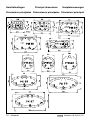
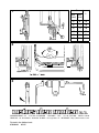
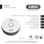
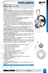
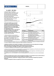
Bedieningshandleiding en
installatieinstructies
2
Operation manual and
installation instructions
4
Bedienungshandbuch und
Einbauanleitung
6
Manuel d’utilisation et
instructions d’installation
8
Manual de manejo y
instrucciones de instalación
10
Manuale per l’uso e
istruzioni per l’installazione
12
Patrijspoorten
Portholes
Bullaugen
Hublots
Portillos
Oblò
PM
PW
PX
PZ
C o p y r i g h t © 2 0 0 5 Ve t u s d e n O u d e n n . v. S c h i e d a m H o l l a n d
Inleiding
Deze handleiding geldt voor de Vetus patrijspoorten type:
- PM
(PM21, PM22, PM23, PM24 en PM25)
- PW
(PW30, PW31 en PW32)
- PX
(PX55, PX56 en PX57)
- PZ
(PZ71, PZ72, PZ73, PZ74, PZ75, PZ76 en PZ77)
Voor tekeningen zie pag. 14, 15 en 16.
Veiligheid
Waarschuwing: Houdt patrijspoorten tijdens de vaart van een schip gesloten.
Montage algemeen
N.B.: Op elke patrijspoort is de hoogst toegestane ontwerpcategorie en het hoogst toegestane toepassingsgebied vermeld.
Houdt met de montage van de patrijspoort met het volgende rekening:
- Een patrijspoort moet naar binnen openen.
- Indien toegepast in gebied 1 op zeil- of motorvaartuigen naar ontwerp categorie A of B
mag geen enkel deel van de patrijspoort uitsteken buiten de romp.
- Uitsluitend monteren in een volkomen vlakke wand! In een gekromde wand zal de
patrijspoort, in gesloten toestand, niet waterdicht zijn!
Waarschuwing
Stof dat vrijkomt bij het bewerken van glasvezel versterkt polyester is schadelijk voor
longen en ogen. Draag daarom tijdens het bewerken altijd een stofkapje en een stofbril. Ventileer de ruimte goed.
Onderhoud algemeen
Reinig de geanodiseerde of poeder-gecoate aluminium profielen regelmatig; afhankelijk
van de mate van verontreiniging 2 à 4 maal per jaar.
Gebruik uitsluitend neutrale, niet krassende, reinigingsmiddelen. Gebruik GEEN alkalische, zure en/of krassende middelen.
Bescherm de afdichtingsrubbers met talkpoeder.
2
070204.01
Patrijspoorten PM, PW, PX, PZ
NEDERLANDS
Bediening
Openen:
Draai de knevels een kwart slag linksom en trek aan de knevels om het venster te openen. Het venster blijft door het klikscharnier vanzelf in iedere gewenste stand open
staan.
Sluiten:
Zorg er voor dat de knevels in stand ‘open’ staan. Druk het venster dicht en draai de
knevels een kwart slag rechtsom.
Montage
De patrijspoort kan worden ingebouwd in een wand met een dikte van minimaal 3 mm en
maximaal 22 mm.
Teken het te maken gat af met behulp van het frame van de patrijspoort, voor hoofdafmetingen zie pag. 14, 15.
Maak het gat in de opbouw d.m.v. zagen -bij polyester, aluminium of hout- of d.m.v. snijbranden -bij staal-.
Braam het gat goed af en breek de kanten.
Deze patrijspoorten hebben een klemprofiel; bevestigingsgaten in de wand van het schip
zijn NIET nodig.
Breng een rups kit aan om een goede afdichting te verkrijgen; zie tekening 1, (1) = kit.
Plaats de poort in het gat.
Bevestigingsschroeven:
Pas plaatschroeven 4,2 mm AB (Nr. 8 AB) volgens ISO/R 1483 toe. Kies een schroeflengte afhankelijk van de wanddikte, zie de tabel bij tekening 1. D = klembereik, L =
schroeflengte, *= 32 mm schroef inkorten tot 30 mm.
Monteer de schroeven en zet deze goed vast.
Stel de knevel na montage in om de patrijspoort goed te laten sluiten, zie Onderhoud,
‘nastellen knevel’.
Onderhoud
Nastellen knevels:
Stel de knevels na als de patrijspoort niet meer goed sluit, zie tekening 2.
Nastellen scharnieren:
Stel de scharnieren na als het deksel niet meer geopend blijft staan, zie tekening 3.
Technische gegevens
Frame, tegenrand : Aluminium (AlMgSi 0.5)
Venster
: PMMA 10 mm
Patrijspoorten PM, PW, PX, PZ
070204.01
3
Introduction
This Manual applies to the following Vetus porthole types:
- PM
(PM21, PM22, PM23, PM24 and PM25)
- PW
(PW30, PW31 and PW32)
- PX
(PX55, PX56 and PX57)
- PZ
(PZ71, PZ72, PZ73, PZ74, PZ75, PZ76 and PZ77)
See pages 14, 15 and 16 for Drawings.
Safety
Warning: Always keep portholes closed when under way.
Fitting, general
N.B.: The highest permitted design category and the highest permitted application is stated on every porthole.
When fitting the porthole, take the following into account:
- A porthole must always open inward.
- When fitted in area 1 on sailing or motor ships within design category A or B, no part of
the porthole should protrude beyond the hull.
- Only fit in a completely flat hull section! The porthole will never be watertight when
closed if fitted in a curved surface!
Warning
Dust released when cutting and sanding glass-fibre reinforced polyester is hazardous to lungs and eyes. So always wear a dust mask and goggles when working
with this material. Ventilate the working area well.
Maintenance, general
Clean anodized or powder-coated aluminium profiles regularly; 2 to 4 times a year,
depending on how dirty they get.
Use only neutral cleaning agents. NEVER use alkaline, acid and/or abrasive cleaners.
Protect the sealing rubbers with talcum powder.
4
070204.01
Portholes PM, PW, PX, PZ
ENGLISH
Operating
Opening:
Turn the clamps a quarter turn to the left and pull on the clamps to open the window.
The window will remain open in any position due to the click hinge.
Closing:
Ensure that the clamps are in the ‘open’ position. Push the window closed and turn the
clamps a quarter turn to the right.
Fitting
The porthole can be fitted in a surface with a minimum thickness of 3 mm. and a maximum
thickness of 22 mm.
Draw the hole to be cut out using the porthole frame, for the main dimensions, see page
14, 15.
Cut the hole in the ship by sawing in polyester, aluminium or wood, or by acetylene cutting
for steel.
Remove all burrs carefully and smooth the edges.
These portholes have a clamp profile; fixing holes in the side of the ship are NOT necessary.
Apply a sufficient amount of sealant to ensure a good seal, see Drawing 1, (1) = Sealant.
Position the hatch in the hole.
Fixing Screws:
Use 4.2 mm. AB (No: 8 AB) recess head screws in accordance with ISO/R 1483. Choose
a screw length related to the wall thickness, see Table in Drawing 1. D= Clamp Reach,
L= Screw Length, *Shorten 32 mm. screw to 30 mm.
Fit screws and tighten securely.
Adjust the clamps after fitting to allow the porthole to close properly. See Maintenance, ‘readjusting clamps’.
Maintenance
Re-adjusting clamps:
Re-adjust the clamps when the porthole no longer closes properly. See Drawing 2.
Re-adjusting hinges:
Re-adjust the hinges when the porthole no longer remains open. See Drawing 3.
Technical Data
Frame, backplate
Window
: Aluminium (AlMgSi0.5)
: PMMA 10 mm
Portholes PM, PW, PX, PZ
070204.01
5
Einleitung
Diese Anleitung gilt für die Vetus-Bullaugen vom Typ:
- PM
(PM21, PM22, PM23, PM24 und PM25).
- PW
(PW30, PW31 und PW32).
- PX
(PX55, PW56 und PQ 57).
- PZ
(PZ71, PZ72, PZ73, PZ74, PZ75 und PZ76).
Abbildungen siehe Seite 14, 15 und 16.
Sicherheit
Warnhinweis: Halten Sie alle Bullaugen währen der Fahrt geschlossen.
Einbau, allgemein
Hinweis: Auf jedem Bullauge ist die höchstzulässige Entwurfskategorie und das
höchstzulässige Anwendungsgebiet angegeben.
Berücksichtigen Sie beim Einbau eines Luks folgendes:
- Ein Bullauge muß sich nach innen öffnen lassen.
- In Gebiet 1 darf auf Segel- und Motoryachten nach Entwurfskategorie A oder B kein Teil
eines Bullauges über den Rumpf hinausragen.
- Bauen Sie ein Bullauge in eine vollkommen ebene Fläche ein! In einer gekrümmten
Fläche wird das Bullauge in geschlossenem Zustand niemals wasserdicht sein!
Warnhinweis
Der bei der Bearbeitung von glasfaserverstärktem Kunststoff freigesetzte Staub
schadet den Lungen und Augen. Tragen Sie darum bei dieser Arbeit immer eine
Staubmaske und eine Sicherheitsbrille. Sorgen Sie für ausreichende Lüftung des
Arbeitsraumes.
Wartung, allgemein
Reinigen Sie die anodisierten und pulverbeschichteten Aluminiumprofile regelmäßig: je
nach Verschmutzungsrad 2 bis 4 Mal jährlich.
Verwenden Sie ausschließlich neutrale Reinigungsmittel und keine alkalischen, sauren
und/oder schleifenden Mittel.
Schützen Sie die Dichtungsgummis mit Talkumpuder.
6
070204.01
Bullaugen PM, PW, PX, PZ
DEUTSCH
Bedienung
Öffnen:
Drehen Sie die Vorreiber eine Viertelumdrehung links herum und ziehen Sie das Fenster
an den Vorreibern auf. Das Fenster bleibt durch die Einrastscharniere in jeder
gewünschten Stellung offen stehen.
Schließen:
Vor dem Schließen müssen alle Vorreiber in der Stellung ‘offen’ stehen. Drücken Sie das
Fenster zu und drehen Sie die Vorreiber eine Viertelumdrehung rechts herum.
Einbau
Die Bullaugen können in Wände von 3 mm bis 22 mm Dicke eingebaut werden.
Zeichnen Sie die herzustellende Öffnung mit Hilfe des Bullaugenrahmens an;
Hauptabmessungen siehe Seite 14, 15.
In Polyester, Aluminium und Holz wird die erforderliche Öffnung gesägt.
Bei Stahl wird ein Schneidbrenner benutzt.
Entgraten und fasen Sie die Ränder.
Die Bullaugen werden nicht mit Schrauben, sondern mit Klemmvorrichtungen befestigt.
Bohren ist nicht notwendig.
Bringen Sie für eine einwandfreie Dichtung einen Streifen Dichtungsmasse an. Siehe
Abbildung 1, (1) = Dichtungsmasse.
Bringen Sie das Bullauge an der Öffnung an.
Befestigungsschrauben:
Verwenden Sie Blechschrauben 4,2 mm AB (Nr. 8 AB) gemäß ISO/R 1483. Die
Schraubenlänge hängt von der Wandstärke ab, siehe Tabelle bei Zeichnung 1. D =
Klemmbereich, L = Schraubenlänge, * = 32 mm lange Schraube auf 30 mm verkürzen.
Bringen Sie die Schrauben an und drehen Sie diese fest.
Stellen Sie nach dem Einbau die Vorreiber so ein, daß sich das Bullauge einwandfrei
öffnen und schließen läßt, siehe ‘Wartung: Nachstellen der Vorreiber’.
Wartung
Nachstellen der Vorreiber:
Wenn sich das Bullauge nicht mehr ordnungsgemäß schließen läßt, müssen die
Vorreiber nachgestellt werden, siehe Abbildung 2.
Nachstellen der Scharniere:
Wenn das Fenster nicht mehr von selbst offen stehenbleibt, können Sie die Scharniere
nachstellen, siehe Abbildung 3.
Technische Daten
Rahmen, Außenrand : Aluminiumlegierung (AlMgSi 0,5)
Fenster
: PMMA 10 mm
Bullaugen PM, PW, PX, PZ
070204.01
7
Introduction
Cette notice concerne les types de hublots Vetus suivants :
- PM
(PM21, PM22, PM23, PM24 et PM25).
- PW
(PW30, PW31 et PW32).
- PX
(PX55, PX56 et PX57).
- PZ
(PZ71, PZ72, PZ73, PZ74, PZ75, PZ76 et PZ77).
Figures, voir pages 14, 15 et 16.
Sécurité
Avertissement : Maintenir les hublots fermés pendant la navigation.
Montage, généralités
N.B. : La plus haute catégorie de conception ainsi que le plus haut domaine d’application
autorisés sont indiqués sur chaque hublot.
Lors du montage du hublot, veuillez tenir compte des indications suivantes :
- Un hublot doit s’ouvrir vers l’intérieur.
- Si le hublot est monté dans le domaine 1 sur des bateaux à voile ou à moteur selon une
conception de catégorie A au B, aucun élément du hublot ne devra dépasser de la
coque.
- Monter le hublot uniquement sur une paroi absolument plate! Si la paroi est incurvée,
le capot ne sera pas étanche en position fermée !
Avertissement
La poussière libérée par le traitement du polyester renforcé fibre de verre est nocive
pour les poumons et les yeux. On portera donc toujours un masque antipoussière et
des lunettes de protection. Bien aérer le local de travail.
Entretien, généralités
Nettoyer régulièrement les profilés en aluminium anodisé ou revêtu par poudrage, 2 à 4
fois par an selon le degré de saleté.
Utiliser uniquement des produits de nettoyage neutres, non abrasifs. Ne PAS utiliser de
produits alcalins, acides et/ou abrasifs.
Protéger les caoutchoucs d’étanchéité avec du talc.
8
070204.01
Hublots PM, PW, PX, PZ
FRANÇAIS
Commande
Ouverture :
Tourner les attaches d’un quart de tour à gauche et tirer sur les attaches pour ouvrir la
fenêtre. La charnière à déclic maintient la fenêtre dans la position souhaitée.
Fermeture :
Veiller à ce que les attaches soient en position ‘ouverte’. Fermer la fenêtre en la poussant, tourner les attaches d’un quart de tour à droite.
Montage
Le hublot peut être monté dans une paroi ayant une épaisseur de 3 mm au minimum et
de 22 mm au maximum.
Dessiner l’ouverture à réaliser à l’aide du cadre de hublot, dimensions principales voir figure 14, 15.
Découper l’ouverture avec une scie pour les constructions en polyester, aluminium ou
bois, ou au chalumeau pour les constructions en acier.
Ebarber soigneusement l’ouverture et briser les bords.
Ces hublots ont un profilé de serrage; il n’est PAS nécessaire de faire des trous de fixation
dans la paroi du bateau.
Déposer un cordon de mastic pour assurer une bonne étanchéité, voir figure 1, (1) = mastic.
Positionner le hublot dans l’ouverture.
Vis d’assemblage :
Utiliser des vis à auto-taraudage 4,2 mm AB (No. 8 AB) selon ISO/R 1483. Choisir une
longueur de vis en fonction de l’épaisseur de la paroi, voir tableau figure 1. D = portée
de serrage, L = longueur de vis, * = 32 mm raccourcir les vis à 30 mm.
Monter les vis et bien les serrer.
Après le montage, régler les attaches pour assurer une bonne fermeture du hublot, voir
Entretien, ‘réglage postérieur des attaches’.
Entretien
Réglage postérieur des attaches:
Régler les attaches si le hublot ne ferme plus parfaitement, voir figure 2.
Réglage postérieur des charnières:
Régler les charnières si le couvercle ne reste plus en position ouverte, voir figure 3.
Fiche technique
Cadre, contre-bord : Aluminium (AlMgSiO.5)
Fenêtre
: PMMA 10 mm
Hublots PM, PW, PX, PZ
070204.01
9
Introducción
El
-
presente manual sirve para las portillas Vetus, tipo:
PM
(PM21, PM22, PM23, PM24 y PM25).
PW
(PW30, PW31 y PW32).
PX
(PX55, PX56 y PX57).
PZ
(PZ71, PZ72, PZ73, PZ74, PZ75, PZ76 y PZ77).
Para dibujos verse páginas 14, 15 y 16.
Seguridad
Advertencia: Procure que las portillas estén cerradas durante la navegación del barco.
Montaje generalidades
N.B.: En cada portilla se indica la máxima categoría de diseño admitida, así como la máxima área de aplicación admitida.
Al montar la portilla téngase en cuenta lo siguiente:
- Una portilla debe abrir hacia dentro.
- En caso de aplicación en la zona 1 de motonaves o veleros según categoría de diseño
A o B, ninguna parte de la portilla debe sobresalir del casco.
- ¡Monte la portilla en una pared completamente plana! En una pared curvada, la portilla, en posición cerrada, ¡no está a prueba de agua!
Advertencia
El polvo que se desprende al tratar poliéster reforzado con fibra de vidrio es perjudicial para los pulmones y ojos. Por lo tanto, siempre tápese la boca y póngase
gafas de protección durante el trabajo. Ventile bien el espacio.
Mantenimiento generalidades
Limpie a intervalos regulares los perfiles de aluminio anodizados o los perfiles con revestimiento de polvo; 2 a 4 veces al año, dependientemente del grado de suciedad.
Sólo use detergentes neutrales, no abrasivos. NO use substancias alcálicas, ácidas y/o
abrasivas.
Proteja las gomas de estanqueidad con polvos de talco.
10
070204.01
Portillas PM, PW, PX, PZ
ESPAÑOL
Operación
Abrir:
Gire los cerrojos noventa grados hacia la izquierda y tire de los cerrojos para abrir la
ventana. Por las bisagras de trinquete, la ventana permanece abierta en cualquier posición deseada.
Cerrar:
Procure que los cerrojos estén en posición ‘abierta’. Cierre la ventana y gire los cerrojos noventa grados hacia la derecha.
Montaje
La portilla puede empotrarse en una pared de 3 mm de espesor como mínimo y de 22 mm
como máximo.
Marque el hueco a serrar, con la ayuda del bastidor de la portilla; para dimensiones principales, verse pág. 14, 15.
Haga el hueco en la estructura, serrándolo en caso de poliéster, aluminio o madera- o cortándolo con soplete - en caso de acero-.
Desbarbe el hueco y corte los bordes.
Estas portillas van provistas de un perfil autosujeción; NO hace falta taladrar agujeros de
fijación en la pared del barco.
Aplique una oruga de pegamento para conseguir un buen cierre, verse dibujo 1, (1) =
pegamento.
Coloque la portilla en el hueco.
Tornillos de fijación:
Use tornillos de chapa 4,2 mm AB (No. 8 AB), conforme a ISO/R 1483. Elija un largo de
tornillo dependientemente del espesor de la pared; verse la tabla al lado del dibujo 1.
D = alcance de sujeción, L = largo de tornillo, * = recortar tornillo de 32 mm a 30 mm.
Introduzca los tornillos y apriételos bien.
Reajuste el cerrojo después del montaje, para que la portilla cierre bien; verse
Mantenimiento, ‘reajustar cerrojo’.
Mantenimiento
Reajustar los cerrojos:
Reajuste los cerrojos cuando la portilla ya no cierre bien, verse dibujo 2.
Reajustar las bisagras:
Reajuste las bisagras cuando la portilla ya no se permanezca abierta, verse dibujo 3.
Datos técnicos
Bastidor, contraborde : Aluminio (AIMgSiO.5)
Ventana
: PMMA 10 mm
Portillas PM, PW, PX, PZ
070204.01
11
Introduzione
Il
-
presente manuale si applica ai seguenti tipi di oblò Vetus:
PM
(PM21, PM22, PM23, PM24 e PM25)
PW
(PW30, PW31 e PW32)
PX
(PX55, PX56 e PX57)
PZ
(PZ71, PZ72, PZ73, PZ74, PZ75, PZ76 e PZ77)
Per i disegni vedi pag. 14, 15 e 16.
Sicurezza
Attenzione: Tenere chiusi gli oblò durante la navigazione.
Montaggio generalità
N.B.: Su ogni oblò è riportata la massima categoria e il massimo campo di applicazione
ammessi.
Al momento di montare l’oblò tenere presente quanto segue:
- Ogni oblò si deve aprire verso l’interno.
- Se applicato nel campo 1 su imbarcazioni a vela o a motore in base alla categoria A o
B, nessuna componente dell’oblò può sporgere dalla carena.
- Montare l’oblò su una parete del tutto dritta. Se la parete è curva, l’oblò da chiuso non
sarà impermeabile.
Attenzione
La polvere liberata dalla lavorazione del poliestere rinforzato con fibra di vetro è tossica per i polmoni e gli occhi. Durante queste operazioni indossare sempre la
mascherina e gli occhialini protettivi. Ventilare bene l’ambiente.
Manutenzione generalità
Pulire regolarmente i profili in alluminio anodizzato o verniciato; a seconda del livello di
sporcizia 2-4 volte all’anno.
Utilizzare esclusivamente detergenti neutri. NON utilizzare prodotti alcalini, acidi e/o abrasivi.
Proteggere i gommini impermeabili con borotalco.
12
070204.01
Oblò PM, PW, PX, PZ
ITALIANO
Funzionamento
Apertura:
Ruotare le serrature un quarto di giro in senso antiorario e tirare le serrature per aprire
l’oblò. La finestra rimane automaticamente aperta nella posizione desiderata grazie alla
serratura con fermo.
Chiusura:
Sincerarsi che le serrature siano in posizione ‘aperto’. Chiudere l’oblò spingendolo e
ruotare le serrature di un quarto di giro in senso orario.
Montaggio
L’oblò si può montare in una parete dallo spessore un minimo di 3 mm e massimo di 22
mm.
Utilizzando il telaio dell’oblò demarcare il punto in cui praticare il foro, per le dimensioni
principali vedi pagina 14, 15.
Praticare il foro nella struttura segando - se la struttura è di poliestere, di alluminio o di
legno, e con ossitaglio alla fiamma se invece è di acciaio.
Ripulire bene il foro ed eliminare gli spigoli.
Questi oblò hanno un profilo dotato di fermo; NON sono necessari fori di fissaggio nella
parete dell’imbarcazione.
Applicare una sostanza sigillante per garantire una buona impermeabilizzazione, vedi disegno 1, (1) = silicone
Collocare l’oblò nel foro.
Viti di fissaggio:
Utilizzare viti di 4,2 mm AN (N. 8 AB) in base a ISO/R 1483. Scegliere la lunghezza delle
viti a seconda dello spessore della parete, vedi la tabella al disegno 1. D = portata del
fermo, L = lunghezza della vite, * = ridurre la vite da 32 mm a 30 mm.
Montare le viti e avvitarle fermamente.
Dopo il montaggio regolare le serrature perché l’oblò si chiuda bene, vedi Manutenzione,
‘regolazione delle serrature’.
Manutenzione
Regolazione delle serrature:
Fissare le serrature quando l’oblò non si chiude più bene, vedi disegno 2.
Regolazione delle cerniere:
Fissare le cerniere quando il boccaporto non rimane più aperto, vedi disegno 3.
Dati tecnici
Telaio, bordo : Alluminio (AlMgSi0,5)
Finestrino
: PMMA 10 mm
Oblò PM, PW, PX, PZ
070204.01
13
Hoofdafmetingen
Principal dimensions
Hauptabmessungen
Dimensions principales Dimensiones principales Dimensioni principali
14
070204.01
Portholes PM, PW, PX, PZ
Hoofdafmetingen
Principal dimensions
Hauptabmessungen
Dimensions principales Dimensiones principales Dimensioni principali
De bij de streeplijnen aangegeven afmetingen zijn de inbouwmaten.
The measurements indicated by a dotted line are the building-in sizes
Die bei den gestrichelten Linien angegebenen Maßangaben sind die Einbaumaße.
Les dimensions indiquées pour les lignes pointillées sont les cotes de montage.
Las dimensiones indicadas por línea interrumpida son las dimensiones de empotramiento.
Le misure indicate vicino alle linee tratteggiate sono le misure di montaggio.
Portholes PM, PW, PX, PZ
070204.01
15
D
1
min. max.
(mm) (mm)
L
3
8
13
6
11
16
9
14
19
12
17
22
15
20
25
20
22
30*
2
3
FOKKERSTRAAT 571 - 3125 BD SCHIEDAM - HOLLAND - TEL.: +31 10 4377700 - TELEX: 23470
TELEFAX: +31 10 4372673 - 4621286 - E-MAIL: [email protected] - INTERNET: http://www.vetus.com
Printed in the Netherlands
070204.01 05-05