1
PREPARATION
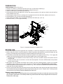
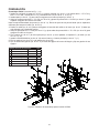
47050C Assembly (refer to Fig. 1 & 3)
1.Attach leg assemblies (ref. no. 2) to main frame (ref. no. 1) using M12x1.75x70L & M12x1.75x120L bolts,
M12x1.75 nuts & M12x3t washers (ref. nos. 3, 15, 4 & 5).
2.Install caps (ref. no. 17) to cover the holes on the main frame (ref. no. 1).
3.Loosen all four of the M12x1.75x70L bolts (ref. no. 8) and tighten the M10x1.5x60L bolts (ref. no. 11) to expand
the roller insert hole.
Note: Do not overtighten the bolts (ref. no. 11). Adjust bolt’s tightness until it is expanded enough for accepting the
roller (ref. no. 6).
4.Slide roller (ref. no. 6) into the roller insert hole on frame (ref. no. 7) until it is aligned with the edge of the hole.
5. Loosen the M10x1.5x60L bolts (ref. no. 11) and tighten all the M12x1.75x70L bolts (ref. no. 8) to secure the roller
onto the frame.
6.Attach the frame (ref. no 7) to main frame (ref. no. 1) using the pin, c-clip and roller. (ref. no. 12, 13 & 14).
7.Install hydraulic unit (ref. no. 18) in between the frame and main frame (ref. no. 7 & 1).
8.Attach hooks (ref. no. 21) to chain (ref. no. 20).
9.Attach one end of hook (ref. no. 21) through angle frame hole and attach another hook to the other hole.
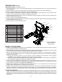
Size of Hardware Kits
Qty
3 bolt
M12x70
4
4 lock washer M12
6
5 nut
M12
6
8 bolt
M12x70
4
9 lock washer M12
4
10 nut
M12
4
11 bolt
M10x60
2
15 bolt
M12x120 4
Figure 3 - Assembly Illustration for Model 47050C
3