1
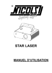
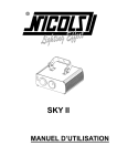
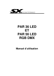
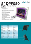
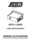
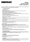
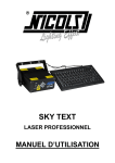
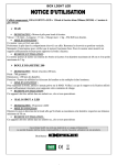
CENTOR LASER LASER PROFESSIONNEL MANUEL D’UTILISATION Nous vous recommandons de lire attentivement le manuel avant toute utilisation. 1. RECOMMANDATIONS GENERALES a. DEBALLAGE DE L’APPAREIL Nous vous remercions pour l’achat de cet appareil. Lire attentivement les consignes ci-après. Elles contiennent des informations importantes sur la sécurité de l'installation ainsi que sur l'utilisation et la maintenance de l'équipement. Il est primordial que l’utilisateur suive les instructions de sécurité et avertissements inclus dans ce manuel. Le vendeur ne prend pas en charge la responsabilité des défauts ou de tout problème résultant du fait de n’avoir pas tenu compte des mises en garde ce manuel. Conservez le présent manuel avec l'équipement pour référence ultérieure. En cas de vente de l'équipement à un autre utilisateur, il est important que le présent manuel soit joint à l'équipement afin que le nouvel utilisateur dispose des informations nécessaires à son utilisation et puisse prendre connaissance des mises en gardes relatives à la sécurité. Ce produit est approprié pour créer des programmes et des effets lasers de haute qualité. Cet appareil a été conçu pour la production d’effets de lumière décoratifs et est utilisé uniquement dans les spectacles lumineux. Ce produit est un appareil qu’on appelle laser de spectacle émettant des rayonnements laser. Veuillez-vous référez au paragraphe suivant sur les instructions de sécurité laser. Avant tout première utilisation, déballez le set et vérifiez qu’il n’y ait pas eu de dommages pendant le transport. Vérifiez qu’il ne manque aucune partie fournie avec l’appareil : -1 x CENTOR LASER -1 x CORDON D’ALIMENTATION -1 x NOTICE b. INTRUCTIONS DE SECURITE Il est important de relier l’appareil à la terre afin d’éviter tout choc électrique. Avant tout première utilisation, assurez-vous que l’alimentation soit compatible à la tension locale. Afin de réduire tout risque d’électrocution, ne jamais ouvrir le boitier de l’appareil. Cet appareil n’est conçu que pour une utilisation en intérieur uniquement. Ne pas exposer l’appareil à la pluie ou à l’humidité. La température ambiante pour le fonctionnement de l’appareil est de 18 à 30°C. Ne pas dépasser cette température 1- Ne pas allumer puis éteindre et rallumer l’appareil de façon répétée afin de ne pas réduire la durée de vie de l’appareil. Ne pas faire fonctionner l’appareil en continu pendant plus de 4 heures pour ne pas réduire la durée de vie de l’appareil. Si vous n’utilisez pas l’appareil pendant une longue période, débranchez l’appareil. Pour des besoins de maintenance ou des réparations, débranchez l’appareil. Ne pas insérer d’objets métalliques ou verser du liquide sur/dans l’appareil. Si cela se produisait, éteignez immédiatement l’appareil et débranchez-le du secteur. Ne pas placer l’appareil près de sources de chaleur. Placez l’appareil dans un endroit bien ventilé et à 50 cm minimum des murs. Ne pas couvrir les orifices de ventilations pour éviter tout risque de surchauffe. Ne pas utiliser dans un endroit poussiéreux. Utilisez des chiffons doux pour enlever la poussière sur la lentille externe de l’appareil pour optimiser le rendu lumineux. Nettoyez l’appareil régulièrement. Ne pas laisser l’appareil à la portée des enfants ou des personnes non qualifiées. Pendant le montage de l’appareil, ne pas laisser des personnes non concernées participer au montage ou à la maintenance. Les installations doivent être faites par du personnel qualifié et conformément aux réglementations en vigueur. Ne jamais retirer les étiquettes collées sur l’appareil. Il est interdit d’apporter des modifications à l’appareil pour des raisons de sécurité. Si des parties de l’appareil sont endommagées (cordons, prises, lentilles, boitiers, lyres de fixation), ne pas faire fonctionner l’appareil et contacter cotre revendeur. L’appareil ne contient pas de pièces que puissiez remplacer par vous-mêmes. Contactez votre revendeur. Toujours utiliser des pièces de même type. Ne jamais court-circuiter ou réparer un fusible. Utilisez l’emballage d’origine pour le transport de l’appareil. Ne jamais regarder directement ou fixer la source de lumière. Ne pas utiliser d’effets en présence de personnes souffrant d’épilepsie. c. INTRUCTIONS DE SECURITE LASER Selon la réglementation en vigueur EN/IEC 60825-1, ce laser fait partie de la classe 4. Une exposition directe des yeux au faisceau peut être dangereux 2- DANGER : RAYONNEMENT LASER APPAREIL DE CLASSE 4 NE PAS REGARDER DIRECTEMENT LE FAISCEAU LUMINEUX : LES RAYONNEMENTS LASER PEUVENT ENDOMMAGER LES YEUX ET LA PEAU. EVITER L’EXPOSTION AU LASER TOUTES LES MESURES DE PROTECTION DOIVENT ETRE APPLIQUEES POUR DES RAISONS DE SECURITE Ce produit est ce qu’on appelle un laser de spectacle émettant des rayonnements avec un spectre de longueurs d’onde. Le laser (amplification de lumière par émission stimulée de rayonnement) est un dispositif susceptible de produire ou d’amplifier les rayonnements électromagnétiques de longueur d’onde correspondant aux rayonnements optiques essentiellement par le procédé de l’émission stimulée contrôlée. Outre les effets secondaires qui sont dus aux conditions de fonctionnement et aux risques d’incendie et de brûlures, le danger essentiel causé par ces dispositifs provient de l’illumination. Les effets sur l’œil sont fonction des caractéristiques du laser, de la distance de ce dernier à l’œil et de facteurs liés aux propriétés des différents milieux de l’œil. Ce danger est considérablement accru si le rayonnement est concentré sur une toute petite surface, c’est pourquoi les effets sur l’œil constituent les risques les plus importants liés aux utilisations des lasers. La classe 3B est susceptible d’être dangereuse dans certaines conditions La classe 4 requiert des précautions rigoureuses. INSTALLATION DE L’APPAREIL Les appareils de classe 3 et 4 utilisables exclusivement en plein air, sont mis en œuvre par un technicien compétent et formé aux risques spécifiques des lasers et accompagnés d’une notice. La zone dite « zone réservée au public » est définir par l’espace situé jusqu’à 3 mètres au dessus de la surface occupée par le public et sur une bande de 2.5 mètres autour de cette dernière. La zone réservée est matérialisée au sol. Dans cette zone, aucun « tir laser » (rayonnement fixe, rectiligne) n’est admis en direction du public, quelle que soit la classe du laser, sauf si un périmètre d’exclusion du public de 4 mètres de rayon, matérialisé, et mis en place. Seul est admis un rayonnement par balayage (rayonnement en permanence en mouvement) dans cette zone. UTILISATION L’appareil à laser est hors de portée du public au minimum : 3- - A 3 mètres au dessus du sol accessible au public ou - Protégé par un périmètre de sécurité de 5 mètres de rayon. -L’exploitant s’assure que les appareils de classe 3B et 4 est mis en œuvre par un technicien compétent et formé aux risques spécifiques des lasers, qui est présent pendant tout la durée de l’animation et est en mesure de l’arrêter immédiatement. Lors de l’installation ou de réglages, le technicien portera des lunettes de protection. Nous vous recommandons de bien vous rappelez des points suivants. - La lumière diffuée par les lasers est différente de tout autre type de source lumineuse qui vous est familier - La lumière diffusée par un tel produit peut éventuellement causer des dommages aux yeux si elle n’est pas réglée et utilisée de manière adéquate. - La lumière d’un rayon laser est des milliers de fois plus concentrée que la lumière produite par n’importe quelle autre source de lumière. Cette concentration peut causer des dommages irréversibles et instantanés aux yeux, en brûlant la rétine. Même si vous ne ressentez aucune impression de chaleur venant d’un rayon laser, il est capable de blesser, voire de rendre aveugle son utilisateur et/ou public. Ne JAMAIS donc regarder l’orifice d’où provient le rayon laser ou le rayon lui-même. - Ne dirigez jamais le faisceau laser directement sur des personnes. - Ne jamais laissez l’appareil fonctionner l’appareil sans surveillance. EXPELEC ne peut en aucun cas être tenu comme responsable aux dommages causés par des installations incorrectes et/ou par du personnel non qualifié. 2. SPECIFICATIONS TECHNIQUES Alimentation : 230V/50hz Longueur : Vert 532 nm / 10 x 100 mW Rouge 650 nm / 200 mW Bleu 450 nm / 400 mW Dimensions : 295 mm de haut et 750 mm de diamètre Poids : 14 kg LIVRE EN FLIGHT CASE 4- 3. CARACTERISTIQUES FACE AVANT et FACE ARRIERE 2 1. MICRO 2. Ouverture laser 3. Prise alimentation 4. Tableau explicatif pour le réglage des dipswitches 5. Bouton pour la sensibilité du son 6. Dipswitches pour le réglage des fonctions 7. Commutateur ON/OFF 8. Connexion DMX 9. Oeillet pour élingue de sécurité 5- 4. FONCTIONS L’appareil est équipé du mode musical, mode auto et DMX. En mode DMX512, le mode musical, auto et DMX (sous menu) sont optionnels. Dans le sous menu DMX, le réglage des moteurs permet de contrôler l’orientation des faisceaux. De plus, le contrôle simultané de tous les moteurs permet de régler la position de tous les faisceaux. Paramètres contrôle DMX Canaux CH 1 CH 2 Fonction Valeur Description 10-49 Invalid 50-99 DMX sub-mode 100-149 Sound active mode 150-255 Auto mode 0-19 Red & blue work as procedures scheduled mode 20-59 Red & blue laser OFF 60-99 Blue laser ON 100-149 Red laser ON 150-255 Red & blue laser ON Mode Sound active or Auto mode Chaque moteur pour régler les angles des faisceaux verts est contrôlable manuellement sous les canaux qui suivent QUAND le canal 1 est dans le sous menu DMX (50-99). CH 3 0-9 Motor 1, angle=0, corresponding laser OFF 10-19 Motor 1, angle=7.2 , corresponding laser ON 20-39 Motor 1, angle=14.4 , corresponding laser ON 40-59 Motor 1, angle=21.6 , corresponding laser ON 60-79 Motor 1, angle=28.8, corresponding laser ON 80-99 Motor 1, angle=36 , corresponding laser ON Rotating angle 6- CH 4 CH 5 100-119 Motor 1, angle=43.2 , corresponding laser ON 120-139 Motor 1, angle=50.4 , corresponding laser ON 140-159 Motor 1, angle=57.6 , corresponding laser ON 160-179 Motor 1, angle=64.8 , corresponding laser ON 180-199 Motor 1, angle=72 , corresponding laser ON 200-219 Motor 1, angle=79.2, corresponding laser ON 220-239 Motor 1, angle=86.4 , corresponding laser ON 240-255 Motor 1, angle=93.6 , corresponding laser ON 0-9 Motor 2, 10-19 Motor 2, angle=7.2 , corresponding laser ON 20-39 Motor 2, angle=14.4 , corresponding laser ON 40-59 Motor 2, angle=21.6 , corresponding laser ON 60-79 Motor 2, angle=28.8, corresponding laser ON 80-99 Motor 2, angle=36 , corresponding laser ON 100-119 Motor 2, angle=43.2 , corresponding laser ON 120-139 Motor 2, angle=50.4 , corresponding laser ON 140-159 Motor 2, angle=57.6 , corresponding laser ON 160-179 Motor 2, angle=64.8 , corresponding laser ON 180-199 Motor 2, angle=72 , corresponding laser ON 200-219 Motor 2, angle=79.2, corresponding laser ON 220-239 Motor 2, angle=86.4 , corresponding laser ON 240-255 Motor 2, angle=93.6 , corresponding laser ON 0-9 Motor 3, 10-19 Motor 3, angle=7.2 , corresponding laser ON 20-39 Motor 3, angle=14.4 , corresponding laser ON 40-59 Motor 3, angle=21.6 , corresponding laser ON 60-79 Motor 3, angle=28.8, corresponding laser ON 80-99 Motor 3, angle=36 , corresponding laser ON 100-119 Motor 3, angle=43.2 , corresponding laser ON 120-139 Motor 3, angle=50.4 , corresponding laser ON 140-159 Motor 3, angle=57.6 , corresponding laser ON 160-179 Motor 3, angle=64.8 , corresponding laser ON 180-199 Motor 3, angle=72 , corresponding laser ON angle=0, corresponding laser OFF Rotating angle Rotating angle 7- angle=0, corresponding laser OFF CH 6 CH 7 CH 8 200-219 Motor 3, angle=79.2, corresponding laser ON 220-239 Motor 3, angle=86.4 , corresponding laser ON 240-255 Motor 3, angle=93.6 , corresponding laser ON 0-9 Motor 4, 10-19 Motor 4, angle=7.2 , corresponding laser ON 20-39 Motor 4, angle=14.4 , corresponding laser ON 40-59 Motor 4, angle=21.6 , corresponding laser ON 60-79 Motor 4, angle=28.8, corresponding laser ON 80-99 Motor 4, angle=36 , corresponding laser ON 100-119 Motor 4, angle=43.2 , corresponding laser ON 120-139 Motor 4, angle=50.4 , corresponding laser ON 140-159 Motor 4, angle=57.6 , corresponding laser ON 160-179 Motor 4, angle=64.8 , corresponding laser ON 180-199 Motor 4, angle=72 , corresponding laser ON 200-219 Motor 4, angle=79.2, corresponding laser ON 220-239 Motor 4, angle=86.4 , corresponding laser ON 240-255 Motor 4, angle=93.6 , corresponding laser ON 0-9 Motor 5, 10-19 Motor 5, angle=7.2 , corresponding laser ON 20-39 Motor 5, angle=14.4 , corresponding laser ON 40-59 Motor 5, angle=21.6 , corresponding laser ON 60-79 Motor 5, angle=28.8, corresponding laser ON 80-99 Motor 5, angle=36 , corresponding laser ON 100-119 Motor 5, angle=43.2 , corresponding laser ON 120-139 Motor 5, angle=50.4 , corresponding laser ON 140-159 Motor 5, angle=57.6 , corresponding laser ON 160-179 Motor 5, angle=64.8 , corresponding laser ON 180-199 Motor 5, angle=72 , corresponding laser ON 200-219 Motor 5, angle=79.2, corresponding laser ON 220-239 Motor 5, angle=86.4 , corresponding laser ON 240-255 Motor 5, angle=93.6 , corresponding laser ON 0-9 Motor 6, 10-19 Motor 6, angle=7.2 , corresponding laser ON angle=0, corresponding laser OFF Rotating angle angle=0, corresponding laser OFF Rotating angle angle=0, corresponding laser OFF Rotating angle 8- CH 10 CH 11 20-39 Motor 6, angle=14.4 , corresponding laser ON 40-59 Motor 6, angle=21.6 , corresponding laser ON 60-79 Motor 6, angle=28.8, corresponding laser ON 80-99 Motor 6, angle=36 , corresponding laser ON 100-119 Motor 6, angle=43.2 , corresponding laser ON 120-139 Motor 6, angle=50.4 , corresponding laser ON 140-159 Motor 6, angle=57.6 , corresponding laser ON 160-179 Motor 6, angle=64.8 , corresponding laser ON 180-199 Motor 6, angle=72 , corresponding laser ON 200-219 Motor 6, angle=79.2, corresponding laser ON 220-239 Motor 6, angle=86.4 , corresponding laser ON 240-255 Motor 6, angle=93.6 , corresponding laser ON 0-9 Motor 7, 10-19 Motor 7, angle=7.2 , corresponding laser ON 20-39 Motor 7, angle=14.4 , corresponding laser ON 40-59 Motor 7, angle=21.6 , corresponding laser ON 60-79 Motor 7, angle=28.8, corresponding laser ON 80-99 Motor 7, angle=36 , corresponding laser ON 100-119 Motor 7, angle=43.2 , corresponding laser ON 120-139 Motor 7, angle=50.4 , corresponding laser ON 140-159 Motor 7, angle=57.6 , corresponding laser ON 160-179 Motor 7, angle=64.8 , corresponding laser ON 180-199 Motor 7, angle=72 , corresponding laser ON 200-219 Motor 7, angle=79.2, corresponding laser ON 220-239 Motor 7, angle=86.4 , corresponding laser ON 240-255 Motor 7, angle=93.6 , corresponding laser ON 0-9 Motor 8, 10-19 Motor 8, angle=7.2 , corresponding laser ON 20-39 Motor 8, angle=14.4 , corresponding laser ON 40-59 Motor 8, angle=21.6 , corresponding laser ON 60-79 Motor 8, angle=28.8, corresponding laser ON 80-99 Motor 8, angle=36 , corresponding laser ON 100-119 Motor 8, angle=43.2 , corresponding laser ON angle=0, corresponding laser OFF Rotating angle Rotating angle 9- angle=0, corresponding laser OFF 120-139 Motor 8, angle=50.4 , corresponding laser ON 140-159 Motor 8, angle=57.6 , corresponding laser ON 160-179 Motor 8, angle=64.8 , corresponding laser ON 180-199 Motor 8, angle=72 , corresponding laser ON 200-219 Motor 8, angle=79.2, corresponding laser ON 220-239 Motor 8, angle=86.4 , corresponding laser ON 240-255 Motor 8, angle=93.6 , corresponding laser ON QUAND CH3=CH4=CH5=CH6=CH7=CH8=CH10=CH11=0, tous les moteurs pour régler l’angle des lasers verts peuvent être contrôlés par le CH12. CH 12 0-9 Motor 8, angle=0, corresponding laser OFF 10-19 Motor 8, angle=7.2 , corresponding laser ON 20-39 Motor 8, angle=14.4 , corresponding laser ON 40-59 Motor 8, angle=21.6 , corresponding laser ON 60-79 Motor 8, angle=28.8, corresponding laser ON 80-99 Motor 8, angle=36 , corresponding laser ON 100-119 Motor 8, angle=43.2 , corresponding laser ON 120-139 Motor 8, angle=50.4 , corresponding laser ON 140-159 Motor 8, angle=57.6 , corresponding laser ON 160-179 Motor 8, angle=64.8 , corresponding laser ON 180-199 Motor 8, angle=72 , corresponding laser ON 200-219 Motor 8, angle=79.2, corresponding laser ON 220-239 Motor 8, angle=86.4 , corresponding laser ON 240-255 Motor 8, angle=93.6 , corresponding laser ON Rotating angle 10- CENTOR LASER PROFESSIONAL LASER USER MANUAL Thank you for using our products. For the sake of safety and better operation of this product, please read this manual carefully before using and operating it. 11- 1. GENERAL INSTRUCTIONS a. UNPACKING Thank you for purchasing this product. Please read the user guide for safety and operations information before using the product. They contain important information about the security of the facility and on the use and maintenance of equipment. It is essential that the user duly follows the safety instructions and warnings mentioned in that user manual. The dealer won’t be able be responsible for the defaults or any other problems due to the mishandling from the user and the non following of the instructions included in that user manual. Keep this manual for future reference. In case of sale of equipment to another user, it is important that this manual is attached to the equipment to the new user has the necessary information to use and can read the warnings on safety. This product is suitable for creating perfect laser programs and high-quality laser effects. This unit is designed to produce decorative effect lighting and is used in light show systems. This product is a so-called show laser emitting radiation with a wavelength spectrum and producing lasers for shows. Please refer to the safety instructions specific for lasers. Before any first use, unpack the set and make sure there was no damage during transport. Check for missing any part supplied with the laser: -1 x CENTOR LASER -1 x POWER CABLE -1 x USER MANUAL b. GENERAL SAFETY INSTRUCTIONS This fixture must be earthed to in order to comply with the safety regulations and to avoid any electrical shock. Before using, please be assure that the voltage is appropriate with the information mentioned at the rear panel of the unit. To avoid any shock hazard, do not open or remove the cover. This unit is designed for indoors use. Do not expose the unit to rain or moisture. The working temperature of the unit is from 18 to 30°C. Do not use it at higher temperature. Do not switch on and off many times to avoid reducing the life duration of the fixture. Do not use the unit for more than 4 hours in order not to decrease the life duration of your fixture. 12- Always unplug the unit when we do not use it for a long time or before servicing. Do not place metal objects or spill liquids in/over the unit. If it occurs, please disconnect the unit from the mains at once. Keep the device away from flammable or hot sources. The fixture should be placed in a ventilated area and fixed at 50 cm at least from the walls. Do not cover the ventilation openings as it may result in overheating. Do not use the unit id dusty environment. Please use soft cloth to remove dust that would be place in the external lens. Clean the unit regularly. Keep away from children or any non qualified persons. During the installation of the units, do not let the inexperienced people come around and operate the device. Make sure that the area below the installation is free from unwanted persons. The installation should be carried out qualified persons only according to the regulations for safety rules. Do not remove the stickers placed on the unit. It is forbidden to make any unauthorized modifications to the unit due to safety reasons. If some parts are visibly damaged (power cord, lens, plug, casing brackets), please do not use the unit and contact your dealer The unit does not have user serviceable parts inside. Refer to qualified persons or contact your dealer. Always use parts of same type. Never repair a fuse or bypass the fuse holder. Please use the original packaging for transporting the device. In the event of serious problems, stop using the device contact your dealer. Do not open the cover. Never look at the light source directly! Do not use the unit effects in the presence of persons suffering from epilepsy. c. SAFETY INTRUCTIONS FOR LASERS According to EN/IEC 60825-1 regulations, this laser is classified under 4 class. Direct eye exposure can be dangerous DANGER: LASER RADIATION! UNIT UNDER 4 CLASS AVOID DIRECT EYE EXPOSURE. LASER RADAITION CAN CAUSE EYE DAMAGE AND/OR SKIN DAMAGE 13- AVOID EXPOSTION TO LASER RADIATION ALL PROTECTIVE MEASURES MUST BE APPLIED FOR MAKING THE USE OF LASERS SAFE This product is a so-called show laser emitting radiation with a wavelength spectrum and producing lasers for shows. A laser (Light Amplification by Stimulated Emission of Radiation) is a device that emits light trough a process of optical amplification and produce electromagnetic radiation of different wavelengths due to the controlled stimulated emissions process. In addition to the secondary effects due to the operating laser conditions, fire risks or burning hazards, the most important danger comes from the light source. The damages on eyes depend on the laser wavelengths specifications, the eye distance and the elements linked to the eye specifications. This danger is amplifies if the laser beams are focused to tiny spots; that is why the effects on eyes are even more important while using lasers. 3B class can be dangerous under specific conditions 4 class should be ruled under strict safety warnings. INSTALLATION OF THE UNIT The units from 3B class and 4 class, exclusively used in open air, should be installed by experienced and qualified professionals, trained to the specific risks of lasers and should handle a user manual. The area reserved for the public should be limited up to 3 meters above the ground and to 2.5 meters from the public. This zone should be indicated and marked on the ground. In this area, it is not possible to make “pencil beams” (through the output being a narrow beam which is diffraction-limited) in the direction of people, whatever the laser class is, except if a determined area has been defined of 4 meters radius from the public and visibly marked on the ground. Only laser beams of wavelengths divergence concentrated their power at a large distance are authorized. OPERATION OF THE UNIT The use of lasers is out of the reach of people when considering: -That the unit is situated at 3 meters above the floor at least -That a safety area is defined within 5 meters radius -The user takes the responsibility that the units under 3B class or 4 class are mounted by a qualified technician and experienced to the risks of lasers. This technician must stay 14- around during all the time the lasers work and he must be able to stop the units in case some technical problems would occur. While the installation is on, the technician should wear protective glasses. Please remind the following remarks: -Laser light is different from any other light source with which you may be familiar. The light from this product can potentially cause eye injury if not set up and used properly. -Laser light is thousands of times more concentrated than light from any other kind of light source. This concentration can cause instant eye injuries, by burning the retina. Even if you can not feel heat from a laser beam, it can still injure or blind you or the audience. -Never look at the laser aperture or laser beams. -Do not direct the laser beam to people. -Do not leave the device running without the presence of qualified professionals. EXPELEC can not liable for damages caused by incorrect installations and unskilled operation. 2. SPECIFICATIONS Voltage : 230V/50Hz Laser: Green 532 nm / 10 x 100 mW Red 650 nm / 200 mW Blue 450 nm / 400 mW Dimensions : 295 mm high and 750 mm diameter Weight : 14 kg DELIVERED INTO A FLIGHTCASE 3. FEATURES FRONT PANEL / REAR PANEL 15- FUNCTIONS There are Sound active, Auto, DMX512 three function modes. Under DMX512, Sound active , Auto and DMX sub-mode are optional; Under DMX512 sub-mode, separated rotating angle control for the motor allows to control the position of corresponding laser beam; Besides, simultaneous rotating angle control for all motors allows to control the positions of all laser beams. DMX Control Parameter Chart Channel Function CH 1 Mode Value Description 10-49 Invalid 50-99 DMX sub-mode 16- CH 2 100-149 Sound active mode 150-255 Auto mode 0-19 Red & blue work as procedures scheduled mode 20-59 Red & blue laser OFF 60-99 Blue laser ON 100-149 Red laser ON 150-255 Red & blue laser ON Sound active or Auto mode Each motor's rotating angle (each green laser beam) is manual-controllable under below Channels when CH 1 is under DMX sub-mode (50-99). CH 3 CH 4 0-9 Motor 1, angle=0, corresponding laser OFF 10-19 Motor 1, angle=7.2 , corresponding laser ON 20-39 Motor 1, angle=14.4 , corresponding laser ON 40-59 Motor 1, angle=21.6 , corresponding laser ON 60-79 Motor 1, angle=28.8, corresponding laser ON 80-99 Motor 1, angle=36 , corresponding laser ON 100-119 Motor 1, angle=43.2 , corresponding laser ON 120-139 Motor 1, angle=50.4 , corresponding laser ON 140-159 Motor 1, angle=57.6 , corresponding laser ON 160-179 Motor 1, angle=64.8 , corresponding laser ON 180-199 Motor 1, angle=72 , corresponding laser ON 200-219 Motor 1, angle=79.2, corresponding laser ON 220-239 Motor 1, angle=86.4 , corresponding laser ON 240-255 Motor 1, angle=93.6 , corresponding laser ON 0-9 Motor 2, 10-19 Motor 2, angle=7.2 , corresponding laser ON 20-39 Motor 2, angle=14.4 , corresponding laser ON 40-59 Motor 2, angle=21.6 , corresponding laser ON 60-79 Motor 2, angle=28.8, corresponding laser ON 80-99 Motor 2, angle=36 , corresponding laser ON 100-119 Motor 2, angle=43.2 , corresponding laser ON 120-139 Motor 2, angle=50.4 , corresponding laser ON 140-159 Motor 2, angle=57.6 , corresponding laser ON 160-179 Motor 2, angle=64.8 , corresponding laser ON Rotating angle angle=0, corresponding laser OFF Rotating angle 17- CH 5 CH 6 CH 7 180-199 Motor 2, angle=72 , corresponding laser ON 200-219 Motor 2, angle=79.2, corresponding laser ON 220-239 Motor 2, angle=86.4 , corresponding laser ON 240-255 Motor 2, angle=93.6 , corresponding laser ON 0-9 Motor 3, 10-19 Motor 3, angle=7.2 , corresponding laser ON 20-39 Motor 3, angle=14.4 , corresponding laser ON 40-59 Motor 3, angle=21.6 , corresponding laser ON 60-79 Motor 3, angle=28.8, corresponding laser ON 80-99 Motor 3, angle=36 , corresponding laser ON 100-119 Motor 3, angle=43.2 , corresponding laser ON 120-139 Motor 3, angle=50.4 , corresponding laser ON 140-159 Motor 3, angle=57.6 , corresponding laser ON 160-179 Motor 3, angle=64.8 , corresponding laser ON 180-199 Motor 3, angle=72 , corresponding laser ON 200-219 Motor 3, angle=79.2, corresponding laser ON 220-239 Motor 3, angle=86.4 , corresponding laser ON 240-255 Motor 3, angle=93.6 , corresponding laser ON 0-9 Motor 4, 10-19 Motor 4, angle=7.2 , corresponding laser ON 20-39 Motor 4, angle=14.4 , corresponding laser ON 40-59 Motor 4, angle=21.6 , corresponding laser ON 60-79 Motor 4, angle=28.8, corresponding laser ON 80-99 Motor 4, angle=36 , corresponding laser ON 100-119 Motor 4, angle=43.2 , corresponding laser ON 120-139 Motor 4, angle=50.4 , corresponding laser ON 140-159 Motor 4, angle=57.6 , corresponding laser ON 160-179 Motor 4, angle=64.8 , corresponding laser ON 180-199 Motor 4, angle=72 , corresponding laser ON 200-219 Motor 4, angle=79.2, corresponding laser ON 220-239 Motor 4, angle=86.4 , corresponding laser ON 240-255 Motor 4, angle=93.6 , corresponding laser ON 0-9 Motor 5, angle=0, corresponding laser OFF Rotating angle angle=0, corresponding laser OFF Rotating angle Rotating angle 18- angle=0, corresponding laser OFF CH 8 CH 10 10-19 Motor 5, angle=7.2 , corresponding laser ON 20-39 Motor 5, angle=14.4 , corresponding laser ON 40-59 Motor 5, angle=21.6 , corresponding laser ON 60-79 Motor 5, angle=28.8, corresponding laser ON 80-99 Motor 5, angle=36 , corresponding laser ON 100-119 Motor 5, angle=43.2 , corresponding laser ON 120-139 Motor 5, angle=50.4 , corresponding laser ON 140-159 Motor 5, angle=57.6 , corresponding laser ON 160-179 Motor 5, angle=64.8 , corresponding laser ON 180-199 Motor 5, angle=72 , corresponding laser ON 200-219 Motor 5, angle=79.2, corresponding laser ON 220-239 Motor 5, angle=86.4 , corresponding laser ON 240-255 Motor 5, angle=93.6 , corresponding laser ON 0-9 Motor 6, 10-19 Motor 6, angle=7.2 , corresponding laser ON 20-39 Motor 6, angle=14.4 , corresponding laser ON 40-59 Motor 6, angle=21.6 , corresponding laser ON 60-79 Motor 6, angle=28.8, corresponding laser ON 80-99 Motor 6, angle=36 , corresponding laser ON 100-119 Motor 6, angle=43.2 , corresponding laser ON 120-139 Motor 6, angle=50.4 , corresponding laser ON 140-159 Motor 6, angle=57.6 , corresponding laser ON 160-179 Motor 6, angle=64.8 , corresponding laser ON 180-199 Motor 6, angle=72 , corresponding laser ON 200-219 Motor 6, angle=79.2, corresponding laser ON 220-239 Motor 6, angle=86.4 , corresponding laser ON 240-255 Motor 6, angle=93.6 , corresponding laser ON 0-9 Motor 7, 10-19 Motor 7, angle=7.2 , corresponding laser ON 20-39 Motor 7, angle=14.4 , corresponding laser ON 40-59 Motor 7, angle=21.6 , corresponding laser ON 60-79 Motor 7, angle=28.8, corresponding laser ON 80-99 Motor 7, angle=36 , corresponding laser ON angle=0, corresponding laser OFF Rotating angle angle=0, corresponding laser OFF Rotating angle 19- CH 11 100-119 Motor 7, angle=43.2 , corresponding laser ON 120-139 Motor 7, angle=50.4 , corresponding laser ON 140-159 Motor 7, angle=57.6 , corresponding laser ON 160-179 Motor 7, angle=64.8 , corresponding laser ON 180-199 Motor 7, angle=72 , corresponding laser ON 200-219 Motor 7, angle=79.2, corresponding laser ON 220-239 Motor 7, angle=86.4 , corresponding laser ON 240-255 Motor 7, angle=93.6 , corresponding laser ON 0-9 Motor 8, 10-19 Motor 8, angle=7.2 , corresponding laser ON 20-39 Motor 8, angle=14.4 , corresponding laser ON 40-59 Motor 8, angle=21.6 , corresponding laser ON 60-79 Motor 8, angle=28.8, corresponding laser ON 80-99 Motor 8, angle=36 , corresponding laser ON 100-119 Motor 8, angle=43.2 , corresponding laser ON 120-139 Motor 8, angle=50.4 , corresponding laser ON 140-159 Motor 8, angle=57.6 , corresponding laser ON 160-179 Motor 8, angle=64.8 , corresponding laser ON 180-199 Motor 8, angle=72 , corresponding laser ON 200-219 Motor 8, angle=79.2, corresponding laser ON 220-239 Motor 8, angle=86.4 , corresponding laser ON 240-255 Motor 8, angle=93.6 , corresponding laser ON angle=0, corresponding laser OFF Rotating angle QUAND CH3=CH4=CH5=CH6=CH7=CH8=CH10=CH11=0, all motor’s rotating angle (green laser beams) can be controlled through controlling CH12. CH 12 Rotating angle 0-9 Motor 8, 10-19 Motor 8, angle=7.2 , corresponding laser ON 20-39 Motor 8, angle=14.4 , corresponding laser ON 40-59 Motor 8, angle=21.6 , corresponding laser ON 60-79 Motor 8, angle=28.8, corresponding laser ON 80-99 Motor 8, angle=36 , corresponding laser ON 100-119 Motor 8, angle=43.2 , corresponding laser ON 120-139 Motor 8, angle=50.4 , corresponding laser ON 140-159 Motor 8, angle=57.6 , corresponding laser ON 20- angle=0, corresponding laser OFF 160-179 Motor 8, angle=64.8 , corresponding laser ON 180-199 Motor 8, angle=72 , corresponding laser ON 200-219 Motor 8, angle=79.2, corresponding laser ON 220-239 Motor 8, angle=86.4 , corresponding laser ON 240-255 Motor 8, angle=93.6 , corresponding laser ON 21-