1
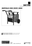
CITOMIG 300 / 400 / 500 XP Manuel d’emploi et d’entretien / Conserver ce livret d’instruction GB Manuel d’emploi et d’entretien / Keep this instruction manual FR Cat n° : W 000 261 592 Rev : A Date : 07/06 Contact : www.saf-fro.com Le soudage à l'arc et le coupage plasma peuvent être dangereux pour l'opérateur et les personnes se trouvant à proximité de l'aire de travail. Lire le manuel d'utilisation et l'instruction de sécurité. Arc welding and plasma cutting may be dangerous for the operator and persons close to the work area. Read the operating manual and Safety instructions SOMMAIRE CONTENTS 1 - INFORMATIONS GENERALES..............................................................................2 1.1. COMPOSITION DE L'ENSEMBLE DE BASE................................................2 1.2. DESCRIPTION ...............................................................................................2 1.3. CARACTERISTIQUES TECHNIQUES ..........................................................3 1.4. DIMENSIONS ET POIDS...............................................................................3 1.5. DEVIDOIRS ....................................................................................................3 1.6. CARACTERISTIQUES TECHNIQUES DU DEVIDOIR .................................3 1.7. TORCHES ......................................................................................................3 1 - GENERAL INFORMATION..................................................................................... 2 1.1. CONSTITUENT ITEMS OF BASIC ASSEMBLY........................................... 2 1.2. DESCRIPTION .............................................................................................. 2 1.3. TECHNICAL SPECIFICATIONS ................................................................... 3 1.4. DIMENSIONS AND WEIGHT ........................................................................ 3 1.5. WIRE FEED UNIT.......................................................................................... 3 1.6. WIRE FEED UNIT TECHNICAL SPECIFICATIONS..................................... 3 1.7. TORCH .......................................................................................................... 3 2 - MISE EN SERVICE..................................................................................................4 2.1. PROCESSUS D'INSTALLATION...................................................................4 2.2. BRIDE FAISCEAU..........................................................................................5 2 - STARTING UP ........................................................................................................ 4 2.1. INSTALLATION PROCESSUS...................................................................... 4 2.2. BRIDLE HARNESS........................................................................................ 5 3 - INSTRUCTIONS D’EMPLOI....................................................................................6 3.1. ALIMENTATION / MISE EN ROUTE / ARRET..............................................6 3.2. FONCTIONS PRINCIPALES .........................................................................6 3.3. AIDE AUX REGLAGES (E.S.P.) ....................................................................9 3.4. REGLAGE DU CYCLE.................................................................................10 3.5. ASSISTANCE AUX DIAGNOSTICS DES INCIDENTS ...............................12 3.6. CHANGEMENT DES PIECES D'USURE ....................................................13 3 - INSTRUCTIONS FOR USE..................................................................................... 6 3.1. ALIMENTATION / START UP / STOP .......................................................... 6 3.2. PRINCIPALES FUNCTIONS......................................................................... 6 3.3. HELP WITH SETTINGS (E.S.P) ................................................................... 9 3.4. CYCLE ADJUSTMENT................................................................................ 10 3.5. TROUBLESHOOTING................................................................................. 12 3.6. CHANGING THE WEAR PART................................................................... 13 OPTIONS.....................................................................................................................14 3.7. PIVOT, REF. W000055048 ..........................................................................14 OPTIONS.................................................................................................................... 14 3.7. SWIVEL, REF. W000055048....................................................................... 14 4 - ENTRETIEN ...........................................................................................................15 4 - MAINTENANCE .................................................................................................... 15 5 - MAINTENANCE.....................................................................................................16 5.1. PIECES DE RECHANGE.............................................................................16 5.2. PROCEDURE DE DEPANNAGE.................................................................17 5 - MAINTENANCE .................................................................................................... 16 5.1. SPARE PARTS............................................................................................ 16 5.2. DIAGNOSIS CHART ................................................................................... 17 SCHEMAS ELECTRIQUES ET ILLUSTRATIONS ....................................................19 ELECTRICAL DIAGRAMS AND FIGURES .............................................................. 19 1 - GENERAL INFORMATION 1 - INFORMATIONS GENERALES 1.1. CONSTITUENT ITEMS OF BASIC ASSEMBLY 1.1. COMPOSITION DE L'ENSEMBLE DE BASE Les CITOMIG 300/400/500 XP sont des installations de soudage MIG-MAG conventionnelle à commutateurs avec système d'aide au réglage. Le CITOMIG 300 XP est équipé de : Ŀ Ö 1 câble d'alimentation, longueur 5 m (section 4x2.5 ), Ŀ Ö 1 câble de longueur 5 m équipé d'une pince de masse (section 35 ), Le CITOMIG 300 XP existe en : The CITOMIG 300/400/500 XP are a conventional switch based MIG-MAG welding installations with system help with setting. The CITOMIG 300 XP is equipped with : Ö 1 length 5 m (section 4x2.5Ƒ) power supply cable Ö 1 length 5 m (section 35Ƒ), cable with earth socket The CITOMIG 300 XP exists as : Version compacte AIR, réf. W000260959 Version séparée AIR, réf. W000260960 Compact AIR Version, ref. W000260959 Separate AIR Version, ref. W000260960 Le CITOMIG 400 XP est équipé de : Ŀ Ö 1 câble d'alimentation, longueur 5 m (section 4x4 ), Ŀ Ö 1 câble de longueur 5 m équipé d'une pince de masse (section 70 ), Le CITOMIG 400 XP existe en : Version compacte AIR, réf. W000260961 Version compacte EAU, réf. W000260962 Version séparée AIR, réf. W000260964 Version séparée EAU, réf. W000260963 The CITOMIG 400 XP is equipped with : Ö 1 length 5 m (section 4x4Ƒ) power supply cable Ö 1 length 5 m (section 70Ƒ), cable with earth socket The CITOMIG 400 XP exists as : Compact AIR Version, ref. W000260961 Compact WATER Version , ref. W000260962 Separate AIR Version, ref. W000260964 Separate WATER Version , ref. W000260963 Le CITOMIG 500 XP est équipé de : Ŀ Ö 1 câble d'alimentation, longueur 5 m (section 4x10 ), Ŀ Ö 1 câble de longueur 5 m équipé d'une pince de masse (section 95 ), The CITOMIG 500 XP is equipped with : Ö 1 length 5 m (section 4x10Ƒ) power supply cable Ö 1 length 5 m (section 95Ƒ) cable with earth socket Le CITOMIG 500 XP existe en : Version séparée AIR, réf. W000260965 Version séparée EAU, réf. W000260966 The CITOMIG 500 XP exists as : Separate AIR Version, ref. W000260965 Separate WATER Version, ref. W000260966 Les références des versions séparées des CITOMIG 300/400/500 XP ne comprennent pas les dévidoirs. 1.2. DESCRIPTION ( Voir dépliant FIGURE 1, 2, 9 et 10 à la fin de la notice) Bouton marche / arrêt Potentiomètre de réglage vitesse fil Sélecteur de mode Bouton choix affichage : vitesse de fil/intensité de soudage/tension Commutateur sélection tension de soudage Afficheur Embase DINSE : câble de masse pôle Embase DINSE : choix de la valeur de self pôle + Branchement torche Bouton avance fil manuel / purge gaz Chaîne blocage bouteille Branchement câble commande faisceau (version séparée) IMPORTANT : utiliser toujours les 2 anneaux d’élinguage pour le levage du générateur. 2 The references of the separate CITOMIG versions 300/400/500 XP do not include wire feed units. 1.2. DESCRIPTION ( See fold-out FIGURE 1 ,2 ,9 and 10 at the end of the manual) 1 2 3 4 5 6 7 8 9 10 11 12 On/Off switch Adjusting potentiometer wire speed Mode selector Button display choice selector of wire feed/welding intensity/tension Welding voltage selector-switch Display Socket DINSE : - pole earthing cable Socket DINSE : choice of + pole choke value Torch connecting The manual wire feed / gas bleed button Cylinder immobilising chain Cable control harness connection (separated version) IMPORTANT : always use 2 slinging attachments to lift the power source. CITOMIG 300/400/500 XP 1.3. TECHNICAL SPECIFICATIONS 1.3. CARACTERISTIQUES TECHNIQUES PRIMAIRE Nombre de phases / fréquence Alimentation Courant absorbé à 40% Courant absorbé à 50% Courant absorbé à 60% Courant absorbé à 100% Puissance absorbée à 100% Puissance absorbée à 60% Puissance absorbée à 50% SECONDAIRE Tension à vide Uo Courant de soudage Températures ambiantes Facteur de marche à 40% Facteur de marche à 45% Facteur de marche à 50% Facteur de marche à 55% Facteur de marche à 60% Facteur de marche à 100% Indice de protection Classe d'isolation Norme SCITOMIG 300 XP CITOMIG 400 XP CITOMIG 500 XP 3 ~/50 HZ 230V / 400 V 27.7 A / 16 A 22 A / 12.7 A 16.8 A / 9.7 A 6.8 KVA 8.9 KVA 11.2 KVA 3 ~/50 HZ 230V / 400 V 47 A / 27 A 37 A / 22 A 30 A / 17 A 12 kVA 15.1 kVA 18.9 kVA 3 ~/50 HZ 230V / 400 V 63.3 A / 36.6 A 50 A / 28.9 A 40.3 A / 23.3 A 16.2 kVA 20.1 kVA 25.2 kVA 16.5 – 35.8 V 30 A à 280 A 25° C 40°C 270 A 270 A 240 A 200 A 200 A 16.6 – 45.8 V 15.8 – 50.4 V 28 A à 380 A 16 A à 480 A 25° C 40°C 25° C 40°C 380 A 380A 480A 480A 320A 410A 300A 280A 370A 350A IP 23 H EN 60974-1 / EN 60974-10 (CEM) Caractéristiques techniques de la torche : x consulter l'instruction d'emploi (nous consulter) PRIMARY Number of phases / frequency Power supply Current consumption 40% Current consumption 50% Current consumption 60% Current consumption 100% Power consumption 100% Power consumption 60% Power consumption 50% SECONDARY No load voltage Welding current Ambient temperatures Duty cycle 40% Duty cycle 45% Duty cycle 50% Duty cycle 55% Duty cycle 60% Duty cycle 100% Degree of protection Insulation class Standard Technical specifications of torch : x refer to instructions for use (consult us). Degrés de protection procurés par les enveloppes Degrees of protection provided by the covering Lettre code Code letter IP Protection du matériel Equipment protection Premier chiffre First number 2 Contre la pénétration de corps solides étrangers de t 12,5 mm Against the penetration of solid foreign bodies with t 12,5 mm Deuxième chiffre Second number 1 Contre la pénétration de gouttes d'eau verticales avec effets nuisibles Against the penetration of vertical drops of water with harmful effects 3 Contre la pénétration de pluie (inclinée jusqu'à 60° par rapport à la verticale) avec effets nuisibles Against the penetration of rain (inclined up to 60° in relation to the vertical) with harmful effects 1.4. DIMENSIONS ET POIDS Source CITOMIG 300 XP Source CITOMIG 400 XP Source CITOMIG 500 XP DV 4004XP / DV 4004 XPW Dimensions (Lxlxh) Dimensions (LxWxH) 780 x 390 x 825 mm 925 x 580 x 1060 mm 925 x 580 x 1060 mm 610 x 330 x 510 mm Poids net Net weight 98 kg 161 kg 201 kg - Poids emballé Packaging weight 121 kg 186 kg 225 kg - 1.4. DIMENSIONS AND WEIGHT CITOMIG 300 XP power source CITOMIG 400 XP power source CITOMIG 500 XP power source DV 4004XP / DV 4004 XPW 1.5. WIRE FEED UNIT 1.5. DEVIDOIRS Les DEVIDOIRS DV 4004XP / DV 4004 XPW sont destinés au soudage MIGMAG. The DV 4004XP / DV 4004 XPW wire feed units are designed for MIG-MAG welding. Version AIR DV 4004 XP / AIR version DV 4004 XP Version EAU DV 4004XPW / WATER version DV 4004XPW réf. / ref. réf. / ref. Faisceau 5 m / 5 m harness W000260999 W000261001 Faisceau 10 m / 10 m harness W000261000 W000261002 1.6. CARACTERISTIQUES TECHNIQUES DU DEVIDOIR Platine double Vitesse de dévidage Régulateur vitesse fil Fils utilisables Passe par un trou d'homme Connexion torche 1.7. TORCHES ( Voir FIGURE page 18) CITOMIG 300/400/500 XP 1.6. WIRE FEED UNIT TECHNICAL SPECIFICATIONS 4 galets / 4 rollers 1 20 m / mn Tachymétrique Tachometer 0.8 2.4 mm Oui (sans chariot) Yes (without trolley) « Type Européen » « European type » Twin plate Wire feed speed Wire speed regulation Wire dia. usable Fit through a manhole Torch connection 1.7. TORCH ( See FIGURE page 18 ) 3 2 - STARTING UP 2 - MISE EN SERVICE ATTENTION : la stabilité de l'installation est assurée jusqu'à une inclinaison de 10°. CAUTION : equipment stability is ensured up to an angle of 10°. 2.1. INSTALLATION PROCESSUS 2.1. PROCESSUS D'INSTALLATION Step 1 Etape 1 Les CITOMIG XP sont livrés avec le câble primaire branché dans le générateur et couplé en 400V triphasé. The CITOMIG XP are delivered with the primary cable connected to the power-source and coupling 400V threephases. Si votre réseau correspond à une autre tension d'alimentation, il est nécessaire de changer le couplage à l'intérieur de la source de puissance : Ö mettre le poste hors tension Ö enlever le panneau droit du générateur Ö coupler conformément à l’étiquette ci-contre la plaque à bornes et le transformateur auxiliaire. Ö remonter le panneau droit du générateur If your electric network corresponds to another power supply voltage, it is necessary to change the coupling inside the power source. Ö turn the welding set OFF Ö remove the right panel of the power-source Ö Make connections between the terminal plate and auxiliary transformer as shown on the adjacent label Ö fit the right panel back on Step 2 Etape 2 Monter sur le câble primaire une prise mâle (triphasée + terre). Fit a three-phase + earth plug on the primary cable. The power supply must be protected by a fuse or circuit breaker with a rating corresponding to the maximum primary consumption of the generator (see page 3 ) depending on the power supply voltage. L'alimentation doit être protégée par un dispositif de protection (fusible ou disjoncteur) de calibre correspondant à la consommation primaire maximum du générateur (voir page 3 ) suivant la tension d'alimentation délivrée. YOUR MAINS SUPPLY MUST DELIVER: 230/400V (r10%) 50 Hz three-phase VOTRE RESEAU DOIT DELIVRER : 230/400V (r10%) 50 Hz triphasé Step 3 Etape 3 Vérifier que l'interrupteur 0/1 à l'arrière du poste est sur position 0 (arrêt). Check that the 0/1 switch at the rear of the unit is set to 0 (OFF). Step 4 Placer la bouteille sur le porte bouteille et la sécuriser avec la fixation. Raccorder le tuyau gaz à la bouteille ou au réseau Place the cylinder on the cylinder holder and secure it with the fastening system. Etape 4 Connect the gas hose to the cylinder or the mains IMPORTANT : Veillez à bien arrimer la bouteille de gaz en mettant en place la sécurité. Veillez régulièrement au bon état du système d’attache. Etape 5 version dévidoir intégré x Etape 5 Step 5 version dévidoir séparé x Brider le faisceau du dévidoir à l’aide du collier monté sur le panneau latéral gauche. x Raccorder le faisceau du dévidoir sur la face avant version with built-in wire feed unit x Brancher la torche de soudage sur l’embase du poste Step 5 Connect the welding torch to the socket on the welding set version with external wire feed unit x Clamp the harness of the wire feed unit using the collar fitted on the left-hand side panel. x Connect the wire feed unit harness to the front panel Step 6 Etape 6 x Brancher la torche de soudage sur l’embase du dévidoir x Connect the welding torch to the socket on the wire feed unit x Si la torche est refroidie à l’eau, raccorder les entrées et sorties circuit de refroidissement suivant le cas, sur le générateur ou sur le dévidoir x If the torch is water-cooled, connect the cooling circuit inputs and outputs, as the case may be, to the generator or wire feed unit. x Raccorder le connecteur du câble de masse sur le pôle négatif du générateur. Raccorder la pince crocodile au plus près de la soudure à réaliser. Raccorder le connecteur mâle du générateur (installation à dévidoir interne) ou le faisceau du dévidoir (installation à dévidoir sorti) sur le pôle positif en fonction de la valeur de self souhaitée. x Connect the earth cable connector to the negative pole of the generator Connect the crocodile clip as close as possible to the welding to be carried out Connect the male connector of the generator (installation with internal wire feed unit) or the wire feed unit harness (installation with external wire feed unit) to the positive pole according to the required choke value Step 7 Etape 7 x x 4 IMPORTANT : Be careful to secure the gas cylinder by putting a safety in place. Check the condition of the fastening system regularly x x CITOMIG 300/400/500 XP Nota : Pour certains fils fourrés, inverser les polarités. Note : For some flux-cored wires the polarities must be reversed. Choix de la valeur de self x Utilisation pour le soudage MIG/MAG sous gaz purs ou gaz mixtes x Arc doux cordon "mouillé" Selecting the choke value x Use for MIG/MAG welding under pure or mixed gases x "Wetted" bead soft arc x Utilisation pour le soudage MIG/MAG sous gaz purs ou gaz mixtes x Use for MIG/MAG welding under pure or mixed gases x Arc dynamique et pénétrant x Dynamic, penetrating arc Etape 8 Step 8 x Raccorder la prise mâle d'alimentation sur le réseau x Connect the power supply plug to the mains 2.2. BRIDLE HARNESS 2.2. BRIDE FAISCEAU Elle permet le maintien du faisceau côté générateur. Elle ne concerne que les générateurs avec dévidage séparé. Le montage d’effectue : Ö en positionnant la bride à l’extrémité de la gaine qui protège le faisceau Ö puis en montant celle-ci sur le côté du générateur, en utilisant les vis de fixation du panneau (photo ci dessous) It’s used to hold the harness on the side of the generator. It concerns the generators with separated wire feed. Assembly : Ö Positioning the bridle at the end of the sheath which protects the harness. Ö Then mounting this on the generator side, and using panel fixing screws (see below) Bride faisceau Bridle harness CITOMIG 300/400/500 XP 5 3 - INSTRUCTIONS FOR USE 3 - INSTRUCTIONS D’EMPLOI 3.1. ALIMENTATION / START UP / STOP 3.1. ALIMENTATION / MISE EN ROUTE / ARRET Step 1 Etape 1 x x Effectuer correctement le processus d'installation indiqué en page 4. Carefully follow the installation procedure on page 4. Step 2 Etape 2 x Basculer l'interrupteur 0/1 sur la position 1 à l'arrière du générateur. L’afficheur (repéré 6) indique : x pendant 2s, la version du générateur pendant 2s, la version du programme - x Set the 0/1 switch at the back of the generator to 1 x The display panel (item 6) shows - the generator version for 2 s the programme version for 2 s Simultanément le ventilateur et le groupe de refroidissement (s’il existe) sont activés durant 4s. The fan and cooling group (if there is one) are activated for 4 s. Step 3 x x Etape 3 x x x x x x Monter le tube contact adapté au diamètre et au type de fil utilisé, Libérer le système de pression des galets, Monter le galet correspondant au diamètre et au type de fil utilisé, Engager le fil manuellement jusque dans l'adaptateur, Positionner la torche et son faisceau de la manière la plus droite possible, Refermer le système de pression, Appuyer sur le bouton avance fil jusqu'à la sortie du fil au niveau du tube contact. Fit the contact tube corresponding the diameter and type of wire used, Release the roller pressure system, Fit the roller corresponding the diameter and type of wire used, Insert the wire manually until it enters the adapter, Position the torch and its harness as straight as possible, Close the pressure system, Press the wire feed button until the wire comes out at the contact tube. x x x x x x if an air torch is used with a generator fitted with cooling unit, the water input and output must always be connected via the shunt delivered with the generator. En cas d’utilisation d’une torche air avec un générateur équipé d’un groupe de refroidissement, relier impérativement l’entrée et la sortie EAU par le shunt livré avec le générateur. 3.2. PRINCIPALES FUNCTIONS 3.2. FONCTIONS PRINCIPALES ( Voir dépliant FIGURE 6 à la fin de la notice) Les CITOMIG XP ont été conçus pour permettre un accès simple et intuitif, à tous les paramètres de réglage nécessaires à une utilisation professionnelle du soudage semiautomatique. ( See fold-out FIGURE 6 at the end of the manual) CITOMIG XP sets have been designed to allow straightforward, intuitive access to all setting parameters required for professional semi-automatic welding. 1. Sélecteur de cycle (CM3) ( Voir dépliant FIGURE 7 à la fin de la notice) Actionner ce sélecteur pour accéder aux 4 modes de soudage x Mode 2 temps : L’appui permanent sur la gâchette permet d’enchaîner le pré gaz d’une durée prédéterminée, l’amorçage et le soudage. Le relâchement de la gâchette permet l’arrêt du soudage suivi du post gaz d’une durée prédéterminée. La reprise du soudage pendant la phase de post gaz s'effectue sans pré gaz. x x Mode 4 temps : Le premier appui sur la gâchette enclenche le pré gaz, démarre l’amorçage et le soudage. Le deuxième appui sur la gâchette arrête le soudage et déclenche le post gaz jusqu’au relâchement. Mode Point : Le fonctionnement est identique au mode 2T mais le temps de soudage ne peut excéder la valeur programmée. Utilisation : Ö Sélectionner le mode 2T et régler la vitesse fil avec P2. Ö Sélectionner le mode point, l’afficheur indique Pt durant 2s, puis le dernier temps programmé durant 2s. Pour corriger ce dernier, utiliser P2. 6 1. Cycle selector (CM3) ( See fold-out FIGURE 7 at the end of the manual) Actuate this selector to access four welding modes : 2-action cycle : If the trigger is pressed continuously the pre-gas phase runs for a preset time , followed by striking and welding. When the trigger is released, the end of welding operation runs followed by the post-gas phase for a preset time . If welding is resumed during the post-gas phase the pre-gas phase is not repeated. x x 4-action cycle : The first press on the trigger activates the pre-gas, and starts striking and welding. The second press on the trigger stops welding and starts the post-gas until release. x Spot mode: Operation is identical to 2T mode but the welding time cannot exceed the programmed value. Use : Ö Select 2T mode and set the wire speed with P2. Ö Select spot mode; the display shows Pt for 2 s, then the last programmed time for 2 s. To change this time, use P2. CITOMIG 300/400/500 XP x Mode Intermittent : Le fonctionnement est identique au x Intermittent mode: Operation is identical to spot mode. mode point. Si la gâchette reste appuyée après l’arrêt If the trigger remains pressed after welding stops, a du soudage, un nouveau point démarre après un temps new spot starts after a time defined P2. défini à l’aide de P2. Utilisation : Use : Ö Sélectionner le mode 2T et régler la vitesse fil Ö Select 2T mode and set the wire speed with P2. avec P2. Ö Sélectionner le mode point, l’afficheur indique Pt Ö Select spot mode; the display shows Pt for 2 s, durant 2s, puis le dernier temps programmé then the last programmed time for 2 s. To change durant 2s. Pour corriger ce dernier, utiliser P2. this time, use P2. Ö Sélectionner le mode intermittent, l’afficheur Ö Select intermittent mode; the display shows It 2s, for 2 s, then the last programmed time for 2 s. To indique It 2s, puis le dernier temps programmé change this time, use P2. durant 2s. Pour corriger ce dernier, utiliser P2. Nota : 2. Pour les modes Point et Intermittent, à chaque variation de P2, l’afficheur indique la valeur du temps pendant 2 secondes. For Spot and Intermittent modes, each time P2 is changed, the display shows the time value for 2 seconds. Note : 2. Display selector (CM4) Sélecteur d'affichage (CM4) Initialisation of help with settings Initialisation de l’aide aux réglages x Cette sélection permet d’activer l’aide aux réglages et de sélectionner le type de consommable utilisé soit : nature du gaz de protection, nature et diamètre du métal d’apport. Ces informations sont nécessaires à l’utilisation de la fonction d’assistance aux réglages. x x Le sélecteur d’affichage permet de choisir le paramètre à visualiser. Le tableau suivant indique la valeur affichée en fonction de l’utilisation : x Paramètres à visualiser This selection allows activation using the settings and selection of the consumable used, i.e.: Type of protection gas, Type and diameter of filler metal. This information is required for using the setting assistance function. Parameters to be displayed The display selector is used to choose the parameter to be displayed. The following table shows the value displayed depending on the use : Utilisation de l’installation / Use of installation Affichage suivant la position de CM4 : Display following the position of CM4 : Hors soudage / No welding Avec aide au réglage / With help with settings Epaisseur à souder en mm / Thickness to be welded in mm Position de CM5 et CM6 puis de la sortie de self / Position of CM5 and CM6 and of the self output Sans aide au réglage / Without help with settings --- --- Intensité de soudage en ampère / The welding current in Amp. Tension de soudage en volt / The welding voltage in V. En soudage / During welding Vitesse fil ajustable par P2 en m/mn / Wire feed speed, adjustable by P2, in m/mn L’information RI soudage est visualisée par le point digital du troisième afficheur qui clignote pendant le soudage. The welding current relay information is displayed by the digital point of the third display unit, which blinks during welding. A la fin du soudage, pendant 10 secondes, les dernières valeurs mesurées sont mémorisées. On peut les afficher en plaçant CM2 sur les positions U ou I. Pendant ces 10 secondes, le point digital du troisième digit reste allumé. When welding ceases, for 10 seconds, the last values measured are memorized. They can be displayed by placing CM2 on positions U or I. The digital point of the third display unit remains steady for these 10 seconds. 3. 3. Voltage switch (CM5 and CM6) Commutateurs de tension (CM5 et CM6) CM 5 CITOMIG 300 XP CM5 CITOMIG 400 / 500 XP CITOMIG 300/400/500 XP CM6 CITOMIG 400 / 500 XP Les commutateurs de tension permettent d’appliquer la tension désirée aux bornes du circuit de soudage. Le système d’assistance aux réglages indique une position du commutateur adapté à l’application donnée (voir § 3.3. AIDE AUX REGLAGES). A titre indicatif, le tableau suivant donne la liste des tensions à vide en fonction de la position des commutateurs de tension. The voltage selector switch is used to apply the required voltage to the welding circuit terminals. The help with settings system shows a suitable position of the selector switch for a given application (see § 3.3. HELP WITH SETTINGS). For guidance, the following table provides a list of no-load voltages corresponding to the position of the voltage selector. 7 Ces valeurs s’entendent pour une tension d’alimentation identique à la tension assignée. Un bref appui sur la gâchette, sans amorcer d'arc, permet de lire la tension à vide sur l'afficheur. Nota : 300 XP 4. Note : These values are given for a power supply voltage identical to the assigned voltage. If the trigger is pressed very briefly, without igniting the arc, the no-load voltage can be read on the display. 400 XP CM5 Tensions 1 2 3 4 5 6 7 8 9 10 16,7 V 17,5 V 18,4 V 19,6 V 20,8 V 22,1 V 23,7 V 25,4 V 27,3 V 29,9 V 11 12 32,6 V 35,6 V CM6 CM5 1 2 3 4 5 6 7 8 9 10 500 XP A B C 16,7 V 17,1 V 17,6 V 17,9 V 18,4 V 18,9 V 19,4 V 19,9 V 20,4 V 20,8 V 21,5 V 22,2 V 22,8 V 23,5 V 24,3 V 25,1 V 25,9 V 26,8 V 27,8V 28,7V 30 V 31,3 V 32,6 V 33,9 V 35,6 V 37,2 V 39 V 41,3 V 43,5 V 45,8 V CM6 CM5 1 2 3 4 5 6 7 8 9 10 A B C 15,8 V 16,2 V 16,6 V 17,1 V 17,5 V 18 V 18,5 V 19,1 V 19,7 V 20,2 V 20,9 V 21,7 V 22,4 V 23,1 V 24 V 24,8 V 25,6 V 26,7 V 27,9 V 29 V 30,4 V 31,9 V 33,6 V 35,1 V 37,2 V 39 V 41,1 V 44,1 V 47,5 V 50,4 V 4. Gas bleed and wire feeding (BP 10) Purge gaz et avance fil (BP 10) Le bouton poussoir permet d’accéder aux fonctions purge gaz et avance The pushbutton provides access to the gas bleed and manual wire feed fil manuel. functions. purge gaz : la fonction est accessible par un appui bref (inférieur à 0.5s), la purge du circuit de gaz dure 7s et la durée restante est affichée. dévidage fil manuel : la fonction est accessible par un appui continu de durée supérieure à 0,5 s. Le dévidage s’arrête au relâchement du bouton poussoir. La vitesse de dévidage fil manuel correspond à la vitesse de dévidage réglée par P2. La fonction est aussi accessible durant la purge gaz. Gas bleed : The function is accessed by a short press (less than 0.5 s), the gas circuit bleed lasts 7 s and the time remaining is displayed on the screen. Manual wire feed : The function is accessed by keeping the button pressed for more than 0.5 s. The wire feed stops when the button is released. The manual wire feed rate corresponds to the welding feed rate and can be adjusted via the wire rate setting potentiometer P2. The function can be accessed during the gas bleed In help with settings initialisation mode: used to move from one parameter to another. en mode initialisation de l’aide aux réglages : permet de passer d’un paramètre à un autre. 5. Nota : 8 5. Potentiometer (P2) Potentiomètre (P2) La fonction du potentiomètre dépend de la position des commutateurs de cycle (CM3). The function of the potentiometer depends on the position of the cycle selector switches (CM3). x En mode 2T ou 4T : Suivant la position de CM4, le potentiomètre de réglage permet : - de modifier la vitesse de dévidage entre 1 et 20 m/min. - d'afficher la vitesse fil réglée, l'épaisseur de tôle ou les positions des commutateurs de tension et de la position de self si le mode assistance aux réglages est activé (voir § 3.3). x x En mode point ou intermittent : Le potentiomètre permet de régler les temps de point ou d’arrêt de 0 à 10s. x In spot or intermittent mode : The potentiometer is used to set the spot time or stop time from 0 to 10 s . x En mode paramétrage de l’aide aux réglages : Le potentiomètre permet de sélectionner les valeurs des paramètres. x In help with settings configuration mode: The potentiometer is used to select the parameter values. Dans le cas des versions séparées, l'option potentiomètre sur dévidoir se substitue au réglage de vitesse fil sur le générateur. Le potentiomètre (P2) du générateur n’est utile qu’en mode point ou intermittent pour régler les temps. Pour être détecté, le potentiomètre du dévidoir doit être dans une position différente de 0 à la mise sous tension du générateur. Note : In 2T or 4T : Depending on the position of CM4, the setting potentiometer is used: - to set the wire feed speed between 1 and 20 m/mn. - to display the set wire speed, sheet thickness or positions of the voltage and choke position selector switches if help with settings mode is activated (see § 3.3). For separate versions, the potentiometer option on the wire feed unit replaces the wire speed setting on the generator. The generator potentiometer (P2) is only used in spot or intermittent mode to set the times. To be detected, the wire feed potentiometer must be in a position other than 0 when the generator voltage is switched on CITOMIG 300/400/500 XP 3.3. HELP WITH SETTINGS (E.S.P) 3.3. AIDE AUX REGLAGES (E.S.P.) Le CITOMIG XP possède un module d’assistance aux réglages : en choisissant l'épaisseur à souder, le générateur donne la position du sélecteur de self et la tension de soudage conseillée. The CITOMIG XP has a help with settings module: after the welding thickness is selected, the generator gives the position of the choke selector and recommended welding voltage. Procédure / Procedure Impulsion sur BP10 / Pressure on PB10 Par P2 sélection des « consommables utilisés » ou du « dynamisme de l’arc » dans les choix proposés sur l’afficheur / Use P2 to select « consumables used » or « dynamism of the arc » from the options offered in the display « P2 au mini » / « P2 minimum » « mini P2 < position P2 >maxi P2 » ou « un seul choix possible » / »Min. P2 < position P2 > max. P2 » or « only one choice possible » « P2 au maxi » / « P2 maximum » Paramétrage / Setting parameters Affichage = « OFF » : Début / display = « OFF » : start (activation aide aux réglages avec P2 au max. / activation settings help with P2 max) 1 ière impulsion / 2 ième impulsion / 3 ième impulsion / 4 ième impulsion / 1 st pressure 2 nd pressure 3 rd pressure 4 th pressure Nature du fil / Nature of wire Tous générateurs / All generators Diamètre du fil en mm / Diameter of wire in mm Suivant le générateur / According to generator 300A 400A 0.8 0.8 1 1 1 1.2 1.2 1.2 0.8 0.8 1 1 1 1.2 1.2 1.2 Nature du gaz / Nature of gas Dynamisme de l’arc / Dynamism of the arc Tous générateurs / All generators Tous générateurs / All generators 500A Atal 5 1.6 Acier / Steel CO2 HARD 1.6 0.8 0.8 1 1 1 1.2 1.2 1.2 Arcal 21 1.6 0.8 Inox 0.8 1 1 1 1.2 1.2 1.2 Noxalic 12 1.6 Alu Fil fourré acier avec laitier / Core wire steel with slag 1 1.2 1 1.2 1.0 1.2 SOFT Argon 1.2 1.2 1.6 1.2 1.6 1.6 Atal 5 2.4 5 ième impulsion / 5 th pressure Affichage = « END » : Fin / Display = « ON » : End CITOMIG 300/400/500 XP 9 1. Utilisation du module d'assistance ( Voir dépliant FIGURE 8 à la fin de la notice) x x x x x x Placer le sélecteur de mode (CM3) sur le mode de soudage impulsion ou 2T. Placer le sélecteur d’affichage (CM4) sur la position intensité/épaisseur. Modifier le réglage du potentiomètre de vitesse fil (P2) jusqu’à afficher l’épaisseur de la pièce à souder. Dans le cas d’un générateur à dévidoir séparé équipé de son option potentiomètre sur dévidoir, utiliser le potentiomètre du dévidoir. Placer le sélecteur d’affichage (CM4) sur la position tension / assistance aux réglages. Lire les indications d’assistance aux réglages sur l’afficheur puis positionner les commutateurs de tension (CM5 et CM6) et se raccorder sur la sortie de self indiquée. Commencer le soudage et, si nécessaire, ajuster finement le réglage à l’aide de P2. 2. Using the help module ( See fold-out FIGURE 8 at the end of the manual) x x x Set the mode selector (CM3) to impulsion or 2T welding mode. Set the display selector (CM4) to the current/thickness position. Modify the wire speed potentiometer (P2) until the thickness of the part to be welded is displayed. For a generator with separate wire feed unit that has the potentiometer option, use the wire feed unit potentiometerr. x Set the display selector (CM4) to the voltage/help with settings position. x Read the help with settings information on the display unit then set the voltage selectors (CM5 et CM6) and connect to the indicated choke output. x Start welding and, if necessary; fine-tune the setting using P2. 3.4. CYCLE ADJUSTMENT 3.4. REGLAGE DU CYCLE Les CITOMIG XP permettent d’accéder à la totalité des paramètres de réglages du cycle de soudage. Paramètres réglables : Adjustable parameters : PrG Pré gaz Pre-gas VL Amorçage à vitesse lente Striking at low wire speed ShL Dynamisme d’arc à l’amorçage Dynamism of arc on striking Post-retract Post-retract Post gaz Post-gas Pr PoG Chronogramme du cycle de soudage : Accès au mode « paramétrage du cycle » 1. Le poste hors tension, maintenir BP10 appuyé 2. BP10 toujours maintenu appuyé, mettre le poste sous tension 3. Lorsque « CYC » apparaît à l’affichage, relâcher BP10 Une fois entré dans ce menu déroulant, il est obligatoire de le parcourir jusqu’à sa fin par 13 appuis successifs sur BP10. Paramétrage du cycle Une impulsion sur BP10 affiche le paramètre modifiable. Après l’impulsion suivante sur BP10, modification possible du paramètre par P2. 10 All welding cycle setting parameters can be accessed on the CITOMIG XP. Welding cycle timing diagram : Access to « Set Cycle parameters » mode 1. With set switched off, hold PB10 down 2. With PB10 still held down, switch on the power supply 3. When « CYC » appears in display, release PB10 Once this pull-down menu is opened, it must be run through to the end by pressing PB10 thirteen times in succession. Setting cycle parameters Press PB10 once to display the parameter for modification After pressing PB10 again, the parameter can be modified with P2 CITOMIG 300/400/500 XP Fonction sélectionnée / Function selected Action / Action Accès au paramétrage du cycle Access to cycle parameters settings Pendant la mise sous tension du poste, BP10 maintenu appuyé While switching on the power supply to the set, hold PB10 down Réglage du temps de pré-gaz Adjusting pre -gas time 1 ière impulsion sur BP10 1 st pressure on PB10 2 ième impulsion sur BP10 Réglage usine = « 0.20 » s Modification réglage par P2 2 nd pressure on PB10 Factory setting = « 0.20 » s Adjust setting with P2 Sélection amorçage avec ou sans vitesse fil lente Selecting strike with or without slow wire speed Sélection et réglage dynamisme d’arc variable à l’amorçage Selecting and adjusting variable dynamism of arc on striking 4 ième impulsion sur BP10 Réglage usine = « YES » Modification réglage par P2 4 th pressure on PB10 Factory setting = “YES” Adjust setting with P2 P2 = 10 Ou / or P2 = 10 P2 = 0 À / to P2 = 10 P2 = 0 À / to 9 ième impulsion sur BP10 9 th pressure on PB10 P2 = 10 P2 = 0 À / to 11 ième impulsion sur BP10 11 th pressure on PB10 12 ième impulsion sur BP10 Réglage usine = « FAc » Modification réglage = « Ent » 12 th pressure on PB10 Factory setting = “Fac” Change settings = “Ent” Retour à l’utilisation du poste Back to operation of set P2 = 0 7 ième impulsion sur BP10 7 th pressure on PB10 10 ième impulsion sur BP10 Réglage usine = « 0.50 » s Modification réglage par P2 10 th pressure on PB10 Factory setting = “0.50” s Adjust setting with P2 Fin de paramétrage du cycle End of setting cycle parameters À / to 5 ième implusion sur BP10 5 th pressure on PB10 8 ième impulsion sur BP10 Réglage usine = « 0.07 » s Modification réglage par P2 8 th pressure on PB10 Factory setting = “0.07” s Adjust setting with P2 Réglage du temps de post-gaz Adjusting post-gas time P2 = 10 P2 = 0 3 ième impulsion sur BP10 3 rd pressure on PB10 6 ième impulsion sur BP10 Réglage usine = « 0.75 » s Modification réglage par P2 6 th pressure on PB10 Factory setting = “0.75” s Adjust setting with P2 Réglage du post-rétract Adjusting post-retract Affichage / Display 13 ième impulsion sur BP10 13 th pressure on PB10 P2 = 10 P2 = 0 Ou / or Affichage fonction des positions de CM3 et de CM4 Display fonction of positions of CM3 and CM4 CITOMIG 300/400/500 XP 11 3.5. ASSISTANCE AUX DIAGNOSTICS DES INCIDENTS Le CITOMIG XP affiche en temps réel la nature des incidents de fonctionnements. Protection thermique : 3.5. TROUBLESHOOTING The CITOMIG XP displays a description of operating faults in real time. Overheating protection : Duty cycle overrun Dépassement facteur de marche Le générateur est verrouillé, la ventilation est déclenchée, le générateur est disponible après quelques minutes. The generator is locked and the fan activated, the generator becomes available again after a few minutes. Protector fault Défaut protecteur Si le défaut persiste, le générateur nécessite un dépannage. If the fault persists, the generator needs to be repaired. Motor protection : Protection moteur : Thermal relay Relais thermique Si la consommation du moteur est trop importante le dévidage s’arrête. La cause peut être un freinage du fil ou un blocage du moteur. Si le défaut persiste, vérifier les pièces d’usures de la torche (Gaine et tube contact). Défaut débit GRE : (si version eau) Indique un défaut de débit du circuit d’eau. Défaut carte : Accès mémoire L'accès à l'aide est impossible, le générateur reste utilisable en mode manuel. 12 If motor power consumption becomes too great, the wire feed stops. The cause may be wire drag or motor jamming. If the fault persists, check the wearing parts of the torch (sheath and contact tube). Cooling unit flow rate fault : (if water version) Indicates a flow rate fault on the water circuit. Card fault : Quick reference access Quick reference function cannot be accessed, the generator cannot be used in manual mode. CITOMIG 300/400/500 XP 3.6. CHANGING THE WEAR PART 3.6. CHANGEMENT DES PIECES D'USURE Ö Pièces d'usure de la platine de dévidage : 0,6 W000160942 0,8 Acierl Steel 1,0 Ö Wire feed plate expendable parts : W000149209 1,2 W000160944 W000162834 W000169577 W000169578 W000160945 1,6 Alu W000148976 W000160943 1.0/1.2 ALUKIT W000255648 1.2/1.6 ALUKIT W000255649 1.6/2.4 ALUKIT W000255650 W000148979 Fil fourré 1.0/1.2 Cored wire 1.2/1.6 W000149209 W000161004 W000162834 W000148979 1.6/2.4 W000257395 W000161005 W000257397 W000148975 CITOMIG 300/400/500 XP W000257331 W000169577 13 OPTIONS OPTIONS 3.7. PIVOT, REF. W000055048 3.7. SWIVEL, REF. W000055048 Cette option utilisée uniquement avec les chariots atelier et chantier de la source de puissance, permet au dévidoir équipé de son propre chariot (et uniquement) de pouvoir pivoter de 180°. This option, which is only used with the workshop and site trolleys, enables the wire feed unit, if it is fitted with its own trolley (and only in this situation), to swivel through 180°. Monter la partie femelle de l’option sur le chariot du dévidoir. Mount the option part female on the wire feed trolley. 14 CITOMIG 300/400/500 XP 4 - MAINTENANCE 4 - ENTRETIEN ATTENTION : Mettre le poste hors tension. La partie maintenance est destinée aux dépanneurs et personnes habilitées. CAUTION : Switch off the unit. The servicing section is intended for repair teams and approved personnel. Entretien du poste Servicing the unit Le poste étant entièrement statique ne demande pratiquement pas d'entretien. As the set is entirely static, it requires virtually no maintenance. ATTENTION TOUS LES MOIS Contrôler le bon état des organes de liaison et le serrage des bornes d'alimentation et de soudage CAUTION EVERY MONTH Check that the connection equipment is in good condition and that the power supply and welding terminals are tight. ATTENTION TOUS LES SIX MOIS Effectuer un nettoyage complet au jet d'air comprimé (après avoir purgé le réservoir du compresseur). Vérifier le serrage des écrous du transformateur, de la plaque à bornes, des câbles, du pont redresseur et des bornes de soudage. CAUTION EVERY SIX MONTHS Clean thoroughly using a compressed air jet (after draining the compressor tank). Check the tightness of the transformer nuts, terminal plate, cables, and rectifier bridge and welding terminals. ATTENTION TOUS LES 2 ANS Remplacer le liquide de refroidissement pour les générateurs équipés de groupe réfrigérant. CAUTION EVERY 2 YEARS Replace the cooling liquid for generators fitted with a cooling unit. Entretien des éléments de dévidage Servicing the wire feed equipment ATTENTION TOUTES LES SEMAINES Nettoyer les galets à la brosse métallique et éventuellement les dégraisser. Vérifier les raccords et la conduite de gaz de manière à éviter les fuites. L'axe support bobine et son dispositif de freinage devront être tenus dans un parfait état de propreté. Huiler très légèrement avec une huile de vaseline pure CAUTION EVERY WEEK Clean the rollers with a metal brush and remove grease if necessary. Check connections and the gas line for leaks. ATTENTION TOUS LES MOIS Vérifier l'état général du moteur. CAUTION EVERY MONTH Check the general condition of the motor. Entretien de la torche The reel support shaft and its braking system must be kept perfectly clean. Apply a very thin coat of pure vaseline oil. Torch servicing ATTENTION TOUTES LES HEURES Dégraisser la buse et l'extrémité du tube contact. Le nettoyage s'effectue tête inclinée vers le bas. Ne pas utiliser d'outil susceptible de rayer la buse. Sur les pièces lisses et propres, les produits aérosol anti-adhérents sont efficaces. CAUTION EVERY HOUR Remove grease from the nozzle and end of the contact tube. Clean with the head pointing down. Do not use a tool capable of scratching the nozzle. Non-stick aerosol products are useful on smooth, clean parts. ATTENTION TOUS LES JOURS Démonter et nettoyer l'âme métallique. Vérifier l'état du tube de contact. EVERY DAY Disassemble and clean the metal core. Check the condition of the contact tube. ATTENTION TOUTES LES SEMAINES Souffler la gaine de protection et d'amenée du fil électrode (sens : têtes vers dévidoir) après avoir retiré l'âme et le guide fil. Nettoyer le guide fil, vérifier son état. CAUTION EVERY WEEK Blow the electrode wire protection and supply duct (direction: heads towards wire feed unit), having first removed the core and wire guide. Clean the wire guide and check its condition Références et conseils d'utilisation : voir notice spécifique torche CITOMIG 300/400/500 XP References and recommendations for use: see specific torch manual. 15 5 - MAINTENANCE 5 - MAINTENANCE 5.1. SPARE PARTS 5.1. PIECES DE RECHANGE ( voir dépliant FIGURES1/2/3/4/5/9/10/11 à la fin de la notice) ( See fold-out FIGURE 1/2/3/4/5/9/10/11 at the end of the manual) Rep. / REF. Item / REF. 300 XP 400 XP W000147489 W000147489 500 XP W000147489 2 5 7/8 10 13 13 13 30 W000147363 W000234654 W000147173 W000147188 / / W000237299 W000148849 W000147363 W000234654 W000147173 W000147188 W000234655 W000183895 / W000148849 W000147363 W000234654 W000148911 W000147188 W000234655 W000235121 / W000148849 14 15 16 18 19 W000147106 W000165944 W000147087 W000147353 W000147343 / W000147286 W000262708 W000163754 / W000153865 W000166213 W000163540 W000147070 W000147072 W000010092 W000137846 / W000148727 W000147114 W000147281 W000148196 W000147351 W000147425 / W000147286 W000262708 W000163754 W000241661 W000153865 W000183897 W000183898 W000148253 W000148249 W000010092 W000137846 W000137849 W000148727 W000147099 W000147271 W000148196 W000147351 W000157012 W000147343 W000147286 W000262708 W000163754 W000241661 W000147888 W000235123 W000235119 W000148253 W000148249 W000010092 W000137846 W000137849 W000148727 W000262863 W000148658 W000148661 W000163284 W000255651 W000262863 W000148658 W000148661 W000163284 W000255651 / / / / / 40 W000255653 W000148698 W000148699 W000149075 W000255653 W000148698 W000148699 W000149075 / / / / 50 51 52 53 54 55 / / / / / / W000148196 W000148018 W000148735 W000148702 W000148730 W000148731 W000010167 W000148196 W000148018 W000148735 W000148702 W000148730 W000148731 W000010167 1 20 21 22 22 23 24 25 26 27 28 29 29 31 32 33 34 35 36/3 7 38 39 16 Description Désignation Commutateur M/A (à l'arrière) Face avant Bouton rouge 21 Poignée de commutateur noire Embase DINSE femelle Interrupteur monostable Commutateur 3 positions Commutateur 10 positions Commutateur 12 positions Poignée de face avant Eléments internes Contacteur Pont de diodes Moteur de ventilation Protecteur thermique pont de diodes Protecteur thermique transformateur Protecteur thermique self TRIAC Carte cycle Transformateur auxiliaire version AIR Transformateur auxiliaire version EAU Shunt mesure de courant Transformateur de puissance Self de puissance Roue arrière Roulette avant Raccord DINSE mâle Fusible cartouche 10x38 (boite de 10) 2A Version AIR Fusible cartouche 10x38 (boite de 10) 4A Version EAU Electrovanne 24V a (versions compactes) Compartiment dévidage Ensemble moto réducteur et platine Kit vis de fixation galet Kit réglage pression Lot engrenages Ensemble chape droite + Ensemble chape gauche On/Off switch ( on the rear) Front panel Red button 21 Black switch handle Female socket DINSE Monostable switch 3 positions selector 10 positions selector 12 positions selector Handle front panel Internal items Capacitor Diode bridge Fan motor Diode bridge thermal protector Transformer thermal protector Self thermal protector TRIAC Cycle card AIR version auxiliary transformer WATER version auxiliary transformer Current measuring shunt Power transformer Power self Rear wheel Front wheel Male socket DINSE 10x38 2A cartridge fuse (box of 10) AIR version 10x38 4A cartridge fuse (box of 10) WATER version 24V a solenoid valve (compact versions) Wire feeding compartment Motor reducing gear set unit and plate Screw set for roller fastening Pressure adjustment unit Batch of gears Right cover unit + Left cover unit Ensemble carter de protection Ensemble embase torche Cache plastique Moyeu axe de bobine Groupe réfrigérant Moteur ventilateur Radiateur Pompe Réservoir Coupleur bleu Coupleur rouge Liquide de refroidissement FREEZCOOL Protective casing unit Socket torch unit Plastic Reel shaft hub Cooling unit Fan motor Radiator Pump Tank Blue coupling Red coupling Cooling liquide FREEZCOOL CITOMIG 300/400/500 XP 5.2. DIAGNOSIS CHART 5.2. PROCEDURE DE DEPANNAGE Servicing operations carried out on electric installations must be performed by persons qualified to do this kind of work (see SAFETY RECOMMENDATIONS section). Les interventions faites sur les installations électriques doivent être confiées à des personnes qualifiées pour les effectuer (voir chapitre CONSIGNES DE SECURITE). CAUSES CAUSES REMEDES NO WIRE-FEED WHEN PRESSING THE TRIGGER + NO MESSAGE DEFECT PAS DE DEVIDAGE EN APPUYANT SUR LA GACHETTE + PAS DE MESSAGE DEFAUT S Torche défectueuse S S Connectique Carte électronique changer la torche shunter les fils de gâchette sur l'embase de torche, si fonctionnement OK Ö changer l'embase de torche si non Ö vérifier la connectique si non Ö changer le CI S Defective torch S S Connection Electronic card Contacteur S Transformateur S Pont redresseur S Carte électronique se mettre en mode 2T puis appuyer sur la gâchette : vérifier que le contacteur s'enclenche vérifier les tensions à la sortie du contacteur appuyer sur la gâchette et vérifier les tensions (AC) en entrée du pont redresseur vérifier les tensions à la sortie du pont redresseur changer le CI S Plastron torche mal positionné ou absent Vérifier positionnement du plastron, appuyer sur bouton de réarmement S Transformer S Rectifier bridge S Electronic card Poste en surcharge S Sécurité thermique (TH1/TH2) S laisser refroidir plusieurs minutes jusqu'à ce que le voyant s'éteigne shunter les sécurités thermiques : Ö si le voyant s'éteint, changer TH1 ou TH2 Ö sinon changer le CI Carte électronique S Coupure câble de soudage Mauvaise ou pas de liaison de masse contrôler les connexions assurer la liaison avec la pièce à souder Torch front plate badly positioned or missing S Overload voltage Mauvaise liaison de masse fixer la masse directement sur la pièce à souder Pour toute intervention interne au générateur en dehors des points cités précédemment : FAIRE APPEL A UN TECHNICIEN CITOMIG 300/400/500 XP Check the positioning of the front plate, press the reset button S Thermal safety (TH1/TH2) S Electronic card let the power source cooling till light goes off shunt thermal safeties : Ö if the light goes off, change the TH1/TH2 Ö otherwise, change the card NO WELDING CURRENT + TORCH TRIGGER PRESSED S S Welding cable cut Earth connection poor or broken check connections connect to the part to be welded MESSY WELDING + STRIKING MAUVAISE PROPRIETE DE SOUDAGE + AMORCAGE S check voltage on rectifier bridge output otherwise, change the card THE RED LAMP IS ON WHEN PRESSING THE TRIGGER PAS DE COURANT DE SOUDAGE + GACHETTE TORCHE ENCLENCHEE S S operating on 2T, check, by pressing the trigger, that the contactor is activated check voltages on contactor output press trigger and check voltages (AC) on rectifier bridge input ABSENCE OF NO-LOAD VOLTAGE + NO WIRE-FEED WHEN PRESSING THE TRIGGER + MESSAGE DEFECT LE VOYANT ROUGE S'ALLUME QUAND ON APPUIE SUR LA GACHETTE S Contactor PAS DE TENSION A VIDE + PAS DE DEVIDAGE EN APPUYANT SUR LA GACHETTE + MESSAGE DEFAUT S change the torch shunt wires of trigger on the torch socket if operation OK Ö change the torch socket if not OK Ö check connections if not OK Ö change the card ABSENCE OF NO-LOAD VOLTAGE WHEN PRESSING THE TRIGGER + NO MESSAGE DEFECT PAS DE TENSION A VIDE QUAND ON APPUIE SUR LA GACHETTE + PAS DE MESSAGE DEFAUT S SOLUTIONS S Poor earth connection secure the earth directly to the part to be welded For any servicing operations internal to the power-source outside the points mentioned previously : CALL IN A TECHNICIAN 17 Références des torches « PROMIG » « PROMIG » torches references Torches pour CITOMIG XP / Torch for CITOMIG XP PROMIG 241 PROMIG 241 W PROMIG 341 PROMIG 341 W PROMIG 441 PROMIG 441 W PROMIG 450 W PROMIG 501 W Torches PROMIG PROMIG torchs Caractéristiques principales / Principal characteristics Facteur de marche torches / Torch duty cycle Longueur du « Air » à 60 % / « Air » at 60 % faisceau / « Eau » à 100% / Lenght of harness Water » at 100 % ATAL ARGON 3m 250 A 220 A 4m 5m 3m 250 A 220 A 4m 5m 3m 320 A 270 A 4m 5m 3m 340 A 320 A 4m 5m 3m 400 A 350 A 4m 5m 3m 400 A 350 A 4m 5m 3m 450 A 400 A 4m 5m 3m 500 A 450 A 4m Refroidies “EAU” Refroidies « AIR » Déconseillées pour les CITOMIG 400 et 500 XP Déconseillées pour les CITOMIG 500 XP Voir les instructions d’emploi (ISEE) pour les caractéristiques détaillées, les consommables et les pièces d’usure. Nous consulter pour les « variantes existantes » sur ces modèles et notre gamme de torches « AZUR » (aspiration de fumées). 18 Références / References Torche / Torch W000145227 W000145228 W000145229 W000145247 W000145248 W000145249 W000145235 W000145236 W000145237 W000145250 W000145251 W000145252 W000145241 W000145242 W000145243 W000145256 W000145257 W000145258 W000144677 W000144678 W000144679 W000144995 W000144996 « WATER » cooled « AIR » cooled Not recommended for CITOMIG 400 and 500 XP Not recommended for CITOMIG 500 XP See user’s instructions (ISEE) for detailed characteristics, consumables and wearing parts. Consult us for current variants on these models and our range of « AZUR » torches (with smoke suction). CITOMIG 300/400/500 XP SCHEMAS ELECTRIQUES ET ILLUSTRATIONS UTILISATION DE L'INSTALLATION AFFICHAGE SUIVANT LA POSITION DE CM4 HORS SOUDAGE AVEC AIDE AU REGLAGE SANS AIDE AU REGLAGE EN SOUDAGE EPAISSEUR A SOUDER (EN MM) INTENSITE DE SOUDAGE EN AMPERES POSITIONS DE CM5 ET CM6 PUIS DE LA SORTIE DE SELF TENSION DE SOUDAGE EN VOLTS VITESSE FIL AJUSTABLE PAR P2 EN M/MN AFFICHAGE SORTIES DE SELF PARAMETRAGE ET UTILISATION DE L'AIDE AU REGLAGE HORS SOUDAGE POSITION CM3 POSITION CM4 AIDE AU REGLAGE OUI NON SELECTION PAR P2 PARAMETRAGE DE L'AIDE AU REGLAGE IMPULSIONS SUR BP 10 1ERE IMPULSION 2EME IMPULSION 3EME IMPULSION NATURE DU FIL DIAMETRE DU FIL NATURE DU GAZ PAR P2 SELECTION DES "CONSOMMABLES UTILISES" DANS LES CHOIX PROPOSES SUR L'AFFICHEUR ELECTRICAL DIAGRAMS AND FIGURES USE OF THE INSTALLATION DISPLAY ACCORDING TO POSITION OF CM4 NO WELDING IN PROGRESS WITH SETTING ASSISTANCE WITHOUT SETTING ASSISTANCE WELDING IN PROGRESS THICKNESS TO BE WELDED (IN MM) WELDING CURRENT IN AMPS POSITIONS OF CM5 AND CM6 THEN OF THE CHOKE OUTPUT WELDING VOLTAGE IN VOLTS WIRE SPEED ADJUSTABLE VIA P2 IN MM DISPLAY CHOKE OUTPUTS PARAMETER SETTING AND USE OF SETTING ASSISTANCE NO WELDING IN PROGRESS CM3 POSITION CM4 POSITION WELDING ASSISTANCE YES NO SELECTION VIA P2 PARAMETER SETTING OF SETTING ASSISTANCE PRESSES ON PB 10 1ST PRESS 2ND PRESS 3RD PRESS TYPE OF WIRE WIRE DIAMETER TYPE OF GAS VIA P2 SELECTION OF "CONSUMABLES USED" FROM THE DISPLAYED CHOICES 4EME IMPULSION SUR BP10 AFFICHAGE "ON" UTILISATION DE L'AIDE AU REGLAGE EN MM, DE L'EPAISSEUR A SOUDER SELECTIONNABLE PAR P2 ALTERNATIVEMENT, DES POSITIONS PRECONISEES POUR : CM5 (A A C) ET CM6 (01 A 10) PUIS DE LA SORTIE DE SELF (M OU N) VOIR : UTILISATION DE L'INSTALLATION REFERENCE DES TORCHES PROMIG POUR SAFMIG 400 ET 500 BLX TORCHES POUR CITOMIG XP CARACTERISTIQUES PRINCIPALES FACTEUR DE MARCHE TORCHES AIR à 60% EAU à 100% LONGUEUR DU FAISCEAU REFERENCES 4TH PRESS OF PB 10 "ON" DISPLAY USE OF SETTING ASSISTANCE IN MM, OF THE WELDING THICKNESS SELECTABLE VIA P2 ALTERNATIVELY, RECOMMENDED POSITION FOR: CM4 (A A C) AND CM6 (01 A 10), THEN OF THE CHOKE OUTPUT (M OR N) SEE: USE OF THE SET PROMIG TORCH REFERENCE FOR SAFMIG 400 AND 500 BLX TORCHES FOR CITOMIG XP MAIN CHARACTERISTICS TORCH DUTY FACTOR AIR at 60% WATER at 100% HARNESS LENGTH REFERENCES VERSION SEPARE / SEPARATED VERSION 1 passage/ 1 run MOT FILTRE CEM CEM FILTER Si PD1 équipé de condensateurs if PD1 equipped condensators MOT EV GACH COMMUN G/EV TACHY AF VF GND NC +5V NC NC TERRE VERSION COMPACT / COMPACT VERSION Platine 4 galets / 4 rolls plate Moteur/Motor Tachy/Tachy COUPLAGE COUPLING côté connexions connections side 1 passage/ 1 run 2A en version AIR 4A en version EAU 2A in WATER version 4A in AIR version Puissance Power CARTE CYCLE CYCLE CARD Gâchette Trigger VERSION RF RF VERSION sortie RAC2 RAC2 Output Pour 500A uniquement / For 500A only Relier les fils 3x3 et 1x3 dans le domino x3 si l’option sécu débit n’est pas installée Connect the wires 3x3 and 1x3 in the connector x3 if the cooling unit flow security is not plugged RESV1 / TANK 1 Option sécu. débit safety flow option SEC1 débit Flow SEC1 Entrée Input Raccordement GRE Cooling unit connection CITOMIG 400/500 XP POSITION CM2 CM2 POSITION POSITION CM3 CM3 POSITION ECH1 Indice A B Date 02/05 08/05 Motif MISE A JOUR Supp. potentio. F/GB 1 2 4 40 6 2 10 9 7 5 32 4 3 8 39 2 35 37 34 36 33 38 8 Bp10 P2 6 Cm4 Cm3 Cm5 CM6 8 7 SELECTEUR DE CYCLE/CYCLE SELECTOR CYCLE/CYCLE AFFICHEUR/ DISPLAY PARAMETRE PARAMETER POSITION CM3 CM3 POSITION SUIVANT POSITION CM4 FOLLOWING Cm4 POSITION TEMPS POINT/SPOT TIME 2s (en/in s) TEMPS INTERMITTENT INTERMITTENT TIME (en/in s) 01.0 Pendant 2s 2t Pt (en/in m/min) Pendant 2s 4t VITESSE FIL/WIRE RATE 02.0 REGLAGE P2 P2 ADJUSTMENT 20.0 (En/in m/min) 02.9 2s 00.0 À 10.0 (en/in m/min) À 10.0 (en/in m/min) (en/in s) int 2s 08.0 2s 00.0 VERSION SEPARE / SEPARATED VERSION MOT MOT EV GACH COMMUN G/EV TACHY AF VF GND NC +5V NC NC TERRE VERSION COMPACT / COMPACT VERSION Platine 4 galets / 4 rolls plate Couplage sur TA1 Coupling on TA1 Moteur/Motor Tachy /Tachy 1 passage/ 1 run Côté connexions Connections side Puissance Power Gâchette Trigger CARTE CYCLE CYCLE CARD POSITION CM1 / CM1 POSITION (transfo) Afficheur / Display Sélecteur affichage / Display selector (diodes) Réglage VF / Wire feed adjustment CITOMIG 300 XP Sélecteur cycle / Cycle selector INDICE C D E DATE 05/03 MOTIF AJOUT FILTRE PRIMAIRE AUXILIAIRE L3 MISE A JOUR Supp. Potentiomètre 02/05 08/05 F/GB 9 11 2 5 50 51 6 2 10 9 7 5 24 16 15 18 23 4 3 8 52 22 21 13 20 25 27 10 1 53 11 29 31 14 19 26 55 54 Fabricant / Adresse : Manufacturer / Address : Fabrikant / Adres : Hersteller / Adresse : Fabricante / Dirección : Fabricante / Endereço : Fabbricante / Indirizzo : Fabrikant / Adresse : Fabrikant / Adress : ȀĮIJĮıțİȣĮıIJȒȢ / ǻȚİȪșȣȞıȘ ɂɡɝɨɬɨɜɢɬɟɥɶ / Ⱥɞɪɟɫ : Výrobca / adresa Déclare ci-après que le générateur de soudage manuel Type CITOMIG 300/400/500XP OEE Numéro ZW000260959/960/961/962/963/964/965/966 est conforme à la DIRECTIVE 2002/95/CE DU PARLEMENT EUROPÉEN ET DU CONSEIL du 27 janvier 2003 (RoHS) relative à la limitation de l'utilisation de certaines substances dangereuses dans les équipements électriques et électroniques car: Les éléments n’excèdent pas la concentration maximale dans les matériaux homogènes de 0,1 % en poids de plomb, de mercure, de chrome hexavalent, de polybromobiphényles (PBB) et de polybromobiphényléthers (PBDE) ainsi qu’une concentration maximale de 0,01 % en poids de cadmium comme exigé par DÉCISION DE LA COMMISSION 2005/618/EC du 18 Août 2005; ou L’équipement est une pièce de rechange pour la réparation ou la réutilisation d’un équipement électrique et électronique mis sur le marché Européen avant le 1 Juillet 2006, ou L’équipement est une partie d’un gros outil industriel fixe. SPS AIR LIQUIDE WELDING Place Le Châtelier BP 80359 60723 PONT STE MAXENCE CEDEX FRANCE Hereby states that the manual welding generator Type CITOMIG 300/400/500XP OEE Number ZW000260959/960/961/962/963/964/965/966 is compliant to the DIRECTIVE 2002/95/EC OF THE EUROPEAN PARLIAMENT AND OF THE COUNCIL of 27 January 2003 (RoHS) on the restriction of the use of certain hazardous substances in electrical and electronic equipment while: The parts do not exceed the maximum concentrations of 0.1% by weight in homogenous materials for lead, mercury, hexavalent chromium, polybrominated biphenyls (PBB) and polybrominated diphenyl ethers (PBDE), and 0.01% for cadmium, as required in Commission Decision 2005/618/EC of 18 August 2005; or The equipment is a spare parts for the repair, or to the reuse, of electrical and electronic equipment put on the European market before 1 July 2006; or The equipment is a part of a large-scale stationary industrial tool. Erklärt nachstehend, daß der manuelle Schweißgenerator Dichiara qui di seguito che il generatore di saldatura manuale Typ CITOMIG 300/400/500XP OEE Nummer ZW000260959/960/961/962/963/964/965/966 entspricht RICHTLINIE 2002/95/EG DES EUROPÄISCHEN PARLAMENTS UND DES RATES vom 27. Januar 2003 (RoHS) in Bezug auf die Beschränkung der Benutzung bestimmter gefährlicher Substanzen in elektrischen und elektronischen Geräten, da: Tipo CITOMIG 300/400/500XP OEE Numero ZW000260959/960/961/962/963/964/965/966 rispetta la DIRETTIVA 2002/95/EC DEL PARLAMENTO EUROPEO E DEL CONSIGLIO del 27 Gennaio 2003 (RoHS) sulla restrizione dell'uso di determinate sostanze pericolose nelle apparecchiature elettriche ed elettroniche: die Elemente, wie in der KOMMISSIONSENTSCHEIDUNG 2005/618/EG vom 18. August 2005 gefordert, je homogenem Werkstoff die Höchstkonzentrationen von 0,1 Gewichtsprozent Blei, Quecksilber, sechswertigem Chrom, polybromierten Biphenylen (PBB) und polybromierten Diphenylethern (PBDE) sowie die Höchstkonzentration von 0,01 Gewichtsprozent Cadmium nicht überschreiten oder es sich bei der Ausrüstung um eine Ersatzteil handelt, das zur Reparatur oder zur Wiederverwendung eines elektrischen oder elektronischen Geräts verwendet wird, dass vor dem 1. Juli 2006 in einem Mitgliedsstaat der Europäischen Union auf den Markt gebracht wurde, oder die Ausrüstung Teil eines ortsfesten, industriellen Großwerkzeuges ist. Declara, a continuación, que el generador de soldadura manual Tipo CITOMIG 300/400/500XP OEE Número ZW000260959/960/961/962/963/964/965/966 es conforme a la DIRECTIVA 2002/95/CE DEL PARLAMENTO EUROPEO Y DEL CONSEJO del 27 de enero de 2003 (RoHS) relativa a la limitación de la utilización de algunas substancias peligrosas en los equipos eléctricos y electrónicos ya que: I componenti non eccedono la concentrazione massima in materiali omogenei del 0.1% in peso di piombo, mercurio, cromo esavalente, bifenili polibromurati (PBB) o etere di difenile polibromurato (PBDE) e lo 0.01% di cadmio, come richiesto nella decisione della Commissione 2005/618/EC del 18 Agosto 2005; oppure L’apparecchiatura e’ una parte di ricambio per riparazione o riutilizzo, di apparecchiatura elettrica o elettronica immessa nel mercato prima del 1. Luglio 2006; oppure L’apparecchiatura e’ parte di un impianto industriale fisso di grandi dimensioni. Declara abaixo que o gerador de soldadura manual Tipo CITOMIG 300/400/500XP OEE Número ZW000260959/960/961/962/963/964/965/966 é conforme à DIRECTIVA 2002/95/CE DO PARLAMENTO EUROPEU E DO CONSELHO de 27 de Janeiro de 2003 (RoHS) relativa à restrição de uso de determinadas substâncias perigosas em equipamentos eléctricos e electrónicos porque: Los elementos no exceden la concentración máxima en los materiales homogéneos de 0,1 % en peso de plomo, de mercurio, de cromo hexavalente, de polibromobifenilos (PBB) y de polibromobifeniléteres (PBDE) así como una concentración máxima de 0,01 % en peso de cadmio como lo exige la DECISIÓN DE LA COMISIÓN 2005/618/EC del 18 de agosto de 2005; o El equipo es una pieza de recambio para la reparación o la reutilización de un equipo eléctrico y electrónico puesto en el mercado europeo antes del 1 de julio de 2006, o El equipo es una parte de una gran herramienta industrial fija Os elementos não excedem a concentração máxima em materiais homogéneos de 0,1 % em massa, de chumbo, mercúrio, crómio hexavalente, bifenilos polibromados (PBB) e éteres difenílicos polibromados (PBDE), bem como uma concentração máxima de 0,01 %, em massa de cádmio, tal como exigido pela DECISÃO DA COMISSÃO 2005/618/EC de 18 de Agosto de 2005; ou O equipamento é uma peça de substituição para a reparação ou reutilização de um equipamento eléctrico e electrónico introduzido no mercado Europeu antes de 1 de Julho de 2006, ou O equipamento é uma parte de uma grande ferramenta industrial fixa. Fabricant / Adresse : Manufacturer / Address : Fabrikant / Adres : Hersteller / Adresse : Fabricante / Dirección : Fabricante / Endereço : Fabbricante / Indirizzo : Fabrikant / Adresse : Fabrikant / Adress : ȀĮIJĮıțİȣĮıIJȒȢ / ǻȚİȪșȣȞıȘ ɂɡɝɨɬɨɜɢɬɟɥɶ / Ⱥɞɪɟɫ : Výrobca / adresa SPS AIR LIQUIDE WELDING Place Le Châtelier BP 80359 60723 PONT STE MAXENCE CEDEX FRANCE Verklaart hierbij dat de handlasgenerator Type CITOMIG 300/400/500XP OEE Nummer ZW000260959/960/961/962/963/964/965/966 is in overeenstemming met de RICHTLIJN 2002/95/CE VAN HET PARLEMENT EN DE RAAD van 27 januari 2003 (RoHS) betreffende de beperking van het gebruik van bepaalde gevaarlijke stoffen in de elektrische en elektronische apparaten, want: De homogene materialen van de onderdelen overschrijden niet de maximale concentratie van 0,1 gewichtsprocenten lood, kwik, zeswaardig chroom, polybromobifenylen (PBB) en polybromobifenylethers (PBDE) noch een maximale concentratie van 0,01 gewichtsprocenten cadmium, zoals vereist BIJ BESLISSING VAN DE COMMISSIE 2005/618/EG van 18 Augustus 2005; of De uitrusting is een reserveonderdeel voor de herstelling of het hergebruik van een elektrische of elektronische uitrusting die op de Europese markt gebracht is voor 1 Juli 2006, of De uitrusting maakt deel uit van een groot vast industrieel werktuig. Förklarar härmed att generatorn för manuell svetsning Typ CITOMIG 300/400/500XP OEE Nummer ZW000260959/960/961/962/963/964/965/966 överensstämmer med Europaparlamentets och rådets direktiv 2002/95/EG av den 27 januari 2003 (RoHS) om begränsning av användningen av vissa farliga ämnen i elektriska och elektroniska produkter, eftersom: beståndsdelarna inte överstiger en maxikoncentration på 0,1 viktprocent för bly, kvicksilver, sexvärt krom, polybromerade bifenyler (PBB) och polybromerade difenyletrar (PBDE) i homogena material och en maxikoncentration på 0,01 viktprocent för kadmium i homogena material enligt kraven i kommissionens beslut 2005/618/EG av den 18 augusti 2005; eller produkten är en reservdel för reparation eller återanvändning av en elektrisk eller elektronisk produkt som släppts ut på marknaden före den 1 juli 2006, eller produkten är en del av ett storskaligt fast industriverktyg. OĞwiadcza, Īe rĊczny generator spawalniczy Typu CITOMIG 300/400/500XP OEE Numer ZW000260959/960/961/962/963/964/965/966 jest zgodny z DYREKTYWĄ 2002/95/CE PARTAMANETU EUROPEJSKIEGO I RADY z dnia 27 stycznia 2003 (RoHS), dotyczącą ograniczenia wykorzystywania niektórych substancji niebezpiecznych znajdujących siĊ w urządzeniach elektrycznych i elektronicznych, poniewaĪ: T Elementy nie przekraczają stĊĪenia maksymalnego w materiaáach jednorodnych: 0,1% wagowo dla oáowiu, rtĊci, chromu szeĞciowartoĞciowego, polibromowego difenylu (PBB) i polibromowego eteru fenylowego (PBDE), oraz 0,01% wagowo dla kadmu, zgodnie z postanowieniami DECYZJI KOMISJI EUROPEJSKIEJ 2005/618/WE z dnia 18 sierpnia 2005; lub T Urządzenie stanowi czĊĞü zamienną, wykorzystywaną do naprawy lub ponownego wykorzystania innego sprzĊtu elektrycznego lub elektronicznego, wprowadzonego na rynek europejski przed 1 lipca 2006, lub T Urządzenie stanowi czĊĞü duĪego, stacjonarnego wyposaĪenia przemysáowego. În cele ce urmează declară că generatorul de sudură manual Tip CITOMIG 300/400/500XP OEE Număr ZW000260959/960/961/962/963/964/965/966 este conformă cu DIRECTIVA 2002/95/CE A PARLAMENTULUI EUROPEAN ùI A CONSILIULUI din 27 ianuarie 2003 (RoHS) cu privire la restrângerea folosirii anumitor substanĠe periculoase în aparatele electrice úi electronice deoarece: ǻȘȜȫȞİȚ ʌĮȡĮțȐIJȦ ʌȦȢ Ș ȖİȞȞȒIJȡȚĮ ȤİȚȡȠțȓȞȘIJȘȢ ıȣȖțȩȜȜȘıȘȢ ȉȪʌȠȢ CITOMIG 300/400/500XP OEE ǹȡȚșµȩȢ ZW000260959/960/961/962/963/964/965/966 ıȣµµȠȡijȠȪIJĮȚ ʌȡȠȢ IJȘȞ ȅǻǾīǿǹ 2002/95/CE ȉȅȊ ǼȊȇȍȆǹȎȀȅȊ ȀȅǿȃȅǺȅȊȁǿȅȊ Ȁǹǿ ȉȅȊ ȈȊȂǺȅȊȁǿȅȊ IJȘȢ 27ȘȢ ǿĮȞȠȣĮȡȓȠȣ 2003 (RoHS) ıȤİIJȚțȐ µİ IJȠȞ ʌİȡȚȠȡȚıµȩ IJȘȢ ȤȡȒıȘȢ ȠȡȚıµȑȞȦȞ İʌȚțȓȞįȣȞȦȞ ȠȣıȚȫȞ ıİ ȘȜİțIJȡȚțȠȪȢ țĮȚ ȘȜİțIJȡȠȞȚțȠȪȢ İȟȠʌȜȚıµȠȪȢ țĮșȩIJȚ: ȉĮ ıIJȠȚȤİȓĮ įİȞ ȣʌİȡȕĮȓȞȠȣȞ ıIJĮ ȠµȠȚȠȖİȞȒ ȣȜȚțȐ IJȘ µȑȖȚıIJȘ ıȣȖțȑȞIJȡȦıȘ 0,1 % IJȠȣ ȕȐȡȠȣȢ ıİ µȩȜȣȕįȠ, ȣįȡȐȡȖȣȡȠ, İȟĮıșİȞȑȢ ȤȡȫµȚȠ, ʌȠȜȣȕȡȦµȚȦµȑȞĮ įȚijĮȚȞȪȜȚĮ (PBB) țĮȚ ʌȠȜȣȕȡȦµȚȦµȑȞȠȣȢ įȚijĮȚȞȣȜĮȚșȑȡİȢ (PBDE) țĮșȫȢ İʌȓıȘȢ țĮȚ µȑȖȚıIJȘ ıȣȖțȑȞIJȡȦıȘ 0,01 % IJȠȣ ȕȐȡȠȣȢ ıİ țȐįµȚȠ ȩʌȦȢ ĮʌĮȚIJİȓIJĮȚ Įʌȩ IJȘȞ ǹȆȅĭǹȈǾ ȉǾȈ ǼȆǿȉȇȅȆǾȈ 2005/618/EC IJȘȢ 18ȘȢ ǹȣȖȠȪıIJȠȣ 2005, Ȓ ȅ İȟȠʌȜȚıµȩȢ İȓȞĮȚ ĮȞIJĮȜȜĮțIJȚțȩ İȟȐȡIJȘµĮ ȖȚĮ IJȘȞ İʌȚįȚȩȡșȦıȘ Ȓ IJȘȞ İʌĮȞĮȤȡȘıȚµȠʌȠȓȘıȘ ȘȜİțIJȡȚțȠȪ Ȓ ȘȜİțIJȡȠȞȚțȠȪ İȟȠʌȜȚıµȠȪ ʌȠȣ įȚĮIJȑșȘțİ ıIJȘȞ İȣȡȦʌĮȧțȒ ĮȖȠȡȐ ʌȡȚȞ IJȘȞ 1Ș ǿȠȣȜȓȠȣ 2006, Ȓ ȅ İȟȠʌȜȚıµȩȢ ĮʌȠIJİȜİȓ µȑȡȠȢ ıIJĮșİȡȠȪ ȠȖțȫįȠȣȢ ȕȚȠµȘȤĮȞȚțȠȪ İȡȖĮȜİȓȠȣ. ɇɢɠɟ ɡɚɹɜɥɹɟɬ, ɱɬɨ ɝɟɧɟɪɚɬɨɪ ɞɥɹ ɪɭɱɧɨɣ ɫɜɚɪɤɢ Ɍɢɩ CITOMIG 300/400/500XP OEE ɇɨɦɟɪ ZW000260959/960/961/962/963/964/965/966 ɫɨɨɬɜɟɬɫɬɜɭɟɬ ȾɂɊȿɄɌɂȼȿ 2002/95/CE ȿȼɊɈɉȿɃɋɄɈȽɈ ɉȺɊɅȺɆȿɇɌȺ ɂ ɋɈȼȿɌȺ ɨɬ 27 ɹɧɜɚɪɹ 2003 ɝɨɞɚ (RoHS) ɨɬɧɨɫɢɬɟɥɶɧɨ ɨɝɪɚɧɢɱɟɧɢɹ ɢɫɩɨɥɶɡɨɜɚɧɢɹ ɧɟɤɨɬɨɪɵɯ ɨɩɚɫɧɵɯ ɜɟɳɟɫɬɜ ɜ ɷɥɟɤɬɪɢɱɟɫɤɨɦ ɢ ɷɥɟɤɬɪɨɧɧɨɦ ɨɛɨɪɭɞɨɜɚɧɢɢ, ɬɚɤ ɤɚɤ: Ɇɚɤɫɢɦɚɥɶɧɚɹ ɜɟɫɨɜɚɹ ɤɨɧɰɟɧɬɪɚɰɢɹ ɫɜɢɧɰɚ, ɪɬɭɬɢ, ɲɟɫɬɢɜɚɥɟɧɬɧɨɝɨ ɯɪɨɦɚ, ɩɨɥɢɛɪɨɦɛɢɮɟɧɢɥɨɜ (ɉȻȻ) ɢ ɩɨɥɢɛɪɨɦɛɢɮɟɧɢɥɷɮɢɪɨɜ (ɉȻȾɗ) ɜ ɨɞɧɨɪɨɞɧɵɯ ɦɚɬɟɪɢɚɥɚɯ ɷɥɟɦɟɧɬɨɜ ɧɟ ɩɪɟɜɵɲɚɟɬ 0,1 %, ɚ ɬɚɤɠɟ ɦɚɤɫɢɦɚɥɶɧɚɹ ɜɟɫɨɜɚɹ ɤɨɧɰɟɧɬɪɚɰɢɹ ɤɚɞɦɢɹ ɧɟ ɩɪɟɜɵɲɚɟɬ 0,01 %, ɤɚɤ ɬɨɝɨ ɬɪɟɛɭɟɬ Ɋȿɒȿɇɂȿ ɄɈɆɂɋɋɂɂ 2005/618/EC ɨɬ 18 Ⱥɜɝɭɫɬɚ 2005 ɝɨɞɚ; ɢɥɢ Ɉɛɨɪɭɞɨɜɚɧɢɟ ɹɜɥɹɟɬɫɹ ɡɚɩɚɫɧɨɣ ɞɟɬɚɥɶɸ ɞɥɹ ɪɟɦɨɧɬɚ ɢɥɢ ɩɨɜɬɨɪɧɨɝɨ ɢɫɩɨɥɶɡɨɜɚɧɢɹ ɷɥɟɤɬɪɢɱɟɫɤɨɝɨ ɢ ɷɥɟɤɬɪɨɧɧɨɝɨ ɨɛɨɪɭɞɨɜɚɧɢɹ, ɜɵɩɭɳɟɧɧɨɝɨ ɧɚ ȿɜɪɨɩɟɣɫɤɢɣ ɪɵɧɨɤ ɞɨ 1 ɂɸɥɹ 2006 ɝɨɞɚ, Ɉɛɨɪɭɞɨɜɚɧɢɟ ɹɜɥɹɟɬɫɹ ɱɚɫɬɶɸ ɤɪɭɩɧɨɝɨ ɫɬɚɰɢɨɧɚɪɧɨɝɨ ɩɪɨɦɵɲɥɟɧɧɨɝɨ ɢɧɫɬɪɭɦɟɧɬɚ. Elementele nu depăúesc concentraĠia maximă în materiale omogene de 0,1% plumb, mercur, crom hexavalent, polibromobifenili (PBB) úi polibromobifenileteri (PBDE) ca úi concentraĠia maximă de 0,01% cadmiu aúa cum este prevăzut prin DECIZIA COMISIEI 2005/618/EC din 18 august 2005; sau Aparatul este o piesă de schimb pentru repararea sau reutilizarea unui aparat electric úi electronic introdus pe piaĠa europeană înainte de 1 iulie 2006, sau Aparatul face parte dintr-un utilaj industrial mare fix. týmto vyhlasuje, že generátor na manuálne zváranie Typ CITOMIG 300/400/500XP OEE ýíslo ZW000260959/960/961/962/963/964/965/966 vyhovuje SMERNICI 2002/95/ES EURÓPSKEHO PARLAMENTU A EURÓPSKEJ RADY z 27. januára 2003 (RoHS) týkajúcej sa obmedzenia a používania urþitých nebezpeþných látok v elektrických a elektronických zariadeniach, pretože : prvky v homogénnych materiáloch nepresahujú maximálnu koncentráciu 0,1% hmotnosti olova, ortuti, šesĢmocného chrómu , polybrómbifenylov (PBB) a polybrómbifenyléterov (PBDE) ako aj maximálnu koncentráciu 0,01 % hm. kadmia, ako to vyžaduje ROZHODNUTIE KOMISIE 2005/618/ES z 18. augusta 2005; alebo zariadenie je náhradným dielom na opravu alebo na opätovné použitie elektrického a elektronického zariadenia uvedeného na európsky trh pred 1. júlom 2006, alebo zariadenie je þasĢou veĐkého priemyselného stroja. Pont Ste Maxence, O. LECOMTE Directeur Unité Matériels / Equipment Unit Manager - Direkteur Afdeling Materieel / Leiter der Material-Einheit Director Unidad Equipos / Director Unidade Materiais - Direttore Unité Matériels / Direktør for Maskinafdelingen Direktör för Unité Matériels - CITOMIG 300/400/500 XP 8695-1082 (W000261592) MODIFICATIONS APPORTEES Première page : L'ISEE passe à l'indice A, suite à l'insertion du document ROHS en fin de document. (pour toutes les langues) Modifications faites le 13.07.06. Fiche de modif n° 15551 L’ISEE passe à l’indice A PR 11-04/Révision 4