1
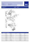
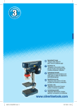
BDP500-16LA FR NL GB PERCEUSE A COLONNE KOLOMBOORMACHINE DRILL PRESS 2009 1 A 2 3 4 5 FR –PERCEUSE A COLONNE MISE EN GARDE pourraient toucher la perceuse si la pièce Pour votre propre sécurité, lisez préalablement bougeait de manière inattendue. ce manuel d’utilisation avant d’utiliser la _ N’utilisez machine. complètement montée et installée pas la machine avant qu’elle ait été conformément aux instructions. CONSIGNES DE SÉCURITÉ _ N’allumez pas la machine tout en bougeant la Lors d’emploi de la machine, observez toujours tête relative à la table ou vice versa. N’allumez scrupuleusement les consignes de sécurité pas la machine avant d’avoir vérifié que la tête fournies ainsi que les consignes de sécurité et la table ont été fermement fixées au support. complémentaires ci-dessous. _ N’utilisez pas la machine si une pièce est endommagée ou fonctionne mal. Dans ce manuel sont employés les _ Réglez la table ou la butée de profondeur pictogrammes suivants : pour éviter que la perceuse n’entre dans la table. N’effectuez aucune activité de Risque de lésion corporelle ou de dégâts matériels. conception, d’assemblage ou de construction sur la table alors que la machine fonctionne. _ Veillez La machine est munie des pictogrammes à ce que la clé de mandrin (si elle existe) a été retirée avant d’allumer la machine. suivants : _ Avant d’allumer la machine, veillez à ce que le mandrin ait été correctement monté, que le Attention au rayon laser foret de perçage ait été installé fermement dans le mandrin et que le dispositif de sécurité Caractéristiques du rayon laser ait été fermé. _ En INSTRUCTIONS DE SECURITE et le matériel. SUPPLEMENTAIRES POUR _ Eteignez LES PERCEUSES A COLONNE _ Connectez _ Verrouillez arborescence. CONSIGNES DE SÉCURITÉ toujours des lunettes de protection et COMPLÉMENTAIRES POUR LASERS couvrez-vous la tête avec un filet si vous avez _ Mise les cheveux longs. en garde : Le rayon laser est susceptible de provoquer des blessures portez pas de gants, de cravates ou de oculaires. Ne regardez jamais directement vêtements amples. _ Pendant l’interrupteur marche / arrêt lorsque vous quittez la machine. uniquement des rallonges avec un noyau en _ Ne le courant, enlevez le foret et nettoyez la table avant de quitter la machine. uniquement la machine à une alimentation secteur de terre. Utilisez _ Portez cours de fonctionnement, utilisez la vitesse recommandée pour les accessoires de perçage dans le rayon laser. que vous percez, ne tenez jamais la _ Pendant pièce à la main, mais fixez-la fermement à la l’utilisation, ne pointez pas le rayon laser en direction des personnes, directement table de perçage à l’aide d’un étau par ex. Ne ou indirectement au travers de matières laissez jamais vos doigts à un endroit où ils réfléchissantes. 6 _ Ce Si des pièces sont manquantes, n’assemblez pas la machine, ne la branchez pas et ne l’allumez pas avant que les pièces manquantes aient été montées conformément aux instructions. laser est conforme à la classe 2 de la norme EN 60825-1/A11, 1996. Cet appareil ne contient pas de pièces nécessitant une maintenance. N’ouvrez le boîtier sous aucun prétexte. Si l’appareil est endommagé, faites-le réparer par un technicien autorisé. Vérifiez avant utilisation : SÉCURITÉ ÉLECTRIQUE Vérifiez si le voltage mentionné sur la plaque signalétique de la machine correspond bien à la tension de secteur présente sur lieu. _ que la table peut être déplacée en douceur ; _ que le monteur foret peut être monté et descendu en douceur ; _ que la machine ne vibre pas lorsqu’elle est allumée. DESCRIPTION (fig. A) Votre perceuse à colonne a été conçue pour Montage du support (fig. B1) percer des trous dans le bois, le métal et le Installez le pied (11) sur une surface solide et plastique. plane. 1 Bouton marche/arrêt _ Faites 2 Carcasse du moteur glisser le pied par-dessus le pilier (12) selon l’orientation illustrée. 3 Support _ Montez le pilier à l’aide des fixations (13). 4 Stockage 5 Table Montage de la table (fig. B2) 6 Mandrin _ Faites 7 Dispositif de sécurité _ Serrez glisser la table (5) sur le pilier (12). la poignée de blocage (14). 8 Monteur foret 9 Butée de profondeur Montage de la tête (fig. B3 & B4) 10 Interrupteur marche/arrêt du laser Montage de la machine _ Montez la table. _ Montez la tête. _ Montez le dispositif de sécurité. _ Montez le mandrin. _ Enlevez _ Serrez fermement les vis Allen (16) pour _ Placez l’ordre indiqué, pour assembler la machine. le support. la tête (15) par-dessus le pilier (12). maintenir la tête en place. Utilisez toujours la procédure suivante, dans _ Montez _ Placez la roue de réglage en hauteur (17) sur l’axe (18) et serrez la vis (19). _ Vissez les boutons (20) sur la roue. Montage du dispositif de sécurité (fig. B5) _ Montez le dispositif de sécurité (7) sur le collier (21). l’huile anti-corrosion sur les parties _ Bloquez métalliques non couvertes à l’aide d’un chiffon le dispositif de sécurité en serrant la vis de serrage (22). et d’un peu d’huile de paraffine. Procédez ensuite au graissage des pièces Montage du mandrin (fig. B6) avec l’huile de lubrification de la machine. _ Ouvrez _ Faites le dispositif de sécurité (7). glisser le mandrin (6) sur la fusée de l’entraînement (23). 7 Insertion et retrait d’un foret (fig. C) _ Utilisez un morceau de bois servant d’appui _ Ouvrez le dispositif de sécurité (7). pour réduire le risque d’éclatement de la pièce _ Ouvrez le mandrin (6). et pour protéger la pointe de la perceuse. _ Insérez le foret dans le mandrin. _ Placez des pièces plates sur un support en _ Serrez le mandrin à la main. bois et fixez-les fermement à la table pour les _ Serrez le mandrin fermement en insérant la empêcher de tourner. Soutenez les pièces qui clé de mandrin dans l’un des trous sur le côté ont une forme irrégulière et qui ne peuvent pas du mandrin et en tournant dans le sens des être mises à plat sur la table. aiguilles d’une montre. _ Utilisez _ Fermez abaisser le monteur foret. Introduisez _ Pour le dispositif de sécurité. les poignées de soulèvement pour doucement la perceuse dans la pièce. retirer un foret, procédez en sens inverse. _ Percez doucement lorsque la perceuse est sur le point de percer la pièce pour éviter de la Avant d’insérer ou de retirer un foret, débranchez toujours la machine e la prise murale. briser en éclat. Mise en marche et arrêt (fig. A) _ Pour mettre la machine en marche, positionnez le bouton marche/arrêt (1) sur ‘I’. Eteignez la machine et attendez qu’elle se soit complètement arrêtée pour changer la vitesse. _ Pour le bouton marche/arrêt (1) sur ‘0’. Utilisation du laser (fig. H) Réglez la vitesse en fonction du matériau à Le faisceau laser sert à indiquer l’emplacement percer et du diamètre de perçage. _ Pour de centrage de l’orifice de perçage, s’il vous percer dans le bois, choisissez une faut percer plusieurs orifices dans des pièces à vitesse élevée. _ Pour ouvrer de la même épaisseur. percer dans le métal et le plastique, _ Placez choisissez une vitesse moins importante plus le _ Placez la pièce à ouvrer sur la table. _ Abaissez des déchets pour vous entraîner et le foret de perçage pour qu’il touche la pièce à ouvrer. apprendre d’abord à utiliser la machine. _ Allumez vous percez, réglez la table afin de le laser (33) en appuyant sur l’interrupteur marche/arrêt (10). faire en sorte que la perceuse soit alignée avec _ Vérifiez l’ouverture au centre de la table. l’alignement du réticule du laser (34) avec le centre de l’orifice de perçage marqué Si nécessaire, marquez la position sur le côté sur la pièce à ouvrer. avant de la colonne et de la table au cas la Si nécessaire, réglez le laser manuellement. table devrait être réglée à la même position _ Suivez plus tard. _ Fixez que le foret et l’ouverture de la table sont alignés. Instructions d’emploi _ Lorsque la table (5) à l’horizontale. _ Assurez-vous diamètre de perçage augmente. _ Utilisez mettre la machine en arrêt, positionnez les «Instructions d’emploi» pour percer. bien la pièce. Le fait de la basculer, de _ Après la tourner ou de la faire glisser n’entraîne pas seulement un mauvais perçage, cela augmente également le risque de casser la perceuse. 8 utilisation, éteignez le laser. NETTOYAGE ET ENTRETIEN La machine n’exige pas d’entretien particulier. _ Nettoyez régulièrement les orifices d’aération. Lubrification _ Mettez la perceuse sur la profondeur de perçage maximum une fois tous les 3 mois et graissez-la légèrement avec de l’huile. SPÉCIFICATIONS TECHNIQUES Tension du réseau V 230 Fréquence du réseau Hz 50 Puissance W 500 Vitesse à vide min-1 280-2.350 Nombre de vitesses de perçage 9 Capacité du mandrin mm 3-16 Dimensions de la tablette mm 170 x 170 Hauteur de la colonne mm 610 Poids kg 19 Niveau de la pression sonore mesuré sur le lieu de travail conformément à la norme EN 61029-1 : LpA (pression sonore) dB(A) < 70 GARANTIE Pour les clauses de garantie, reportez-vous aux conditions de garantie ci-jointes. ENVIRONNEMENT Si, après un certain temps, vous décidez de remplacer votre machine, ne vous en débarrassez pas avec les ordures ménagères mais destinez-la à un traitement respectueux de l’environnement. Fabriqué en Chine 9 2009 NL - KOLOMBOORMACHINE WAARSCHUWING plaats waar ze in aanraking kunnen komen met Lees voor uw eigen veiligheid deze de boor als het werkstuk onverwachts gebruiksaanwijzing goed door alvorens de verschuift. machine te gebruiken. _ Gebruik de machine niet voordat deze volledig volgens de instructies is gemonteerd VEILIGHEIDSVOORSCHRIFTEN en geïnstalleerd. Volg bij gebruik van de machine altijd de _ Schakel de machine niet in terwijl u de kop of bijgeleverde veiligheidsvoorschriften en de tafel ten opzichte van elkaar verplaatst. onderstaande aanvullende Schakel de machine niet in voordat u veiligheidsvoorschriften nauwkeurig op. gecontroleerd heeft of de kop en tafel stevig aan de kolom gemonteerd zijn. In deze handleiding worden de volgende _ Gebruik de machine niet als een onderdeel pictogrammen gebruikt: slecht functioneert of beschadigd is. _ Stel de tafel of diepteaanslag zodanig in dat u niet in de tafel kunt boren. Gevaar voor lichamelijk letsel of materiële schade. _ Verricht geen ontwerp-, montage- of opbouwwerkzaamheden op de tafel terwijl de machine is ingeschakeld. Op de machine vindt u de volgende _ Controleer of de boorhoudersleutel (indien pictogrammen: van toepassing) uit de boorhouder is verwijderd voordat u de machine inschakelt. Waarschuwing voor laserstraal _ Zorg voordat u de machine inschakelt dat de boorhouder correct is aangebracht, de boor stevig in de boorhouder vastzit en de Eigenschappen van laserstraal beschermkap is dichtgeklapt. _ Hanteer het aanbevolen toerental voor de booraccessoires en voor het materiaal. AANVULLENDE _ Schakel de stroom uit, verwijder de boor en VEILIGHEIDSVOORSCHRIFTEN maak de tafel schoon voordat u bij de machine VOOR KOLOMBOORMACHINES wegloopt. _ Sluit de machine uitsluitend aan op een _ Vergrendel de aan/uit-schakelaar wanneer u geaard stopcontact. de machine achterlaat. Gebruik uitsluitend drieaderige verlengsnoeren. _ Draag altijd een veiligheidsbril, en bij lang AANVULLENDE haar een haarnetje. VEILIGHEIDSVOORSCHRIFTEN VOOR _ Draag geen handschoenen, stropdas of LASERS loshangende kleding. _ Waarschuwing! De laserstraal kan _ Houd tijdens het boren het werkstuk nooit potentieel ernstige schade aan de ogen met de hand vast, maar klem het stevig aan de veroorzaken. Kijk of staar nooit direct in de boortafel vast met behulp van bijvoorbeeld een laserstraal. werkstukklem. Houd uw vingers nooit op een 10 Bouw de machine bij het ontbreken van onderdelen niet op, steek de stekker niet in het stopcontact en schakel de machine niet in tot de ontbrekende onderdelen volgens de instructies zijn gemonteerd. _ Richt de laserstraal tijdens gebruik nooit op mensen, hetzij direct, hetzij indirect via reflecterende oppervlakken. _ Deze laser voldoet aan klasse 2 volgens EN 60825-1/A11, 1996. Het apparaat heeft geen onderhoudsdelen. Open de behuizing in geen geval. Indien het apparaat is beschadigd, laat u de beschadiging repareren door een Controleer voor gebruik: erkend reparateur. _ dat de tafel soepel kan worden bewogen; ELEKTRISCHE VEILIGHEID _ dat de boorhouder soepel op en neer kan Controleer of de op het typeplaatje van de worden bewogen; machine vermelde spanning overeenkomt met _ dat de machine, wanneer ingeschakeld, niet de ter plaatse beschikbare netspanning. trilt. BESCHRIJVING (fig. A) Monteren van het statief (fig. B1) Uw kolomboormachine is ontworpen voor het Installeer de voet (11) op een egaal en stevig boren van gaten in houten, metalen en oppervlak. kunststof werkstukken. _ Schuif de voet over de kolom (12) in de 1 Aan/uit-schakelaar oriëntatie zoals afgebeeld. 2 Motorbehuizing _ Monteer de kolom met behulp van de 3 Statief bevestigingsmiddelen (13). 4 Opberglade 5 Tafel Monteren van de tafel (fig. B2) 6 Boorhouder _ Schuif de tafel (5) over de kolom (12). 7 Beschermkap _ Draai de vergrendelingshendel (14) vast. 8 Boorlift 9 Diepteaanslag Monteren van de kop (fig. B3 & B4) 10 Aan/uit-schakelaar laser _ Plaats de kop (15) op de bovenzijde van de kolom (12). Opbouwen van de machine _ Draai de inbusschroeven (16) vast om de kop Hanteer bij het opbouwen van de machine altijd op zijn plaats te houden. de volgende procedure, in de aangegeven _ Plaats het hoogte-instelwiel (17) op de volgorde: schacht (18) en draai de schroef (19) vast. _ Monteer het statief. _ Schroef de knoppen (20) op het wiel. _ Monteer de tafel. _ Monteer de kop. Monteren van de beschermkap (fig. B5) _ Monteer de beschermkap. _ Monteer de beschermkap (7) op de kraag _ Monteer de boorhouder. (21). _ Verwijder de roestwerende olie op de _ Zet de beschermkap vast door de onbeschermde metalen onderdelen met behulp klemschroef (22) vast te draaien. van een doek en een kleine hoeveelheid parrafineolie. Smeer de onderdelen vervolgens met machinesmeerolie. 11 Monteren van de boorhouder (fig. B6) de voorzijde van de kolom en de tafel, in geval _ Open de beschermkap (7). u de tafel op een later tijdstip opnieuw in de _ Schuif de boorhouder (6) op de aandrijfas middenpositie wilt plaatsen. (23). _ Klem het werkstuk stevig vast. Elke kanteling, draaiing of verschuiving leidt niet alleen tot een Plaatsen en verwijderen van een boor ruw boorgat, maar vergroot ook het risico dat (fig. C) de boor afbreekt. _ Klap de beschermkap (7) open. _ Gebruik een stuk afvalhout als ondergrond. _ Open de boorhouder (6). Dit verkleint de kans op versplinteren van het _ Steek de boor in de boorhouder. werkstuk en beschermt de punt _ Draai de boorhouder met de hand vast. van de boor. _ Draai de boorhouder stevig vast door de _ Leg platte werkstukken op een houten boorhoudersleutel in een van de gaten in de ondergrond en klem ze stevig tegen de tafel zijkant van de boorhouder te steken en aan zodat ze niet kunnen gaan draaien. rechtsom te draaien. Ondersteun werkstukken die onregelmatig van _ Klap de beschermkap dicht. vorm zijn en niet plat op de tafel neergelegd _ Om de boor te verwijderen, gaat u in kunnen worden. omgekeerde volgorde te werk. _ Gebruik de lifthendels om de boorlift naar beneden te brengen. Neem voor het plaatsen of verwijderen van een boor altijd de netstekker uit het stopcontact. Drijf de boor behoedzaam het werkstuk in. _ Boor langzaam wanneer de boor op het punt staat door het werkstuk heen te gaan. Zo voorkomt u dat het ondervlak gaat splinteren. Schakel de machine uit en wacht tot de machine volledig tot stilstand is gekomen, voordat u het toerental verandert. In- en uitschakelen (fig. A) _ Om de machine in te schakelen, zet u de aan/uit-schakelaar (1) op ‘I’. Stel het toerental in naar het te boren materiaal _ Om de machine uit te schakelen, zet u de en de boordiameter. aan/uit-schakelaar (1) op ‘’0'. _ Kies een hoog toerental voor het boren in hout. Gebruiken van de laser (fig. H) _ Kies voor het boren in metaal en kunststoffen De lasterstraal wordt gebruikt om het centrum een lager toerental wanneer de boordiameter van het boorgat aan het geven in het geval dat toeneemt. u verschillende gaten van dezelfde dikte in werkstukken moet boren. Aanwijzingen voor gebruik _ Plaats de tafel (5) in een horizontale positie. _ Gebruik eerst afvalmateriaal om uw _ Zorg ervoor dat de boor en de opening in de vaardigheid te oefenen en de machine te leren tafel op een lijn zijn. beheersen. _ Plaats het werkstuk op de tafel. _ Stel bij volledige doorboring de tafel zodanig _ Breng de boor naar beneden totdat hij het op dat de boor in de middenopening uitkomt. werkstuk raakt. Markeer deze positie eventueel op _ Schakel de laser (33) aan door de aan/uit-schakelaar (10) te bedienen. 12 _ Controleer of het dradenkruis (34) op een lijn is met het centrum van het boorgat zoals GARANTIE gemarkeerd op het werkstuk. Voor de garantiebepalingen wordt verwezen Stel de laser indien noodzakelijk met de hand naar de bijgevoegde garantievoorwaarden. af. _ Volg de “Aanwijzingen voor gebruik” om een MILIEU Als uw machine na verloop van tijd aan vervanging toe is, geef hem dan niet met het huisvuil mee, maar zorg voor een milieuvriendelijke verwerking. boorgat te maken. _ Schakel na gebruik de laser uit. REINIGING EN ONDERHOUD De machine vergt geen speciaal onderhoud. _ Reinig regelmatig de ventilatieopeningen. Smering _ Draai de boorspil eenmaal in de 3 maanden tot de maximale diepte naar beneden en smeer hem lichtjes met olie in. TECHNISCHE GEGEVENS Netspanning V 230 Netfrequentie Hz 50 Vermogen W 500 Toerental (onbelast) min-1 280-2.350 Aantal boorsnelheden 9 Boorhoudercapaciteit mm 3-16 Afmetingen tafelblad mm 170 x 170 Kolomhoogte mm 610 Gewicht kg 19 Niveau van de geluidsdruk op de werkplek gemeten volgens EN 61029-1: LpA (geluidsdruk) dB(A) < 70 Made in China 13 2009 GB - DRILL PRESS WARNING not switch on the machine until having checked Read this manual carefully before using the that head and table have been tightened firmly machine, for your own safety. to the pillar. Do not use the machine if a part is damaged SAFETY INSTRUCTIONS or badly functioning. When using the machine, always observe the Adjust the table or depth stop to prevent the enclosed safety instructions as well as the drill from entering the table. Do not perform any additional safety instructions. design, assembly or construction activities on the table while the machine is switched on. The following symbols are used throughout this Make sure that the chuck key (if applicable) manual: has been removed before switching on the machine. Denotes risk of personal injury or damage to the tool. Before switching on the machine, make sure the chuck has been mounted correctly, the drill has been mounted into the chuck firmly and the You will find the following symbols on the safety guard has been shut. machine: In operation, use the recommended speed for the drilling accessories and the material. Switch off the power, remove the drill and Laser beam warning clean the table before leaving the machine. Lock the on/off switch when leaving the machine. Laser beam characteristics ADDITIONAL SAFETY INSTRUCTIONS FOR ADDITIONAL SAFETY INSTRUCTIONS FOR LASERS DRILL PRESSES Warning! The laser beam potentially causes Only connect the machine to an earthed severe eye damage. Never look or stare mains supply. directly into the laser beam. Only use tree-core extension cords. During use, do not point the laser beam at Always wear safety goggles, and a hairnet people, directly or indirectly through reflecting for long hair. surfaces. Do not wear gloves, ties or loose clothing. This laser complies with class 2 according to While drilling, never hold the workpiece by EN 60825-1/A11, 1996. The unit includes no hand, but firmly tighten it to the drilling table servicing components. Do not open the using a vice e.g. Never keep your fingers on a housing for any reason. If the unit is damaged, place where they could touch the drill in case have the damage repaired by an authorized the workpiece should move unexpectedly. repair agent. Do not use the machine until it has been mounted and installed completely according to ELECTRICAL SAFETY Always check that the power supply corresponds to the voltage on the rating plate. the instructions. Do not switch on the machine while moving the head relative to the table or vice versa. Do 14 DESCRIPTION (fig. A) Mounting the stand (fig. B1) Your drill press has been designed for drilling Install the foot (11) on a level and solid surface. holes in wood, _ Slide the foot over the pillar (12) in the metal and plastics. orientation as shown. 1 On/off switch _ Mount the pillar using the fasteners (13). 2 Motor housing 3 Stand Mounting the table (fig. B2) 4 Storage _ Slide the table (5) over the pillar (12). 5 Table _ Tighten the locking handle (14). 6 Chuck 7 Safety guard Mounting the head (fig. B3 & B4) 8 Drill lift _ Place the head (15) on the top of the pillar 9 Depth stop (12). 10 Laser on/off switch _ Firmly tighten the Allen screws (16) to keep the head in place. Assembling the machine _ Place the height adjustment wheel (17) onto Always use the following procedure, in the the shaft (18) and tighten the screw (19). order given, when assembling the machine. _ Screw the knobs (20) onto the wheel. Mount the stand. Mount the table. Mounting the safety guard (fig. B5) Mount the head. _ Mount the safety guard (7) onto the collar Mount the safety guard. (21). Mount the chuck. _ Secure the guard by tightening the clamp Remove the anti-corrosive oil on the screw (22). uncovered metal parts using a cloth and a little parrafin oil. Proceed with greasing the parts Mounting the chuck (fig. B6) with machine lubricating oil. _ Open the safety guard (7). _ Slide the chuck (6) onto the drive spindle If parts are missing, do not assemble the machine, do not plug in and do not switch on the machine until the missing parts have been mounted according to the instructions. (23). Inserting and removing a drill (fig. C) _ Open the safety guard (7). _ Open the chuck (6). _ Insert the drill into the chuck. _ Fasten the chuck by hand. _ Fasten the chuck firmly by inserting the chuck Check before operation: key in one of the holes in the side of the chuck and turning it clockwise. _ that the table can be moved smoothly; _ Shut the safety guard. _ that the drill lift can be moved up and down _ In order to remove a drill, proceed in reverse smoothly; order. _ that the machine does not shake when it is switched on. Before inserting or removing a drill, always pull the plug from the wall socket. 15 Switch off the machine and wait until the machine has come to a complete standstill before changing the speed. The laser beam is used to indicate the centre location of the drill hole in case you have to drill several holes in workpieces of the same thickness. _ Place the table (5) in a horizontal position. Adjust the speed to the material to be drilled _ Make sure that the drill and the opening in and the drilling diameter. the table are aligned. _ For drilling in wood, choose a high speed. _ Place the workpiece on the table. _ For drilling in metal and plastics, choose a _ Lower the drill bit until it touches the lower speed as the drilling diameter increases. workpiece. _ Switch the laser (33) on by operating the Instructions for use on/off switch (10). _ Use waste material to practise your skills and _ Check that the laser cross hairs (34) align to learn operating the machine first. with the centre of the drill hole as marked on _ When drilling through, adjust the table to the workpiece. If necessary, adjust make sure that the drill is alligned with the the laser by hand. opening in the centre of the table. _ Follow the “Instructions for use” to perform a If required, mark the position on the front side drill hole. of pillar and table in case the table should be _ After use, switch off the laser. set in the same position at a later time. _ Securely tighten the workpiece. Toppling, CLEANING AND MAINTENANCE turning or sliding not only results in a rough The machine does not require any special drilling hole, it also increases the risk of the drill maintenance. breaking off. _ Regularly clean the ventilation slots. _ Use a piece of waste wood as a backup to reduce the risk of the workpiece splintering and Lubrication to protect the drill tip. _ Turn the drill shaft to the maximum drilling _ Place flat workpieces on a wooden depth once per 3 months and grease it slightly underground and clamp securely to the table to with oil. prevent them from turning. Support workpieces that are irregular of shape and cannot be put TECHNICAL DATA flat onto the table. _ Use the lift handles to bring the drill lift downwards. Slowly feed the dril into the workpiece. _ Drill slowly when the drill is about to break through the workpiece to prevent splintering. Switching on and off (fig. A) _ To switch the machine on, set the on/off switch (1) to ‘I’. _ To switch the machine off, set the on/off Mains voltage V 230 Mains frequency Hz 50 Power input W 500 No-load speed min-1 280-2,350 Number of drilling speeds 9 Chuck capacity mm 3-16 Table dimensions mm 170 x 170 Pillar height mm 610 Weight kg 19 Level of sound pressure measured according switch (1) to ‘0’. to EN 61029-1: LpA (sound pressure) dB(A) Using the laser (fig. H) 16 < 70 GUARANTEE Refer to the enclosed guarantee conditions for the terms and conditions of guarantee. ENVIRONMENT Should your machine need replacement after extended use, do not put it in the domestic waste but dispose of it in an environmentally safe way. Made in China 17 2009 81, rue de Gozée 6110 Montigny-le-Tilleul Belgique Tél : 0032 71 29 70 70 Fax : 0032 71 29 70 86 Made in China S.A.V 32 / 71 / 29 . 70 . 88 32 / 71 / 29 . 70 . 99 Service Parts separated 32 / 71 / 29 . 70 . 83 32 / 71 / 29 . 70 . 86 2009 Made in China 18