1
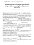
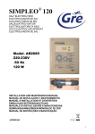
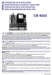
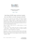
ISTRUZIONI PER USO ED INSTALLAZIONE
INSTRUCTIONS POUR L’UTILISATION ET L’INSTALLATION
OPERATING AND INSTALLATION INSTRUCTIONS
GEBRAUCHSANWEISUNGEN UND INSTALLATION
TX
FTC
920/960
RX
La ditta FERPORT S.a.s. non risponde per errati collegamenti e/o manomissioni delle centrali e tantomeno le riterrà in garanzia.
La ditta FERPORT S.a.s. precisa di aver depositato il Mod. FTC 920/960. Il medesimo sarà quindi tutelato in tutte le sue parti a norma di
legge. Nessuna parte del contenuto di questo manuale può essere riprodotta senza autorizzazione scritta della FERPORT S.a.s.
I collegamenti alla centrale devono essere eseguiti solo da personale specializzato e dopo aver attentamente letto le istruzioni sopra riportate.
N.B.: E’ richiesto l’inserimento di un interruttore onnipolare presso la centrale, con distanza di apertura minima dei contatti di 3 mm, per lo spegnimento
della stessa prima dell’apertura per manutenzione (CEI 64-8).
I
La maison FERPORT S.a.s. dégage toute responsabilité en cas de mauvaises connexions et/ou endommagement des unités. En pareil cas
la garantie n’est pas valable.
La maison FERPORT S.a.s.a déposé le Modèle FTC 920/960. Toute pièce composant cette unité sera donc protégée d'après les normes en vigueur.
Aucune partie de ce manuel d’utilisation ne peut être reproduite sans l’autorisation écrite de FERPORT S.a.s.
Les connexions à l’unité ne seront effectuées que par des techniciens qualifiés et après avoir attentivement lu les instructions ci-dessus.
ATTENTION! Il est nécessaire d’équiper l’unité d’un interrupteur omnipolaire, avent une distance d’ouverture minimum des contacts de 3 mm. ce qui permet la mise hors service de celle-ci avant l’ouverture lors des opérations l’entretien (CEI 64-8).
F
FERPORT S.a.s. is not liable for damages due to incorrect connections and/or tampering of the receivers neither are such damages covGB ered
by guarantee.
Model FTC 920/960 is a registered trademark of FERPORT S.a.s. Such devices and all its parts are protected according to the existing laws.
No part of this guide may be reproduced without the prior written permission of FERPORT S.a.s.
The connections to the terminal board are to be carried out by qualified people after having read the above mentioned instructions.
NB: An omnipolar switch is required in the terminal with contacts having a minimum distance of 3 mm, in order to switch it off before servicing (CEI
64-8).
Die Firma FERPORT S.a.s. steht nicht für falsche Verbindungen und/oder Verletzungen der Steuereinheiten ein und wird sie auf jeden Fall nicht
in der Garantie einbeziehen.
Die Firma FERPORT S.a.s. gibt genau an, dass sie das Modell FTC 920/960 hat patentieren lassen. Dieselbe Steuereinheit und all ihre Teile werden deswegen auf Grund des Gesetzes geschützt. Man darf kein Teil dieses Handbuchs ohne die schriftliche Genehmigung der Firma FERPORT S.a.s.
vervielfältigen.
Die Anschlüsse an die Steuereinheit müssen nur von Fachleuten ausgeführt werden, nachdem sie die obengenannten Anweisungen aufmerksam
gelesen haben.
NB: Man braucht, einen allpoligen Schalter an die Steuereinheit mit mindestem Öffnungsabstand zwischen den Kontakten von 3 mm einzusetzen, der die
Steuereinheit vor der Instandhaltungsöffnung ausschaltet. (CEI 64-8)
D
1
Rev. 001 09/03
FOTOCELLULA RX
RX 960
ITALIANO
RX 920
SENSORE IR
SENSORE IR
LED SEGNALAZIONE
ALLINEAMENTO
J1
1
1
2
3
2
3
4
Alimentazione 12V dc/24V ac/dc Alimentazione 12V dc/24V ac/dc +
Comune
5
4 nc
5 na
J1 Ponticello aperto 24V
Ponticello chiuso 12V
FOTOCELLULA TX
TX 920
TX 960
22,5 mm
TRASMETTITORE IR
TRASMETTITORE IR
82 mm
LED SEGNALAZIONE
ALIMENTAZIONE
LED SEGNALAZIONE
ALIMENTAZIONE
J1
J1
46,5 mm
1
2
2
1
2
Alimentazione 12V dc/24V ac/dc Alimentazione 12V dc/24V ac/dc +
- Alimentazione 12 ac/24V ac/dc
- Assorbimento: 108mA a 24V ac
- Led di segnalazione allineamento sul ricevitore
- Led di segnalazione di alimentazione sul trasmettitore
- Resistenze antiappannamento nel TX e nel RX (solo nella versione 24V)
- Distanza massima di funzionamento
FTC920 20 mt.
FTC960 60 mt
- Emissione all’infrarosso con modulazione continua: 1,33 Khz
- Lunghezza d’onda dell’emissione: 950 nM
- Massima potenza commutabile 1A a 24Vac
- Grado protezione IP55
ISTRUZIONI MONTAGGIO
E TARATURA
Fissare i contenitori esterni sui pilastri o sulle colonnine ad un’altezza di circa 40-60 cm dal suolo e a una distanza max di 10 cm
dalla zona di convogliamento o schiacciamento, o subito dopo l’ingombro dato da un’eventuale costa. Nel caso di ante su cancelli a battente la distanza di 10 cm è da misurare nella posizione delle ante aperte (NORMATIVE UNI8612).
Le fotocellule sono autocentranti, si consiglia però per un più corretto funzionamento di posizionarle sullo stesso asse.
ISTRUZIONI MONTAGGIO GUARNIZIONI
E PRESSACAVO
Alloggiare la guarnizione in gomma (OR) nella canalina del vetrino della fotocellula in modo da far capitare la giuntura della stessa nel lato orizzontale alto del vetrino, assicurarsi che i due capi della guarnizione sormontino di almeno 15 mm.
A questo punto è possibile tramite pressione chiudere i due semigusci.
Il passaggio del cavo dovrà avvenire dopo aver praticato un foro di diametro leggermente inferiore del cavo utilizzato sul tappo di
chiusura del foro posteriore.
N.B.: Frontale lente per ricevitore
Frontale senza lente per trasmettitore
3
ITALIANO
SPECIFICHE TECNICHE
SCHEMA DI INSTALLAZIONE
ITALIANO
FISSAGGIO A COLONNA
3
1
2
3 4
FISSAGGIO CON AD 90
3
1
2
FISSAGGIO A INCASTRO CON SMA 2P
3
1
2
3 4
3
5
FISSAGGIO CON AD 60
AD 60
CH 1
1)
2)
3)
4)
5)
O-ring
Elettronica
Contenitore
Guarnizione di tenuta in gomma
O-ring
CH1 Chiave per smontaggio vetrino frontale
4
SM 1
AD 90
FOTOCELLULE RX
RX 920
RX 960
RECEPTEUR IR
FRANÇAISE
RECEPTEUR IR
LED SIGNALISATION
D’ALIGNEMENT
J1
1
1
2
3
2
3
4
5
4 Normalement fermé
5 Normalement ouvert
J1 Embroche ouvert 24V
Embroche fermé 12V
Alimentation 12V dc/24V ac/dc Alimentation 12V dc/24V ac/dc +
Commun
FOTOCELLULE TX
TX 920
TX 960
22,5 mm
EMETTEUR IR
EMETTEUR IR
82 mm
LED SIGNALISATION
D’ALIMENTATION
LED SIGNALISATION
D’ALIMENTATION
J1
J1
46,5 mm
1
1
2
2
5
Alimentation 12V dc/24V ac/dc Alimentation 12V dc/24V ac/dc +
FRANÇAISE
SPECIFICATIONS TECHNIQUES
- Alimentations 12/V ac/24V ac/dc
- Absorption: 108mA a 24V ac
- Led de signalisation d’alignement sur le récepteur
- Led de signalisation d’alimentation sur l’émetteur
- Résistance antibuée, (anti-embeument dans le TX et le RX, seulement dans la version 24V)
- Distance maxi de fonctionnement (dans les conditions optimales):
20 métrés-modèle FTC920
60 métrés-modèle FTC960
- Emission à l’infrarouge avec modulation continue: 1,33 Khz
- Longueur d’onde de l’émission: 950 nM
- Puissance maximale 1A a 24V ac
- Degré de protection IP55
INSTRUCTION DE MONTAGE
ET DE TARAGE
Fixer les boitiers extérieures sur des piliers ou sur des petites colonnes a une hauteur d’environ 40 à 60 cm du sol, d’une distance maximum de 10 cm de la zone d’acheminement ou d’écrasement ou bien immédiatement après l’encombrement donné d’une
éventuelle cote. Si on a des volets sur des grilles battant-tes, il faut mesurer une distance de 10 cm avec les volets ouvert (NORME
UNI 8612).
Les cellules photo-électriques sont auto-concentrantes, mais pour mieux les utiliser, on conseille de les mettre sur le même axe.
INSTRUCTIONS SUR LE MONTAGE DES
OINTS ET DU PASSE-CABLE
Introduire l’anneau torique d’étanchéité (O-ring) dans le caniveau du petit verre de la photocéllule de façon que la jointure de celleci adhère au cote horizontal du petit verre. Contrôler à ce que les extrémités de l’anneau torique d’étanchéité dépassent d’au moins
15 mm.
Maintenant il est possible de fermer par pression les deux semi-coquilles.
Le passe du cable se réalise après avoir effectué un trou, au diamètre légèrement inférieur par rapport au cable utilisé, sur le bouchon de fermeture du trou arrière.
N.B.: Devant avec lentille pour récepteur
Devant sans lentille pour émetteur
6
PLAN D’INSTALLATION
FIXATION A COLONNE
1
2
3 4
FRANÇAISE
3
FIXATION PAR AD 90
3
1
2
FIXATION A EMBOITEMENT PAR SMA 2P
3
1
2
3 4
3
5
FIXATION PAR AD 60
AD 60
CH 1
1)
2)
3)
4)
5)
Anneau torique d’étanchéité (O-ring)
Partie électronique
Conteneur
Joint d’étanchéité en caoutchouc
O-ring
CH1 Clé pour démontage du petit verre frontal
7
SM 1
AD 90
PHOTOCELLE RX
RX 920
RX 960
SENSOR IR
SENSOR IR
POSITIONING SIGNAL LED
J1
ENGLISH
1
1
2
3
2
3
4
5
4 nc
5 no
J1 24V open connection
12V closed connection
12V dc/24V ac/dc - feeding
12V dc/24V ac/dc + feeding
Common contact
PHOTOCELLE TX
TX 920
TX 960
22,5 mm
TRANSMITTER IR
TRANSMITTER IR
82 mm
POSITIONING
SIGNAL LED
POSITIONING
SIGNAL LED
J1
J1
46,5 mm
1
2
8
1
2
12V dc/24V ac/dc - feeding
12V dc/24V ac/dc + feeding
TECHNICAL SPECIFICATIONS
- 12/V ac/24V ac/dc feeding
- Absorption: 108mA a 24V ac
- Positioning signal led on receiver
- Feeding signal led on receiver
- Condense resistance on TX and RX
20 mts. maximum working distance (Mod. FTC920) optimal condition
60 mts. maximum working distance (Mod. FTC960)
- Infrared emission with constant modulation: 1,33 Khz
- Emission wavelength: 950 nM
- Max power commutable 1A a 24V ac
- IP55 Protection degree
Fix the external shells of the photo-cells on the concrete wall or on the metallic support. The distance from the ground must be
about 40-60 cm and 10 cm maximum from the external line of the gate.
The correct distance in other case referred to photo-cells installed on leaf gates must be measured from the open position or after
mechanical strips.
Photo-cells are centering by thernselves.
We suggest to install them on the same axis, to obtain a correct working without mistakes.
GASKET AND PRESSWIRE INSTRUCTION
OF ASSEMBLY
Install the o-ring gasket in the wire support on the sight photo-cell, control the right orizont al position on the upper side of the sight.
Assure the two side of the gasket up to 15 mm on the both faces.
After this operation press the two shells towards themselves and control the perfect closing line before installing the electrical wire
inside of the box of photo-cell, a smaller hole with thin diameter respect to the electric wire.
Will be drilled on the back cap.
General warnings: only authorised and good trained personal may operate on our plants.
N.B. Front with receiver lens
Front without transmitter lens.
9
ENGLISH
SETTING AND
ADJUSTING INSTRUCTION
INSTALLATION DIAGRAM
COLUMN MOUNT
3
1
2
3 4
MOUNT WITH AD 90
1
2
ENGLISH
3
JOINT MOUNT
3
1
2
3 4
3
5
MOUNT WITH AD 60
AD 60
CH 1
1)
2)
3)
4)
5)
O-ring
Electronics
Container
Rubber seal
O-ring
CH1 Key for removing the front glass
10
SM 1
AD 90
FOTOZELLE RX
RX 920
RX 960
SENSOR IR
SENSOR IR
SIGNALLEUCHTE ANGLEICHEN
J1
1
1
2
3
2
3
4
5
4 N.G.
5 N.O.
J1 Brücke geöffnet 24V
Brücke geschlossen 12V
Stromversorgung 12V dc/24V ac/dc –
Stromversorgung 12V dc/24V ac/dc +
Gemeinsame Erdungskontakte
TX 920
TX 960
22,5 mm
SENDER IR
SENDER IR
82 mm
SIGNALLEUCHTE
STROMVERSORGUNG
SIGNALLEUCHTE
STROMVERSORGUNG
J1
J1
46,5 mm
1
2
11
1
2
Stromversorgung 12V dc/24V ac/dc –
Stromversorgung 12V dc/24V ac/dc +
DEUTSCH
FOTOZELLE TX
TECHNISCHE DATEN
- Stromversorgung 12V dc/24V ac/dc
- Absorption: 108mA a 24V ac
- Signalleuchte Angleichen auf dem Empfänger
- Signalleuc hte Stromversorgung auf dem Sender
- Anti-Beschlag-Widerstand im TX und RX
- 20 mt füer modelle FTC920
- 60 mt füer modelle FTC960
- Infrarotstrahlung mit Endlosmodulation: 1,33 Khz
- Wellenläge 950 nM
- Maximale umschaltbare Höchstleistung 1A a 24V ac
- Schutzgrad IP55
MONTAGEANLEITUNGEN FÜR
MONTAGE UND EINSTELLUNG
DEUTSCH
Die äusseren Behälter in einer Höhe von ca. 40-60 cm vom Boden an einer Säule oder einem Ständer in einer Entfernung von
maximal 10 cm vom Förderungsbereich oder einer Leiste befestigen. Im Falle von Schwingtüren ist die Entfernung von 10 cm von
der geöffneten Tür an zu messen (Vorschriften UNI18612).
Die Fotozellen sind sebstzentrierend, es ist für einen korrekten Betrieb ratsam, sie auf derselben Achse zu positionieren
MONTAGEANLEITUNGEN DICHTUNGEN
UND KABELPRESSEN
Die Gummidichtung (OR ) mit der der Glasrille der Fotozelle anbringen, mit der Verbindungsnaht an der oberen Seite des Glases,
sicherstellen, daß die beiden Enden der Dichtung 15 cm überstehen.
Danach mit leichtem Druck die beiden Halbschalen andrücken und schließen.
Das Durchführen des Kabels erfolgt, nachdem ein Loch am Deckel gebohrt wurde, das einen etwas kleineren Durchmesser hat als
das des Kabels am Deckel des hinteren Loches.
ANM.: Vorderseite mit Glas für den Empfänger
Vorderseite ohne Glas für den Empfänger
12
INSTALLIERUNGSSCHEMA
BEFESTIGUNG AN SÄULE
3
1
2
3 4
BEFESTIGUNG MIT AD 90
3
1
2
EINSPANNUNGSBEFESTIGUNG MIT SMA 2P
1
2
3 4
3
5
BEFESTIGUNG MIT AD 60
AD 60
CH 1
1)
2)
3)
4)
5)
O-Ring
Elektronik
Behälter
Gummidichtung
O-Ring
CH1 Schlüssel zur Abnahme des Glases
13
SM 1
AD 90
DEUTSCH
3
STUDIO GRAFICO IMMAGINE (tel. 030.9913938)
Via Chienti, 10 - 20052 Monza (MI) Italy
Tel. +39.039.734095 - Fax +39.039.734951
web site: www.ferport.it - e-mail: [email protected]
16