1
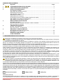
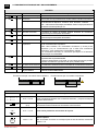
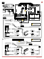
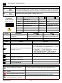
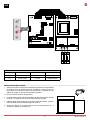
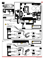
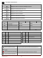
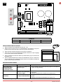
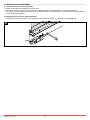
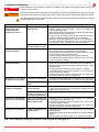
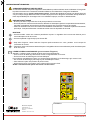
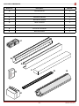
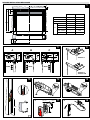
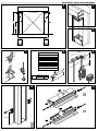
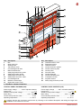
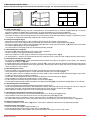
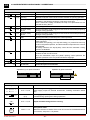
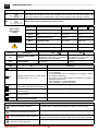
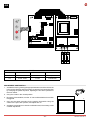
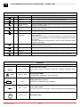
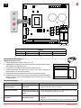
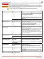
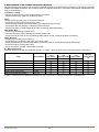
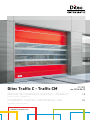
Ditec Traffic C - Traffic CM
0DT829
rev. 2014-06-13
Manuel de installation, entretien, utilisation.
FR
Installation manual, maintenance, use.
EN
(Instructions originales)
(Original instructions)
www.ditecentrematic.com
Sommaire des arguments
Ch.Argument .............................................................................................................................. Page
1.
CONSIGNES GÉNÉRALES DE SÉCURITÉ ................................................................................ 2
2. CARACTÉRISTIQUES TECHNIQUES ........................................................................................ 3
3. INSTALLATION MÉCANIQUE
3.1 Vérifications initiales ............................................................................................................... 4
3.2 Fixation des montants verticaux.............................................................................................. 4
3.3 Montage de la traverse ........................................................................................................... 4
3.4 Préparation de la traverse........................................................................................................ 4
3.5 Montage du tablier................................................................................................................... 4
3.6 Montage des contrepoids ........................................................................................................ 4
3.7 Montage du levier de déverrouillage d'urgence (en option)..................................................... 4
3.8 Installation des cellules photoélectriques ................................................................................ 4
3.9 Installation du bourrelet de sécurité ........................................................................................ 4
4.
BRANCHEMENTS ÉLECTRIQUES
4.1 Tableau électrique.................................................................................................................... 5
4.2 Raccordements du tableau électrique / moteur / sécurités...................................................... 5
4.3 Photocellules de sécurité......................................................................................................... 5
5. TABLEAU ÉLECTRONIQUE
5.1 49E - raccordements................................................................................................................ 6
5.2 47E (inverseur) - raccordements........................................................................................... 10
6.RÉGLAGES ET MISE EN MARCHE
6.1 Vérification des sens du mouvement .................................................................................... 14
6.2 Réglage du bourrelet au ras.................................................................................................. 14
7. RECHERCHE DES PANNES...................................................................................................... 15
8. PLAN D'ENTRETIEN.................................................................................................................. 16
1. CONSIGNES GÉNÉRALES DE SÉCURITÉ
Cette notice d’installation est destinée exclusivement aux professionnel qualifiés.
L’installation, le raccordement électrique et les réglages doivent être effectuée selon les réglés de Bonne Techniques
er respecter la réglementation en vigueur.
Lire attentivement les instructions avant de procéder à l’installation du produit. Une installation erronée peut être source de
danger. Les matériaux de l’emballage (plastique, polystyrène, etc) ne doivent pas être abandonnées dans la nature et ne
doivent pas être laissés à la portée des enfants, car ils sont une source potentielle de danger.
Avant de procéder à l’installation, vérifier l'intégrité du produit. Ne pas installer le produit à proximité de matières explosives:
la présence de gaz ou de vapeurs inflammables représente un grave danger pour la sécurité.
Avant d’installer le automatismes, apporter toutes le modifications structurelles relatives à la réalisation des distances de
sécurité et à la protection ou ségrégation de toutes les zones d’écrasement, de cisaillement, d’entraînement et de danger
en général. Vérifier que la structure existante ait les qualités requises de robustesse et de stabilité.
Le dispositifs de sécurité (photocellule, barres palpe uses, arrêt d’urgence, etc) doivent être installés en tenant compte
des normes et directives en vigueur, des critères de Bonne Technique, de l’emplacement de l’installation, de la logique de
fonctionnement du système et des forces dégagées par la porte ou le portail équipés d’automatismes.
Les dispositifs de sécurité doivent protéger les zones éventuelles d’écrasement, de cisaillement, d’entraînement et de
danger en général, de la porte ou du portail automatisés. Appliquer la signalisation prévue par la réglementation en vigueur
pour localiser les zones dangereuses. Toute installation doit indiquer de façon visible les données d’identification de la porte
ou du portail automatisés.
Avant de procéder au raccordement électrique, s’assurer que les données de la plaquette signalétique correspondent à
celles du réseau d’alimentation électrique. Prévoir sur le réseau d’alimentation un dispositif de coupure omnipolaire avec
une distance d’ouverture des contacts égale ou supérieure à 3 mm. Vérifier qu’en amont de l’installation électrique il y ait
un interrupteur différentiel ainsi qu’une protection contre des surchanges de courant adéquate.
Relier la porte ou le portail automatisés à un système de mise à la terre efficace installé conformément aux normes de sécurité en
vigueur. Le constructeur des automatismes décline toute responsabilité au cas où seraient installés des composants incompatibles
en termes de sécurité et de bon fonctionnement ou dans le cas où seraient apportées des modifications de quelque nature
qu'elles soient sans son autorisation spécifique. En cas de réparation ou de remplacement des produits, des pièces de rechange
originales Entrematic Group AB. Impérativement être utilisées. L’installateur doit fournir tous les renseignements concernant
le fonctionnement automatique, manuel ou de secours de la porte ou du portail automatisés et remettre la notice d’emploi à
l’utilisateur.
Accessoire en option
C
Safety Confort
T
Safety Top
Tous droits réservés
Les informations mentionnées dans ce catalogue ont été contrôlées avec la plus grande attention. Toutefois, nous déclinons
toute responsabilité en cas d’erreurs, omissions ou approximations dépendant d’exigences techniques ou graphiques.
0DT829 2014-06-13
-2-
FR
4
3
2
1
11
5
12
9
21
13
17
15
20
19
6
14
22
16
18
7
8
Rif.
1
2
3
4
5
6
7
8
9
10
11
12
13
25
24
23
10
Description
Caisson
Motoréducteur K10
Arbre d'enroulement
Chaîne de transmission
Tambour de la courroie du contrepoids
Levier manuel de déverrouillage
Profilé en aluminium du bourrelet de sécurité
Profilé en caoutchouc du bourrelet de sécurité
Boîte de raccordement du bourrelet
Câble de raccordement du bourrelet
Courroie du contrepoids
Contrepoids modulaire
Couvercle colonne droite
Rif.
14
15
16
17
18
19
20
21
22
23
24
25
Description
Couvercle colonne gauche
Colonne Droite
Colonne Gauche
Profilés en aluminium du tablier
Tube de renforcement du tablier
Tableau électronique
Cellule photoélectrique LAB4
Courroie de levage du tablier
Fixation de la courroie du tablier
Secteur transparent
Secteur en polyester
Poche du revêtement du bourrelet
2. CARACTÉRISTIQUES TECHNIQUES
TABLEAU ÉLECTRONIQUE TRIPHASÉ (49E)
TABLEAU ÉLECTRONIQUE 47E (INVERSEUR)
Tension d'alimentation ........... 400 V triphasé 50/60 Hz
Absorption ............................................................... 6 A
Alimentation commandes auxiliaire..................24V
Puissance moteur.................................. 0,55 ÷ 1,8 KW
Degré de protection tableau de commande........ IP 55
Température de fonctionnement................. - 5 + 50 °C
Tension d'alimentation ..... 230 V monophasé 50/60 Hz
Absorption ............................................................. 12 A
Alimentation commandes auxiliaire..................24V
Puissance moteur.................................. 0,55 ÷ 1,8 KW
Degré de protection tableau de commande........ IP 55
Température de fonctionnement................. - 5 + 50 °C
Dimensionner correctement la section des conducteurs de ligne en se référant à l'absorption indiquée et en tenant
compte de la longueur et de la mise en œuvre des câbles.
-3-
0DT829 2014-06-13
3. INSTALLATION MÉCANIQUE
Voir dessins relatifs à l'installation mécanique aux pages 22 - 23 (feuille centrale à détacher)
3.1 Vérifications initiales (fig.1)
• Vérifier les dimensions du logement et la correspondance avec les mesures de la porte, en tenant compte des tolérances
nécessaires en cas d'installation pour l'ouverture. Vérifier que les éventuels encombrements existants ne gênent pas le
montage.
• S'assurer que les plans d'appui sont à niveau et, au besoin, ajouter les en insérant des épaisseurs adaptées.
• Vérifier la consistance de la structure du logement : un ancrage sécurisé devra être garanti à l'aide de pattes et de tasseaux.
En cas de consistance douteuse ou insuffisante, réaliser une structure métallique autoportante adaptée.
3.2 Fixation des montants verticaux (fig.2)
• Mesurer l'encombrement total de la traverse (LT) et marquer la position des montants verticaux.
• Retirer les couvercles des montants et en fixer les bases sur les marques à l'aide de tasseaux M8 (fig. 4).
• Mettre les montants verticaux d'aplomb et les fixer (A) par des pattes extérieures ou (B) par l'intérieur de la colonne.
Dimension des tasseaux M8. Vérifier les diagonales.
Ne pas percer le montant vertical en correspondance de la zone de coulissement du contrepoids (C).
3.3 Montage de la traverse
• Enlever les boulons M8 pré-montés aux extrémités de la traverse.
• Soulever la traverse à l'aide d'un engin de levage adapté.
• Poser la traverse sur les montants verticaux, replacer les boulons de fixation et les serrer (fig.3).
• En cas de portes avec PL > 4000 il est conseillé de fixer la traverse centralement (afin d'éviter toute flexion inesthétique
de la charpente).
3.4 Préparation de la traverse
• En se référant aux (fig.5A-5B-5C), placer la roue de renvoi de la courroie en fonction de la position du tablier. La préparation
standard est indiquée sur la (fig.5A).
• Si la roue de renvoi de la courroie ne doit pas être maintenue dans la position de type “5A”, la retirer en dévissant le
boulon M8 et remonter la roue de renvoi dans la position voulue. Après avoir fixé la roue, vérifier qu'elle tourne librement.
Répéter l'opération pour chaque support.
3.5 Montage du tablier
• Insérer le tablier dans les montants verticaux et le soulever en vérifiant la position des anneaux de passage de la courroie.
• Fixer, à l'aide des boulons M8 fournis, le manchon de fixation du tablier à la traverse (fig.6).
• Faire descendre le tablier jusqu'à son déroulement complet. Pour le Ditec Traffic C à tablier modulaire : régler la longueur
du tablier en l'enroulant, au besoin, sur le tubulaire d'accrochage.
• Dérouler les courroies de levage du tablier en laissant deux tours excédentaires sur le tambour d'enroulement. (fig.9)
• Insérer les courroies dans les anneaux de passage de la courroie montés le long du tablier. (fig.7)
• Fixer les parties terminales des courroies à l'aide des pattes montées sur le 1er tube. (fig.7)
• Fixer les tubes à l'aide des coquilles en plastique afin d'éviter tout glissement latéral (fig.8). Sur le 1er tube, les coquilles sont
déjà fixées.
3.6 Montage des contrepoids
• Soulever le contrepoids à l'aide d'un engin de levage adapté (chariot élévateur).
• Dérouler les courroies et les faire passer sur les poulies de renvoi. Insérer la courroie autour de l'axe supérieur en la fixant
à l'aide de la plaque correspondante et en maintenant le contrepoids à environ 200 mm de la butée supérieure. (fig.9)
• Effectuer le réglage précis de l'équilibrage au moyen des 4 éléments inférieurs du contrepoids. (fig.9)
3.7 Montage du levier de déverrouillage d'urgence (en option)
• Le levier de déverrouillage d'urgence doit être monté au moins à 1,8 m du sol (fig.10, 11).
• Loger le câble d'actionnement dans les interstices et le raccorder au frein du motoréducteur (fig.12, 13).
• Vérifier le fonctionnement du dispositif ; lorsque l'on actionne le levier, le tablier doit pouvoir se soulever librement.
• Dans le cas du Ditec Traffic CM à double moteur, les déverrouillages sont raccordés à l'aide du dispositif de la “figure 14”.
3.8 Installation des cellules photoélectriques
• Installer les boîtiers sur la colonne (fig.15). Pour les raccordements, suivre les instructions insérées dans la confection
des cellules photoélectriques.
3.9 Installation du bourrelet de sécurité
• Placer le tablier à environ 1 m de hauteur.
• Insérer le bourrelet de sécurité dans la poche inférieure du tablier (fig.16).
• Faire coulisser le bourrelet sur toute la longueur du tablier et le centrer parfaitement par rapport à ce dernier.
0DT829 2014-06-13
-4-
FR
4. BRANCHEMENTS ÉLECTRIQUES
4.1 Tableau électrique
• Insérer, dans le conteneur, les câbles avec les borniers déjà câblés et les brancher aux cartes (fig.17). Loger les câbles
dans le chemin de câbles et brancher les connecteurs prédisposés sur le moteur (fig.18).
4.2 Raccordements du tableau électrique / moteur / sécurités
• Sur la figure 19, sont reportés les schémas électriques des câblages et leur positionnement sur la porte ; chaque câblage
est identifié par un code apposé sur une étiquette adhésive.
4.3 Photocellules de sécurité
• Exécuter les raccordements sur la porte, comme indiqué sur la (fig.19).
• Exécuter les raccordements dans le tableau électronique, comme indiqué sur les schémas.
17
18
19
0 1
Tx2
7982
7982
Rx2
Noire
Bleu
Noire
Bleu
Orange
Rouge
A934E/L
A451L
0 1
0 1
0 1
7825A
7823A
7824A
7824A
Noire
Bleu
Tx1
C T
Rx1
Noire
Bleu
Orange
Rouge
7825A - C
A933A - 7823B
A931C - 7824B
A935L
A935G/E
7823C/D
7824C/D
7824C/D
A935E/F
Dimensionner correctement la section des conducteurs de ligne en se référant à l'absorption indiquée et en tenant
compte de la longueur et de la mise en œuvre des câbles.
-5-
0DT829 2014-06-13
49E
5.1 TABLEAU ÉLECTRONIQUE 49E - Raccordements
Entrées
Commande
Fonction
Description
1
2
N.O Fermeture automatique
La fermeture permanente du contact habilite la fermeture automatique.
1
3
N.O Ouverture
Avec le DIP1 sur ON, la fermeture du contact active la manœuvre d'ouverture.
Pas-à-pas
Avec le DIP1 sur OFF, la fermeture du contact active une manœuvre d'ouverture
ou de fermeture en séquence : ouverture - arrêt - fermeture - ouverture.
N.B. : si la fermeture automatique est habilitée, l'arrêt n'est pas permanent et
se limite à la durée imposée par TC.
1
4
N.O Fermeture
1
6
N.F
Sécurité d'inversion
L’ouverture du contact de sécurité entraîne l'inversion du mouvement
(réouverture) lors de la phase de fermeture.
41
8
N.F
Sécurité d'inversion
L’ouverture du contact de sécurité entraîne l'inversion du mouvement
(réouverture) lors de la phase de fermeture.
1
9
N.F
Arrêt
L’ouverture du contact de sécurité entraîne l'arrêt du mouvement.
1
9
N.O Commande sans
impulsions
L’ouverture permanente du contact de sécurité habilite le fonctionnement
de la commande sans impulsions.
Dans cette condition, les commandes d'ouverture (1-3/1-20) et de
fermeture (1-4) ne fonctionnement que si elles sont maintenues
enfoncées. À leur relâchement, l'automatisme s'arrête.
Les éventuelles sécurités, la commande pas-à-pas et la fermeture
automatique sont déshabilité.
1
20
N.O Ouverture partielle
La fermeture du contact active une manœuvre d'ouverture partielle sur une durée
imposée à l'aide du potentiomètre RP.
Lorsque l'automatisme est à l'arrêt, la commande d'ouverture partielle
exécute la manœuvre opposée à celle qui a précédé l'arrêt.
0
11
N.F
Le fin de course se ferme L’ouverture du contact du fin de course arrête le mouvement de fermeture.
0
12
N.F
Le fin de course s'ouvre L’ouverture du contact du fin de course arrête le mouvement d'ouverture.
0
17
Ne pas utiliser
La fermeture du contact active la manœuvre de fermeture.
Laisser l'entrée débranchée
Fonctionnement par commande sans impulsions
Fonctionnement par commande à impulsions
17 14 12 11 0 0 0 1 1 2 3 4 6 8 9 20 41
17 14 12 11 0 0 0 1 1 2 3 4 6 8 9 20 41
SORTIE
Sortie
Valeur
Description
1
0
+
–
24 V = / 0,5 A
Alimentation des accessoires.
Sortie permettant d'alimenter les accessoires externes, y compris les lampes
d'état de l'automatisme.
0
14
24 V = / 50 W
(2 A)
Clignotante (LAMPH).
Elle s'active lors des manœuvres d'ouverture et de fermeture.
24 V = / 0,5 A
Sortie active pendant le mouvement de la porte.
400 V~ / 4 A
Moteur triphasé.
N.B.: si la rotation du moteur ne correspond pas au sens de marche, inverser les
phases U - W
- LK +
UWV
M
3~
0DT829 2014-06-13
-6-
FR
49E
EL07L
SE
00000000000
www.ditec.it
F4
LK
J7
C
LK
1
3
9
4
LDV
LDR
20
LS
PRG
A
T
EO
SO
RP TC
ON
OUT1
ON
1 2 3 4 5 6
- LK +
11
12
17
IN
Raccordement à compléter
par l'installateur
U W V
COM
M
00000000000
IN1 41 1
M
FU
LS
EL07PW1
SA
POWER
NIO
17 14 12 11 0 0 0 1 1 2 3 4 6 8 9 20 41
Rouge
Blanc
Marron
Orange
Noire
Bleu
L3
Orange
Noire
Bleu
Rouge
Orange
L2
L1
Blanc
Marron
7825A-C
Noire
Bleu
Rouge
A933A - 7823B
1-9 Fermer:
Fonctionnement par
commande à impulsions
A935L
A935G / E
0 1
Rouge
Orange
Bleu
Noire
Marron
Bleu
A451L
01
Bleu
Noire
0
1
Noire
Bleu
SOF Orange
SOF Rouge
T
A934E/L
TX2
RX2
0
1
01
RX1
TX1
0 1
7982
T
Rouge
Orange
Bleu
Noire
T
Noire
Bleu
1
0
1
6
1
0
7982
A931C - 7824B
Raccordement standard
précâblé
1-9 Fermer:
Fonctionnement par
commande à impulsions
17 14 12 11 0 0 0 1 1 2 3 4 6 8 9 20 41
Marron
Blanc
Orange
Rouge
Bleu
Noire
Noire
Bleu
Rouge
Orange
7825A-C
A935C
A935G / E
0 1
Rouge
Orange
Bleu
Marron
Bleu
Noire
C
A451L
0
1
8
41
TX2
Noire
Bleu
Orange
Rouge
C
A934E/L
RX2
01
Bleu
Noire
01
RX1
TX1
0 Noire
1 Bleu
C
-7-
0 1
1
0
7982
C
Rouge
Orange
Bleu
Noire
1
6
1
0
7982
0DT829 2014-06-13
Réglages ET Signalisations
49E
Potentiomètre
TC
RP
0s
30 s
0s
30 s
Description
Réglage de la durée de la fermeture automatique. De 0 à 30 s.
N.B.: après l'activation de la commande d'arrêt, à la fermeture du contact 1-9, la fermeture
automatique n'est habilitée qu'après une commande d'ouverture totale, partielle ou pas-à-pas.
Réglage de l'ouverture partielle du moteur. De 0 à 30 s.
Pour Ditec Traffic
positionner
les Dip-switch de
manière suivante :
Dip-switch
DIP 2
Description
Fonctionnement de la
commande 1-3.
Renouvellement de la durée
de la fermeture automatique.
DIP 3
Préclignotement fixe de 3 s.
Déshabilité en
ouverture
Habilité aussi bien en
ouverture qu'en fermeture.
DIP 4
Type d'application.
Ne pas utiliser
Porte flexible.
DIP 5
Frein dynamique en fermeture Déshabilité
Ne pas utiliser
DIP 6
Double vitesse
Ne pas utiliser
DIP 1
ON
1 2 3 4 5 6
OFF
ON
Pas-à-pas
Ouverture.
Ne pas utiliser
100 %
Déshabilité
Pontets
Description
SO
Fonctionnement de la sécurité
d'inversion
Lorsque l'automatisme est à l'arrêt, si Lorsque l'automatisme est à l'arrêt,
le contact 41-8 est ouvert, on pourra si le contact 41-8 est ouvert, toutes
activer la manœuvre d'ouverture.
les manœuvres sont interdites.
EO
Électrofrein
Ne pas utiliser.
Voyant
OFF
Allumé
ON
Normal.
Clignotant
POWER
Présence de l'alimentation 24 V=.
SA
- Indique que la fonction d'arrêt (STOP) est activée par le
tableau de commande PT4 (si monté).
- En cas d'utilisation d'un dispositif SOFA1, il indique
Indique qu'au moins un des contacts de sécurité
l'échec du test de sécurité (borne 41).
est ouvert. ( 6 - 8 - 9 )
- À l'allumage, le voyant clignote pour indiquer le
comptage des manœuvres exécutées:
chaque clignotement rapide = 10000 manœuvres
chaque clignotement lent = 100000 manœuvres
IN
S’allume à chaque commande et à chaque modifi
cation des commutateurs DIP et des pontets
/
11
Il indique que le contact du fin de course de
fermeture 0-11 est ouvert.
/
12
Il indique que le contact du fin de course
d'ouverture 0-12 est ouvert.
/
17
Il indique que le contact du fin de course 0-17 est
ouvert. (ne pas utilisé)
/
/
Bouton-poussoir
Voyant
on
Active la manœuvre d'ouverture.
Le voyant vert allumé signale la présence de l'alimentation 24 V=.
Active la manœuvre d'ouverture
partielle.
Active et désactive la fonction d'arrêt.
Le voyant rouge allumé signale l'activation de l’arrêt (STOP).
Le voyant rouge clignotant signale l'activation des sécurités.
Active la manœuvre de fermeture.
0DT829 2014-06-13
-8-
FR
49E
EL07L
SE
00000000000
www.ditec.it
EL07PW1
00000000000
FU
F4
ON
COM
U W V
PRG
1
3
9
4
LDV
LDR
20
EO
SO
RP TC
ON
ON
1 2 3 4 5 6
- LK +
11
12
17
IN
SA
POWER
NIO
17 14 12 11 0 0 0 1 1 2 3 4 6 8 9 20 41
L3
L2
F1
L1
F2
F3
FUSIBLES
ID
Valeurs
Dimension
Circuit
F1 - F2 - F3
8A - 500V
10.3 x 38
Ligne Triphasée
F4
3.15A - 230V
5 x 20
Transformateur
RÉGLAGES fin de course
1. Actionner la porte, en appuyant sur les boutons-poussoirs correspondants
et vérifier le sens du mouvement et si nécessaire, inverser le sens du
mouvement en modifiant la séquence des phases en agissant sur les
câbles de la ligne en amont de l'interrupteur général.
C
A
2. Placer la toile en position de fermeture.
3. Porter la toile en position de porte fermée et, à l'aide d'un tournevis, tourner
la came “C” jusqu'à ce que le micro-interrupteur soit engagé.
A
4. Intervenir de la même manière pour le fin de course d'ouverture : porter la
toile en position de porte ouverte et régler la came “A”.
5. Vérifier le tarage en fonctionnement réel de l'automatisme et, si
nécessaire, effectuer un tarage “fin”.
C
-9-
0DT829 2014-06-13
5.2 TABLEAU ÉLECTRONIQUE 47E (INVERSEUR) - Raccordements
47E
ENTRÉES
Fonction
Commande
Description
1
2
N.O Fermeture
automatique
La fermeture permanente du contact habilite la fermeture automatique.
1
3
N.O Ouverture
La fermeture du contact active la manœuvre d'ouverture.
1
4
N.O Fermeture
La fermeture du contact active la manœuvre de fermeture.
41
40
N.F
Sécurité d'inversion
L’ouverture du contact de sécurité entraîne l'inversion du mouvement
(réouverture) lors de la phase de fermeture.
1
8
N.F
Sécurité d'inversion
L’ouverture du contact de sécurité entraîne l'inversion du mouvement
(réouverture) lors de la phase de fermeture.
1
9
N.F
Arrêt
L’ouverture du contact de sécurité entraîne l'arrêt du mouvement.
1
9
N.O Commande sans
impulsions
L’ouverture permanente du contact de sécurité habilite le fonctionnement de
la commande sans impulsions.
Dans cette condition, les commandes d'ouverture (1-3/1-20) et de fermeture
(1-4) ne fonctionnement que si elles sont maintenues enfoncées. À leur
relâchement, l'automatisme s'arrête.
Les éventuelles sécurités, la commande pas-à-pas et la fermeture
automatique sont déshabilitées.
1
20
N.O Ouverture partielle
La fermeture du contact active une manœuvre d'ouverture partielle sur une
durée imposée à l'aide du potentiomètre RP.
1
11
N.F
Le fin de course se
ferme
L’ouverture du contact du fin de course arrête le mouvement de fermeture.
1
12
N.F
Fin de course du
ralentissement
L’ouverture du contact du fin de course active le ralentissement en ouverture.
1
13
N.F
Le fin de course
s'ouvre
L’ouverture du contact du fin de course arrête le mouvement d'ouverture.
SORTIE
Sortie
+
-
1
0
LAMP
Valeur
Description
24 V = / 0,5 A
Alimentation des accessoires.
Sortie permettant d'alimenter les accessoires externes, y compris les lampes
d'état de l'automatisme.
230 V~ / 50 W
Clignotante (LAMP).
Elle s'active lors des manœuvres d'ouverture et de fermeture.
RF
100Ω 32w
Activation résistance de freinage RF.
La résistance est activée pendant chaque manœuvre.
CNT
-F
+F
24 V = / 0,5 A
Électrofrein du moteur.
La sortie est activée sur toute la durée du mouvement aussi bien ouverture
qu'en fermeture.
230 V~ / 6 A
Moteur triphasé.
UWV
M
3~
0DT829 2014-06-13
- 10 -
FR
47E
CNT
17
LS
A
B
LK
M
16
1
P 2.0
LK
C
GND
OUT1
T6
U24
POWER
Blanc
Rouge
Bleu
Noire
Marron
Orange
A933A - 7823B
10
9
8
7
5
N
F1
F2
T3
1 2 3 4
6
L
T4
T2
14
1 11 12 13
SOFA1
4
T1
3
2
1 DL
41 40 20 9 8 4 3 2 1 1 0 LAMP
230 V 50/60 Hz
Orange
Rouge
Bleu
Noire
Marron
Blanc
7825A-C
Raccordement à compléter
par l'installateur
T
OFF
15
11
12
ON
J2
J1
T5
13
IN1
1 41 I N 1
LS
M
+F -F U V W
Noire
Bleu
Rouge
Orange
1-9 Fermer:
Fonctionnement par
commande à impulsions
A935L
A935G / E
0 1
Rouge
Orange
Bleu
Noire
Marron
Bleu
01
TX2
RX2
Bleu
Noire
0
1
Noire
Bleu
SOF Orange
SOF Rouge
A451L
T
A934E/L
0
1
01
RX1
TX1
Noire
Bleu
0 1
1
0
T
Rouge
Orange
Bleu
Noire
T
7982
1
8
1
0
7982
A931C - 7824B
1 11 12 13
Raccordement standard
précâblé
41 40 20 9 8 4 3 2 1 1 0 LAMP
Noire
Bleu
Rouge
Orange
Blanc
Marron
Noire
Bleu
Rouge
Orange
1-9 Fermer:
Fonctionnement par
commande à impulsions
7825A-C
A935L
A935G / E
0 1
Rouge
Orange
Bleu
Marron
Bleu
Noire
C
A451L
0
1
40
41
01
Bleu
Noire
Noire
Bleu
Orange
Rouge
C
A934E/L
TX2
RX2
01
RX1
TX1
0 Noire
1 Bleu
C
- 11 -
0 1
1
0
7982
C
Rouge
Orange
Bleu
Noire
1
8
1
0
7982
0DT829 2014-06-13
Réglages ET Signalisations
47E
Potentiomètre
Description
T1
0s
30 s
Réglage de la durée de la fermeture automatique. De 0 à 30 s.
T2
0s
10 s
Réglage de l'ouverture partielle. De 0 à 10 s.
0
MAX
0
MAX
0
MAX
0
MAX
T3
T4
T5
T6
Dip-switch
Réglage de la vitesse d'ouverture.
Réglage de la vitesse de fermeture.
Réglage de la décélération en ouverture.
Réglage de la décélération en fermeture.
Description
OFF
ON
DIP 1
Habilite le réglage par
potentiomètre
Déshabilité
Habilité
DIP 2
Préclignotement à l'ouverture
Déshabilité
Habilité
DIP 3
Usage futur
Ne pas utiliser
Ne pas utiliser
DIP 4
Usage futur
Ne pas utiliser
Ne pas utiliser
Alimentation du frein
Ne pas couper
Frein 24 V
J2
LED
Input
DL1
(2)
DL2
LED
Input
Fermeture automatique
DL10
(12)
F.C. Ralentissement
(3)
Ouverture
DL11
(11)
F.C. Fermeture
DL3
(4)
Fermeture
DL12
Clignotant
DL4
(9)
Arrêt
DL13
Marche (RUN OK)
DL5
(20)
Ouverture partielle
DL14
Défaut
DL6
(40)
Sécurité du bord
DL15
Autotest
Bouton-poussoir d'arrêt
DL16
Frein
DL17
Compteur de manœuvres
DL7
Allumé
DL8
(8)
Sécurité en fermeture
DL9
(13)
F.C. Ouverture
Bouton-poussoir
Allumé
Voyant
on
Active la manœuvre d'ouverture.
Le voyant vert allumé signale la présence de l'alimentation 24 V=.
Active la manœuvre d'ouverture
partielle.
Active et désactive la fonction d'arrêt.
Le voyant rouge allumé signale l'activation de l’arrêt (STOP).
Le voyant rouge clignotant signale l'activation des sécurités.
Active la manœuvre de fermeture.
0DT829 2014-06-13
- 12 -
FR
47E
CNT
17
+F -F U V W
16
ON
1
GND
N
F1
F2
T5
13
1 2 3 4
OFF
10
1 11 12 13
T4
T3
T2
14
15
11
12
ON
J2
J1
L
T6
U24
9
8
7
6
5
4
T1
3
2
1 DL
41 40 20 9 8 4 3 2 1 1 0 LAMP
230 V 50/60 Hz
FUSIBLES
ID
Valeurs
Dimension
Circuit
F1 - F2
12A - 500V
10.3 x 38
Ligne Monophasée
Réglage des fins de course
C
1. Tarer les rampes de décélération à zéro (T5 - T6).
B
A
2. Tarer le fin de course (C) sur le motoréducteur, de manière à ce que la
porte se ferme à environ 200 à 300 mm du point de fermeture.
3. Tarer le fin de course d'ouverture (A) au point d'ouverture.
A
4. Tarer le fin de course de ralentissement (B) de manière à ce qu'il s'engage
au ¾ environ de la course d'ouverture.
B
5. Tarer la vitesse d'ouverture à l'aide du potentiomètre (T3) et la vitesse de
fermeture (T4).
6. Tarer les potentiomètres des rampes de décélération (T5) en ouverture et
(T6) en fermeture, de manière à obtenir l'arrêt sur les positions réelles de
porte ouverte et de porte fermée.
¾
C
300
RECHERCHE DES PANNES
COMMANDE
DYSFONCTIONNEMENT
VÉRIFICATION
Une commande
quelconque, dans
n'importe quelle
position de la toile
La toile et le moteur ne • Test du tableau électronique échoué (voyant 13 vert éteint et
démarrent pas
voyant 14 rouge allumé)
Commande d'ouverture
Le moteur a du mal à • Vérifier si la tension de secteur reste constante pendant la
démarrer ou n'atteint pas
manœuvre
la vitesse réglée
• Abaisser le trimmer de la vitesse en ouverture (T3)
Pendant la manœuvre de Le moteur n'effectue pas • Réglage du fin de course de fermeture (C) à 300 mm environ
fermeture
la rampe de décélération
du sol
• Réglage de la rampe de décélération par trimmer T6
N.B. : pour le diagnostic général voir aussi page 15
- 13 -
0DT829 2014-06-13
6. VÉRIFICATIONS ET DÉMARRAGE
6.1 Vérification des sens du mouvement
• Amener le panneau à la moitié de sa course environ.
• Actionner la porte, en appuyant sur les touches correspondantes, ou vérifier le sens correct du mouvement.
• S'il y a lieu, inverser le sens du mouvement en modifiant la séquence des phases, en intervenant sur les fils de ligne en
haut de l'interrupteur général.
6.2 Réglage de la barre avec câble métallique
• Visser jusqu’à l’intervention du micro-interrupteur puis relâcher d’un demi-tour. Bloquer le contact (fig. 20).
20
0DT829 2014-06-13
- 14 -
FR
7. RECHERCHE DES PANNES
DANGER
Avant d'effectuer toute opération ou travail à l'intérieur des équipements électroniques, vérifier s'ils
ont été mis hors tension.
ATTENTION
Les instructions suivantes s'adressent exclusivement à un personnel qualifié et autorisé. Se conformer
toujours aux lois et aux normes spécifiques même si cette prescription n'est pas expressément indiquée.
Pour les réparations ou les remplacements, utiliser toujours et exclusivement des pièces de rechange
originales Entrematic Group AB.
COMMANDE
DYSFONCTIONNEMENT
VÉRIFICATION
Une commande
quelconque, dans
n'importe quelle
position de la toile
La toile et le moteur ne • Alimentation de réseau ou fusibles F1, F2, F3
démarrent pas
• ARRÊT (STOP) activé (voyant « Arrêt » sur boîtier de
commande allumé fixe)
• Moteur branché aux mauvaises bornes et/ou Dip-switch dans
la mauvaise position (voir page 8)
• Fin de course d'ouverture (A) et fin de course de fermeture
(C) actifs en même temps (voyants 11 et 12 allumés)
• Moteur en protection thermique (voyants 11 et 12 allumés)
• L'un des dispositifs de puissance est en panne (tableau
électronique, moteur, câble de raccordement moteur)
Le moteur tourne dans le • Inverser la position de deux phases de la ligne d'alimentation
sens de rotation inverse
Commande d'ouverture Le moteur ne démarre pas • Commande d'ouverture mal branchée ou défaillante (le voyant
avec toile fermée
IN ne s'allume pas à l'activation de la commande)
• Sécurité activée (voyant du bouton Arrêt clignotant et voyant
SA allumé fixe) avec pontet SO fermé
• Fin de course d'ouverture (A) actif (voyant 12 allumé)
• Commande de fermeture toujours activée ou en court-circuit
(voyant IN toujours allumé)
Commande de fermeture Le moteur ne démarre pas • Commande de fermeture mal branchée ou défaillante (le
avec toile ouverte
voyant IN ne s'allume pas à l'activation de la commande)
• Sécurité activée (voyant du bouton Arrêt clignotant et voyant
SA allumé fixe)
• Fin de course de fermeture (C) actif (voyant 11 allumé)
• Commande d'ouverture toujours activée ou en court-circuit
(voyant IN toujours allumé)
• Autotest sécurités échoué (voyant Arrêt sur boîtier de
commande éteint et voyant SA clignotant)
Ac t ivat ion d e l'Ar rêt Le moteur ne s'arrête pas • Commande d'arrêt défaillante ou mal branchée (voyant Arrêt
pendant une manœuvre
sur boîtier de commande éteint et voyant SA non clignotant)
Le moteur s'arrête en • Frein moteur usé ou en panne
retard
Activation d'une sécurité Le mouvement de la porte • Dispositif de sécurité d'arrêt en panne ou mal branché (le
pendant la fermeture
ne s'inverse pas
voyant Arrêt sur le boîtier de commande ne clignote pas et le
voyant SA ne s'allume pas)
Le mouvement du moteur • Entrée 17 fermée (voyant 17 éteint)
s'arrête (la porte ne se
rouvre pas complètement)
Fermeture automatique La porte ne se ferme pas • Activation de la fermeture automatique non exécutée
active avec toile ouverte automatiquement après le
correctement (raccordement 1-2)
temps réglé par TC
• Commande d'ouverture toujours activée ou en court-circuit
(voyant IN toujours allumé)
• Autotest sécurités échoué (voyant Arrêt sur boîtier de
commande éteint et voyant SA clignotant)
Pendant une manœuvre
La toile ne s'arrête pas sur • Contact de fin de course en court-circuit (voyant 11 ou voyant 12
le fin de course
toujours éteints)
• Panne mécanique du fin de course (voyant 11 ou voyant 12 toujours
éteints)
• Usure ou panne du frein (voyant 11 ou voyant 12 allumés)
N.B. : pour le diagnostic spécifique du tableau à inverseur 47E voir aussi page 13
- 15 -
0DT829 2014-06-13
8. ENTRETIEN (tous les 6 mois)
Des contrôles réguliers doivent être effectués par des techniciens qualifiés et spécialement formés par Entrematic Group AB,
conformément aux réglementations nationales en vigueur et à la documentation du produit. La fréquence des interventions
d’entretien doit répondre aux réglementations nationales en vigueur et à la documentation du produit.
Fixation / Montage
• Fixer la boulonnerie de fixation entre le montant et les colonnes
• Contrôler les fixations de la porte au bâtiment ou à la structure portante
Moteur
• Contrôler la fixation du moteur aux supports correspondants
• Contrôler la tension de la courroie de transmission
• Contrôler le fonctionnement des butées et l’alignement correct des cames d’actionnement.
• Contrôler l’usure du disque du frein, le cas échéant le remplacer
• Contrôler le fonctionnement correct du dispositif manuel de déblocage du frein (quand cela est prévu)
Arbre primaire / Courroies
• Contrôler la fixation correcte des roulements
• Graisser les supports des roulements au moyen du graisseur prévu à cet effet (utiliser de la graisse type XXX ou compatible)
• Contrôler l'usure des courroies du contrepoids et du tablier. Remplacer les courroies au besoin.
Dispositifs de sécurité
• Contrôler le fonctionnement correct du bourrelet de sécurité
• Contrôler les conditions de maintien du profilé en caoutchouc (pour type SOF)
• Contrôler la tension ou l’usure éventuelle des câbles du bourrelet électromécanique
• Contrôler l’usure éventuelle du câble de raccordement mobile du bourrelet de sécurité
• Contrôler le fonctionnement correct des cellules photoélectriques de sécurité
8.1 Plan d’entretien
Le tableau suivant reporte les intervalles recommandés, en mois de fonctionnement, pour le remplacement des composants
pendant l’entretien préventif.
Description
Groupe butée
Fin de course
Disque frein
Rail disque de frein
Câble spiralé du bourrelet de sécurité
Courroies du contrepoids et du tablier
Code
6K10GF
5M
21572
21571
27795B
6KTFCS
<10
Bas Trafic
Mois
36
48
36
36
36
36
Cycles / heure
<30
Moyen Trafic
Mois
24
36
24
24
24
24
>30
Haut Trafic
Mois
12
24
12
12
12
12
Environnement
poussiéreux
(1)
12
24
12
12
12
12
(1)Environnement sale et poussiéreux, température de service proche de 0°C ou supérieure à 35°C, pression du vent dans les 20%
au-dessus de la limite maximale prévue.
0DT829 2014-06-13
- 16 -
FR
Instructions d’utilisation
CONSIGNES GÉNÉRALES DE SÉCURITÉ
Ce manuel d’utilisation est partie intégrante et essentielle du produit et doit être remis à l’utilisateur. Il faut garder
le présent document et le remettre à éventuels utilisateurs succédant dans l’usage de l’installation.
Cet automation est une “porte à mouvement vertical”. Elle doit être destinée à l’usage pour lequel elle a été
conçue. Chaque usage diffèrent doit être considéré impropre et donc dangereux. Entrematic Group AB décline
toute responsabilité pour dommages dus à une utilisation impropre, erronée ou déraisonnable.
PRÉCAUTIONS D’USAGE
• N’entrer pas dans le rayon d’action de la porte pendant le mouvement.
• En cas de panne ou mauvais fonctionnement, débrancher l’interrupteur général. Les opérations de manutention,
régulation et réparation doivent être exécutées seulement par le personnel expert et autorisé.
• Chacune automation est munie d’un “Manuel d’installation et manutention”, contenant le plan de manutention
périodique. Il est particulièrement conseillé de vérifier tous les dispositifs de sécurité.
BOUTONS
DETACHER ET LIVRER A L’UTILISATEUR
• Ouverture totale: cause une ouverture partielle de la porte. La régulation de la course est obtenue par le
microinterrupteur de fin de course.
• Ouverture partielle: règle à temps par trimmer RP.
• Stop arrêt d'urgence: cause l’arrêt de n’importe quelle manoeuvre en cours, pendant tout le temps de
l’ouverture du contact.
• Fermeture: cause une fermeture totale de la porte. La régulation de la course est obtenue par le microinterrupteur
de fin de course
Levier de déblocage manuel (pour ouverture d’urgence).
Attention: n’utiliser le levier manuel qu’après avoir fermé l'équipement.
• Avec le levier de déblocage déclenché, le frein est régulièrement en fonction.
• En tirant le levier de déblocage le frein est débloqué.
Pour soulever manuellement la paroi, en cas de manque d’énergie ou de dommage, agir comme il suit:
• tirer le levier de déblocage (voir image 2),à fin de débloquer le frein;
• faire soulever la paroi à la position de porte ouverte;
• déclencher le levier (voir image 3) pour actionner de nouveau le frein.
Arrêter l'ouverture avant que la cote arrive a fin de course.
Installateur:
Entrematic Group AB
Lodjursgatan 10
SE-261 44, Landskrona
Sweden
www.ditecentrematic.com
- 17 -
0DT829 2014-06-13
8. ENTRETIEN (tous les 6 mois)
Des contrôles réguliers doivent être effectués par des techniciens qualifiés et spécialement formés par Entrematic Group AB,
conformément aux réglementations nationales en vigueur et à la documentation du produit. La fréquence des interventions
d’entretien doit répondre aux réglementations nationales en vigueur et à la documentation du produit.
Fixation / Montage
• Fixer la boulonnerie de fixation entre le montant et les colonnes
• Contrôler les fixations de la porte au bâtiment ou à la structure portante
Moteur
• Contrôler la fixation du moteur aux supports correspondants
• Contrôler la tension de la courroie de transmission
• Contrôler le fonctionnement des butées et l’alignement correct des cames d’actionnement.
• Contrôler l’usure du disque du frein, le cas échéant le remplacer
• Contrôler le fonctionnement correct du dispositif manuel de déblocage du frein (quand cela est prévu)
Arbre primaire / Courroies
• Contrôler la fixation correcte des roulements
• Graisser les supports des roulements au moyen du graisseur prévu à cet effet (utiliser de la graisse type XXX ou compatible)
• Contrôler l'usure des courroies du contrepoids et du tablier. Remplacer les courroies au besoin.
Dispositifs de sécurité
• Contrôler le fonctionnement correct du bourrelet de sécurité
• Contrôler les conditions de maintien du profilé en caoutchouc (pour type SOF)
• Contrôler la tension ou l’usure éventuelle des câbles du bourrelet électromécanique
• Contrôler l’usure éventuelle du câble de raccordement mobile du bourrelet de sécurité
• Contrôler le fonctionnement correct des cellules photoélectriques de sécurité
8.1 Plan d’entretien
Le tableau suivant reporte les intervalles recommandés, en mois de fonctionnement, pour le remplacement des composants
pendant l’entretien préventif.
Description
Groupe butée
Fin de course
Disque frein
Rail disque de frein
Câble spiralé du bourrelet de sécurité
Courroies du contrepoids et du tablier
Code
6K10GF
5M
21572
21571
27795B
6KTFCS
<10
Bas Trafic
Mois
36
48
36
36
36
36
Cycles / heure
<30
Moyen Trafic
Mois
24
36
24
24
24
24
>30
Haut Trafic
Mois
12
24
12
12
12
12
Environnement
poussiéreux
(1)
12
24
12
12
12
12
(1)Environnement sale et poussiéreux, température de service proche de 0°C ou supérieure à 35°C, pression du vent dans les 20%
au-dessus de la limite maximale prévue.
Date
0DT829 2014-06-13
compteur de cycles Signature
Date
- 18 -
compteur de cycles Signature
FR
MODE D’EMPLOI
Classe de service: 5 (minimum 5 ans d’utilisation avec 600 cycles par jour).
Utilisation: TRES INTENSIF (pour acces de type industrial et commercial avec utilisation tres intensif).
• La classe de service, les temps d'utilisation et le nombre de cycles consécutifs sont donnés à titre indicatif. Ils ont été
statistiquement relevés dans des conditions d'utilisation moyenne et peuvent varier d'une application à l'autre. Ils se réfèrent
à une période au cours de laquelle le produit fonctionne sans exiger un entretien extraordinaire particulier.
• Chaque entrée automatique présente des éléments variables comme : les frottements, les équilibrages et les conditions
ambiantes, qui peuvent modifier sensiblement la durée et la qualité du fonctionnement de l'entrée automatique ou d'une
partie de ses composants (parmi lesquels les automatismes). Il est à la charge de l'installateur d'adopter des coefficients
de sécurité adaptés à l'installation spécifique.
Déclaration de conformité
Le fabricant soussigné:
Entrematic Group AB
Lodjursgatan 10
SE-261 44 Landskrona
Suède
déclare sous sa responsabilité que le produit:
TRAFFC C - TRAFFIC CM
Porte rapide à empaquetage contrebalancée
caractérisé par les niveaux de performance reportés dans la Déclaration de Performance et sur l'étiquette du produit, et à
motorisation électrique comme indiqué dans le manuel d'installation qui l'accompagne, est conforme aux directives suivantes:
2006/42/EC
2004/108/EC
Machinery Directive (MD)
ElectroMagnetic Compatibility Directive (EMCD)
Normes européennes harmonisées appliquées:
EN 13241-1
EN 61000-6-2
EN 61000-6-3
EN 60335-1
EN 60204-1
Autres normes ou spécifications techniques appliquées:
EN 60335-2-103
L'organisme notifié suivant (pour l'adresse complète contacter Entrematic Group AB) a délivré le Certificat d'examen de
type relatif au produit en objet:
CSI Spa Reg. - N° 0497Certificate Nr.: DE/051/05
Le procédé de fabrication assure la conformité du produit au dossier technique.
Le procédé de fabrication est régulièrement contrôlé par un tiers.
Responsable du dossier technique:
Marco Pietro Zini
E-mail: [email protected]
Entrematic Group AB
Lodjursgatan 10
SE-261 44 Landskrona
Suède
Lieu
Landskrona
Date
2014-06-13
Signature
Marco Pietro Zini
- 19 -
Fonction
Président Entrance Automation
0DT829 2014-06-13
0DT829 2014-06-13
- 20 -
FR
LISTE DES COMPOSANTS
Référence
Description
Quantité
A
Colonne Gauche
1
B
Colonne Droite
1
C
Arbre d'enroulement
1
D
Bourrelet de sécurité
1
E
Tablier modulaire
1
F
Contrepoids
1
G
Armoire de commande
1
H
Boîte accessoires
1
F
B
A
C
G
D
E
H
- 21 -
0DT829 2014-06-13
DESSINS INSTALLATION MÉCANIQUE
1
25
50
HA
X
T
M
PH
X
SS
PL
SD
SS - SD
170
220
G
280
380
T
190
200
PH ≤ 4500
700
700
PH ≤ 6000
750
850
PH ≤ 7000
–
950
PH ≤ 8000
–
1100
PH > 8000
–
1200
G
HT
TRAFFIC C TRAFFIC CM
A
B
5
C
6
TRAFFIC C
WIND
WIND
WIND
TRAFFIC C
TRAFFIC CM
10
Ø 8 x 20
Ø 4,5
13
≥ 1,8m
6
39
27
Ø 4,5
12
13
11
14
MECHANICAL INSTALLATION DRAWINGS
2
X = Y±10mm
B
X
3
A
B
H
B
A
Y
1/2H
4
LT
C
C
C
C
C
C
7
8
9
200
X
TRAFFIC C
365
TRAFFIC CM
405
X
15
16
C
T
200 mm
C
T
EN Packing List
Reference
Description
Quantity
A
Left column
1
B
Right column
1
C
Transom
1
D
Safety edge
1
E
Modular curtain
1
F
Counterweight
1
G
Control unit
1
H
Hardware box
1
F
B
A
C
G
D
H
0DT829 2014-06-13
- 24 -
E
EN
- 25 -
0DT829 2014-06-13
CONTENTS
Chap.Topic ...................................................................................................................................... Page
1. GENERAL SAFETY PRECAUTIONS ........................................................................................ 26
2.
TECHNICAL CHARACTERISTICS ............................................................................................ 27
3. MECHANICAL INSTALLATION
3.1 Initial checks.......................................................................................................................... 28
3.2 Fixing the uprights.................................................................................................................. 28
3.3 Assembling the crosspiece ................................................................................................... 28
3.4 Placing the crosspiece in position.......................................................................................... 28
3.5 Assembling the curtain........................................................................................................... 28
3.6 Assembling the counterweights ............................................................................................ 28
3.7 Assembling the emergency release lever ............................................................................. 28
3.8 Installing the photocells.......................................................................................................... 28
3.9 Installing the safety edge ...................................................................................................... 28
4.
Electric connections
4.1 Control panel.......................................................................................................................... 29
4.2 Connecting the control panel / automation............................................................................ 29
4.3 Safety photocells.................................................................................................................... 29
5.ELECTRONIC CONTROL PANEL
5.1 49E - connections.................................................................................................................. 30
5.2 47E (inverter) - connections................................................................................................... 34
6.
Adjusting and starting
6.1 Check of the movement direction.......................................................................................... 38
6.2 Cable safety edge adjustments.............................................................................................. 38
7.TROUBLESHOOTING ............................................................................................................... 39
8.MAINTENANCE ......................................................................................................................... 40
1. GENERAL SAFETY PRECAUTIONS
This installation manual is intended for professionally competent personnel only.
The installation, the electrical connections and the settings must be completed in conformity with good workmanship
and with the laws in force.
Read the instructions carefully before beginning to install the product. Incorrect installation may be a source of danger.
Packaging materials (plastics, polystyrene, etc) must not be allowed to litter the environment and must be kept out of the
reach of children for whom they may be a source of danger.
Before beginning the installation check that the product is in perfect condition.
Do not install the product in explosive areas and atmospheres: the presence of flammable gas or fumes represents a serious
threat to safety.
Before installing the door, make all the structural modifications necessary in order to create safety clerance and to guard
or isolate all the compression, shearing, trapping and general danger areas.
Check that the existing structure has the necessary strength and stability.
The safety devices must protect against compression, shearing, trapping and general danger areas of the motorized door.
Display the signs required by law to identify danger areas.
Each installation must bear a visible indication of the data identifying the motorised door.
Before connecting to the mains check that the rating is correct for the destination power requirements.
A multipolar isolation switch with minimum contact gaps of 3 mm must be included in the mains supply.
Check that upstream of the electrical installation there is an adequate differential switch and a suitable circuit breaker.
Ensure that the motorised door has an earth terminal in acwireance with the safety adjustements in force.
The manufacturer of the door declines all responsability in cases where components which are incompatible with the safe
and correct operation of the product only original spare parts must be used or whenever modifications of any nature are
made that have not been specifically authorised by the manufacturer.
For repairs or replacements of products only Entrematic Group AB original spare parts must be used.
The fitter must supply all information corcerning the automatic, the manual and emergency operation of the motorised door
or gate, and must provide the user the device with the operating instructions.
Optional accessory
C
Safety Confort
T
Safety Top
All right reserved
All data and specifications have been drawn up and checked with the greatest care. The manufacturer cannot however take
any responsibility for eventual errors, ommisions or incomplete data due to technical or illustrative purposes.
0DT829 2014-06-13
- 26 -
EN
4
3
2
1
11
5
12
9
21
13
17
15
20
19
6
14
22
16
18
7
8
Ref.
1
2
3
4
5
6
7
8
9
10
11
12
13
25
24
23
10
Description
Box
Gear motor K10
Winding shaft
Transmission chain
Counterweight belt drum
Manual release lever
Safety edge aluminium profile
Safety edge rubber profile
Safety edge connection box
Safety edge connection cable
Counterweight belt
Modular counterweight
Right-hand column cover
Ref.
14
15
16
17
18
19
20
21
22
23
24
25
Description
Left-hand column cover
Right-hand column
Left-hand column
Curtain aluminium profiles
Curtain reinforcing tube
Control panel
Photocell LAB4
Curtain lifting belt
Curtain belt attachment
Transparent section
Polyester section
Safety edge protective pocket
2. TECHNICAL CHARACTERISTICS
CONTROL PANEL TRIPHASE (49E)
CONTROL PANEL INVERTER (47E)
Power supply voltage .............400 V triphase 50/60 Hz
Power input ............................................................. 6 A
Auxiliary control power voltage.........................24V
Motor rating........................................... 0,55 ÷ 1,8 KW
Control board protection class............................. IP 55
Operating temperature............................... - 5 + 50 °C
Power supply voltage ......... 230 V monofase 50/60 Hz
Power input ........................................................... 12 A
Auxiliary control power voltage.........................24V
Motor rating........................................... 0,55 ÷ 1,8 KW
Control board protection class............................. IP 55
Operating temperature............................... - 5 + 50 °C
Correctly size the line conductor cross-section by referring to the indicated absorption and taking the length and
installation of the cables into account.
- 27 -
0DT829 2014-06-13
3. MECHANICAL INSTALLATION
See the relevant drawings of the mechanical installation at page. 22 – 23 (central sheet to be removed).
3.1 Initial checks (fig.1)
• Check the size of the opening and that it corresponds to the measurements of the door supplied bearing in mind any
tolerances needed if installed within the doorway. Check that obstacles do not prevent installation.
• Make sure that the mounting surfaces are level and adjust them using suitably sized spacers if necessary.
• Check the consistency of the opening structure: it must be securely anchored with brackets or plugs. If consistency is poor
or uncertain, a suitable self-supporting metal structure must be provided.
3.2 Fixing the uprights (fig.2)
• Measure the overall dimensions of the crosspiece (LT) and mark the position of the uprights.
• Remove the covers of the uprights and fix the bases according to the marks using M8 size plugs (fig.4).
• Plumb the uprights and fix them at the indicated points (A) when using external brackets or (B) when fixing from inside
the column. M8 size plugs. Check the diagonals.
Do not drill holes in the upright near the counterweight sliding area (C).
3.3 Assembling the crosspiece
• Remove the M8 bolts preassembled on the ends of the crosspiece.
• Lift the crosspiece using appropriate lifting equipment.
• Place the crosspiece on the uprights, reinsert the fixing bolts and tighten them (fig.3).
• For doors with PL > 4000 we recommend fastening the crosspiece in the centre (to avoid unsightly bending of the frame).
3.4 Placing the crosspiece in position
• By referring to (fig.5A-5B-5C), place the belt transmission wheel according to the position of the curtain. The standard
installation is as shown in (fig.5A).
• If the belt transmission wheel does not remain in position “5A”, remove the wheel by loosening the M8 fixing bolt and put
the belt transmission wheel back into the required position. After fixing the wheel, check that it turns smoothly. Repeat the
same procedure for each support.
3.5 Assembling the curtain
• Insert the curtain in the uprights and lift it. Make sure that the belt rings are positioned correctly.
• Using the M8 bolts supplied, fasten the curtain attachment sleeve to the crosspiece (fig.6).
• Lower the curtain until it is completely unrolled. For Ditec Traffic C with a modular curtain: adjust the length of the curtain
by rolling it onto the hook-up tubing if necessary.
• Unwind the curtain lifting belts and leave at least two belt turns on the winding drum. (fig.9)
• Insert the belts in the belt rings placed along the curtain. (fig.7)
• Fix the end parts of the belts using the brackets on the 1st tube. (fig.7)
• Fix the tubes using the plastic shells to prevent them sliding sideways (fig.8). The shells are already fixed on the 1st tube.
3.6 Assembling the counterweights
• Lift the counterweight using appropriate lifting equipment (forklift truck).
• Unroll the belts and pass them around the transmission pulleys. Wind the belt around the upper pin and fix it using the
special plate. Place the counterweight approximately 200 mm away from the stroke top end. (fig.9)
• Finely adjust the balance using the 4 lower counterweight elements. (fig.9)
3.7 Assembling the emergency release lever (optional)
• The emergency release lever must be assembled at least 1.8 m off the ground (fig.10, 11).
• Place the drive cable in the spaces and connect it to the gearmotor brake (fig.12, 13).
• Check that the device is operating correctly; when the lever is operated, the curtain should be free to rise.
• For Ditec Traffic CM with twin motors, the release devices are connected by way of the device shown in “figure 14”.
3.8 Installing the photocells
• Install the containers on the column (fig.15). For connections, follow the instructions in the photocell package.
3.9 Installing the safety edge
• Place the curtain at a height of approximately 1 m.
• Insert the safety edge into the lower pocket of the curtain (fig.16).
• Run the edge along the entire length of the curtain and place it in the exact centre of the curtain.
0DT829 2014-06-13
- 28 -
EN
4. Electric connections
4.1 Control panel
• Insert the cables with pre-wired terminal boards in the housing, and connect them to the cards (fig.17). Fit the cables in
the conduit and connect the connectors on the motor (fig.18).
4.2 Connecting the control panel / motor / security
• Figure 19 shows the layout of the cables supplied, and their position in the door; each cable is identified by a special code
on an adhesive label.
4.3 Safety photocells
• Wire the device as per the diagram (fig.19).
• Make the connections in the control panel, as shown in the diagrams
17
18
19
0 1
Tx2
7982
7982
Rx2
Black
Blue
Black
Blue
Orange
Red
A934E/L
A451L
0 1
0 1
0 1
7825A
7823A
7824A
7824A
Black
Blue
Tx1
C T
Rx1
Black
Blue
Orange
Red
7825A - C
A933A - 7823B
A931C - 7824B
A935L
A935G/E
7823C/D
7824C/D
7824C/D
A935E/F
Correctly size the line conductor cross-section by referring to the indicated absorption and taking the length and
installation of the cables into account.
- 29 -
0DT829 2014-06-13
49E
5.1 49E
QUADRO
ELECTRONIC
ELETTRONICO
CONTROL
49E PANEL
- Collegamenti
- Connections
INPUTS
Command
Function
Description
1
2
N.O Automatic closing
Permanently closing the contact enables automatic closing.
1
3
N.O Opening
With DIP1=ON the closure of the contact activates an opening operation.
Step-by-step
With DIP1=OFF the closure of the contact activates an opening or closing
operation in the following sequence: open-stop-close-open.
Note: if automatic closing is enabled, the stop is not permanent but at a
time that is set by the TC.
1
4
N.O Closing
The closing manoeuvre starts when the contact is closed.
1
6
N.C Reversal safety
device
Opening the safety contact triggers a reversal of the movement (reopening)
during a closing operation.
41
8
N.C Reversal safety
device
Opening the safety contact triggers a reversal of the movement (reopening)
during a closing operation.
1
9
N.C Stop
Opening the safety contact stops the current operation.
1
9
N.O Non-pulse command Permanently opening the safety contact enables the operation by nonpulse command.
In this state, the opening (1-3/1-20) and closing (1-4) controls function only
if held in the pressed position, and the automation stops when the controls
are released.
All safety switches, the step-by-step control and the automatic closing
function are disabled.
1
20
N.O Partial opening
The closing of the contact activates a partial opening operation of the
duration set with the RP trimmer.
Once the automation stops, the partial opening control performs the
opposite operation to the one performed before stoppage.
0
11
N.C Closure limit switch
The opening of the limit switch contact stops the closure operation.
0
12
N.C Opening limit switch
The opening of the limit switch contact stops the opening operation.
0
17
Do not use
Leave the input not connected
Operation by non-pulse command
Operation by pulse command
17 14 12 11 0 0 0 1 1 2 3 4 6 8 9 20 41
17 14 12 11 0 0 0 1 1 2 3 4 6 8 9 20 41
OUTPUTS
Output
Value
Description
1
0
+
–
24 V = / 0,5 A
Accessories power supply.
Power supply output for external accessories, including automation status
lamp.
0
14
24 V = / 50 W
(2 A)
Flashing light (LAMPH).
Activated during opening and closing operations.
24 V = / 0,5 A
Output activated during the door running.
400 V~ / 4 A
Three-phase motor.
Note: if the direction of rotation of the motor is incorrect for the desired direction
of movement, swap the U - W phases.
- LK +
UWV
M
3~
0DT829 2014-06-13
- 30 -
EN
49E
EL07L
SE
00000000000
www.ditec.it
F4
LK
J7
C
LK
1
3
9
4
LDV
LDR
20
LS
PRG
A
T
EO
SO
RP TC
ON
OUT1
ON
1 2 3 4 5 6
- LK +
11
12
17
IN
Connection to be completed
by installer
U W V
COM
M
00000000000
IN1 41 1
M
FU
LS
EL07PW1
SA
POWER
NIO
17 14 12 11 0 0 0 1 1 2 3 4 6 8 9 20 41
Red
White
Brown
Orange
Black
Blue
L3
Orange
Black
Blue
Red
Orange
L2
L1
White
Brown
7825A-C
Black
Blue
Red
A933A - 7823B
1-9 To close:
Operation by pulse
command
A935L
A935G / E
0 1
Red
Orange
Blue
Black
Brown
Blue
A451L
01
Blue
Black
0
1
Black
Blue
SOF Orange
SOF Red
T
A934E/L
TX2
RX2
0
1
01
RX1
TX1
0 1
7982
T
Red
Orange
Blue
Black
T
Black
Blue
1
0
1
6
1
0
7982
A931C - 7824B
Prewired standard
connection
1-9 To close:
Operation by pulse
command
17 14 12 11 0 0 0 1 1 2 3 4 6 8 9 20 41
Brown
White
Orange
Red
Blue
Black
Black
Blue
Red
Orange
7825A-C
A935C
A935G / E
0 1
Red
Orange
Blue
Brown
Blue
Black
C
A451L
0
1
8
41
TX2
Black
Blue
Orange
Red
C
A934E/L
RX2
01
Blue
Black
01
RX1
TX1
0 Black
1 Blue
C
- 31 -
0 1
1
0
7982
C
Red
Orange
Blue
Black
1
6
1
0
7982
0DT829 2014-06-13
SIGNALS AND SETTING
49E
Trimmer
TC
RP
Description
0s
30 s
0s
30 s
Setting automatic closing time. From 0 to 30 s.
Note: after the activation of the stop command, once contact 1-9 has closed again, the
automatic closing is only activated after a total, partial or step-by-step opening command.
Motor partial opening adjustment. From 0 to 30 s.
Dip - switch
Ditec Traffic
Dip-switches
setting
ON
1 2 3 4 5 6
Jumpers
Description
OFF
ON
DIP 1
Control 1-3 function.
Step-by-Step
Opening
DIP 2
Restore automatic closing
time.
Do not use
100 %
DIP 3
Preflashing set at 3 s.
Disabled during
opening
Enabled for both
opening and closing
DIP 4
Application type.
Do not use
Rapid door
DIP 5
Dynamic brake.
Disabled
Do not use
DIP 6
Double speed
Disabled
Do not use
Description
OFF
ON
SO
Reversal safety switch
function.
With the automation blocked, if the With the automation blocked, if
contacts 41-8 are open, it is possible to the contacts 41-8 are open, any
activate the opening operation.
operation is impossible.
EO
Electric brake.
Do not use
LED
POWER
Normal.
On
Flashing
24 V= power supply.
/
- Indicates the STOP operation activated by pushbutton panel
PT4 (if present).
- If the AUTOTEST device is installed, this indicates a safety
test failure (terminal 41).
- On power on, the LED flashes to indicate the number of
operations performed:
each rapid flash = 10000 operations
each slow flash = 100000 operations
SA
Indicates that at least one of the safety
contacts is open. ( 6 - 8 - 9 )
IN
Activated at every command and
adjustment to the dip-switch and jumper.
/
11
Indicates that the 0-11 limit switch
contact is open.
/
12
Indicates that the 0-12 limit switch
contact is open.
/
17
Indicates that the 0-17 limit switch
contact is open. (not used)
/
Button
LED
on
Starts the opening operation.
The green LED on indicates the presence of the 24 V=power supply.
Starts the partial opening operation.
Starts and stops the STOP operation.
the red LED on indicates that the STOP has been activated.
the flashing red LED indicates that the safety devices have been activated.
Starts the closing operation.
0DT829 2014-06-13
- 32 -
EN
49E
EL07L
SE
00000000000
www.ditec.it
EL07PW1
00000000000
FU
F4
ON
COM
U W V
PRG
1
3
9
4
LDV
LDR
20
EO
SO
RP TC
ON
ON
1 2 3 4 5 6
- LK +
11
12
17
IN
SA
POWER
NIO
17 14 12 11 0 0 0 1 1 2 3 4 6 8 9 20 41
L3
L2
F1
L1
F2
F3
FUSES
ID
Value
Dimension
Circuit
F1 - F2 - F3
8A - 500V
10.3 x 38
Three phase line
F4
3.15A - 230V
5 x 20
Transformer
ADJUSTment limit switch
1. Activate the door by pressing the appropriate buttons, and check it moves
in the correct direction and If necessary, reverse the movement direction
by modifying the phase sequence, adjusting the line wires upstream of
the main switch.
C
A
2. Carry the curtain in the closed position.
3. By means of a screwdriver, turn the “C” cam until the relative micro-switch
is triggered.
A
4. Carry out the same procedure for the opening limit switch: bring the
curtain to the open door position, and adjust cam “A”.
5. Activate the automation to check the calibration and, if necessary, make
a further adjustment.
C
- 33 -
0DT829 2014-06-13
5.2 47E (INVERTER) ELECTRONIC CONTROL PANEL - Connections
47E
INPUTS
Command
Function
Description
1
2
N.O
Automatic closing
Permanently closing the contact enables automatic closing.
1
3
N.O
Opening
The closure of the contact activates an opening operation.
1
4
N.O
Closing
The closing manoeuvre starts when the contact is closed.
41
40
N.C
Reversal safety
device
Opening the safety contact triggers a reversal of the movement (reopening)
during a closing operation.
1
8
N.C
Reversal safety
device
Opening the safety contact triggers a reversal of the movement (reopening)
during a closing operation.
1
9
N.C
Stop
Opening the safety contact stops the current operation.
1
9
N.O
Non-pulse
command
Permanently opening the safety contact enables the operation by nonpulse command
In this state, the opening (1-3/1-20) and closing (1-4) controls function only
if held in the pressed position, and the automation stops when the controls
are released.
All safety switches, the step-by-step control and the automatic closing
function are disabled.
1
20
N.O
Partial opening
The closing of the contact activates a partial opening operation of the
duration set with the RP trimmer.
1
11
N.C
Closure limit switch
The opening of the limit switch contact stops the closure operation.
1
12
N.C
Limit switch
slowdown
The opening of the limit switch contact activates the slowdown in opening.
1
13
N.C
Opening limit switch
The opening of the limit switch contact stops the opening operation.
OUTPUTS
Output
+
-
1
0
LAMP
Value
Description
24 V = / 0,5 A
Accessories power supply.
Power supply output for external accessories, including automation status
lamp.
230 V~ / 50 W
Flashing light (LAMP).
Activated during opening and closing operations.
RF
100Ω 32w
Enabling RF brake resistance.
Resistance is enabled during all operations.
CNT
-F
+F
24 V = / 0,5 A
Electric motor brake.
The output is active for the duration of both the opening and closing operation.
230 V~ / 6 A
Three-phase motor.
UWV
M
3~
0DT829 2014-06-13
- 34 -
EN
47E
CNT
17
LS
A
B
LK
M
16
1
P 2.0
LK
C
GND
OUT1
T6
U24
POWER
White
Red
Blue
Black
Brown
Orange
A933A - 7823B
10
9
8
7
5
N
F1
F2
T3
1 2 3 4
6
L
T4
T2
14
1 11 12 13
SOFA1
4
T1
3
2
1 DL
41 40 20 9 8 4 3 2 1 1 0 LAMP
230 V 50/60 Hz
Orange
Red
Blue
Black
Brown
White
7825A-C
Connection to be completed
by installer
T
OFF
15
11
12
ON
J2
J1
T5
13
IN1
1 41 I N 1
LS
M
+F -F U V W
Black
Blue
Red
Orange
1-9 To close:
Operation by pulse
command
A935L
A935G / E
0 1
Red
Orange
Blue
Black
Brown
Blue
01
TX2
RX2
Blue
Black
0
1
Black
Blue
SOF Orange
SOF Red
A451L
T
A934E/L
0
1
01
RX1
TX1
Black
Blue
0 1
1
0
T
Red
Orange
Blue
Black
T
7982
1
8
1
0
7982
A931C - 7824B
1 11 12 13
Prewired standard
connection
41 40 20 9 8 4 3 2 1 1 0 LAMP
Black
Blue
Red
Orange
White
Brown
Black
Blue
Red
Orange
1-9 To close:
Operation by pulse
command
7825A-C
A935L
A935G / E
0 1
Red
Orange
Blue
Brown
Blue
Black
C
A451L
0
1
40
41
01
Blue
Black
Black
Blue
Orange
Red
C
A934E/L
TX2
RX2
01
RX1
TX1
0 Black
1 Blue
C
- 35 -
0 1
1
0
7982
C
Red
Orange
Blue
Black
1
8
1
0
7982
0DT829 2014-06-13
SIGNALS AND SETTING
47E
Trimmer
Description
T1
0s
30 s
Setting automatic closing time. From 0 to 30 s.
T2
0s
10 s
Partial opening adjustment. From 0 to 10 s.
0
MAX
0
MAX
0
MAX
0
MAX
T3
T4
T5
T6
Dip - switch
Adjust opening speed.
Adjust closing speed.
Adjust deceleration in opening.
Adjust deceleration in closing. It define the exact closing point.
Description
OFF
ON
DIP 1
Enable adjustment through
trimmer
Disabled.
Enabled.
DIP 2
Preflashing opening
Disabled.
Enabled.
DIP 3
Future Use
Do not use.
Do not use.
DIP 4
Future Use
Do not use.
Do not use.
Brake power supply
Do not cut.
24 V Brake
J2
LED
Input
DL1
(2)
DL2
LED
Input
Automatic closing
DL10
(12)
Slowing down limit switch
(3)
Opening
DL11
(11)
Closing limit switch
DL3
(4)
Closing
DL12
Flashing lamp
DL4
(9)
Stop
DL13
Run OK
DL5
(20)
Partial opening
DL14
Fault
DL6
(40)
Safety edge
DL15
Autotest
Stop push button
DL16
Brake
DL17
Cycles counter
DL7
ON
DL8
(8)
Closing Safety
DL9
(13)
Opening limit switch
Button
ON
LED
on
Starts the opening operation.
The green LED on indicates the presence of the 24 V=power supply.
Starts the partial opening operation.
Starts and stops the STOP operation.
the red LED on indicates that the STOP has been activated.
the flashing red LED indicates that the safety devices have been activated.
Starts the closing operation.
0DT829 2014-06-13
- 36 -
EN
47E
CNT
17
+F -F U V W
16
ON
1
GND
N
F1
F2
T5
13
OFF
10
T4
T3
1 2 3 4
T2
14
15
11
12
ON
J2
J1
L
T6
U24
9
1 11 12 13
8
7
6
5
4
T1
3
2
1 DL
41 40 20 9 8 4 3 2 1 1 0 LAMP
230 V 50/60 Hz
FUSES
ID
Value
Dimension
Circuit
F1 - F2
12A - 500V
10.3 x 38
monophase line
ADJUSTment limit switch
C
B
Adjusting the limit switch
A
1. Set the deceleration ramps to zero. (T5 - T6)
2. Calibrate the limit switch (C) on the gearmotor so the door stops approximately
200-300mm from the closure point.
A
3. Calibrate the opening limit switch (A) at the opening point.
B
4. Calibrate slowdown limit switch (B) in such a way that it engages at
approximately ¾ of the opening stroke.
¾
5. Calibrate the opening speeds using trimmer (T3) and closure (T4).
6. Calibrate the opening (T5) and closure (T6) trimmers of the deceleration
ramps in such a way as to cause stopping in the actual door open and door
closed positions.
C
300
TROUBLESHOOTING
COMMAND
TROUBLE
VERIFY
Every command, in every The curtain and the motors • Control unit test was failed
curtain position
don’t move
(led 13 green OFF, led 14 red ON)
Opening Command
Themotormoveserratically • Check that the mains voltage is constant during the operation
or does not reached the set • Lower the opening speed trimmer (T3)
speed
During the closing
movement
The motors doesn’t made • Adjustment of the closing limit switch (C) at 300 mm from
deceleration ramp
the floor
• Adjustment of the deceleration ramp by means the trimmer T6
NB for general diagnostics see also at page. 39
- 37 -
0DT829 2014-06-13
6. CHECKING AND STARTING
6.1 Check of the movement direction
• Move the panel until it reaches half-way with respect to its stroke.
• Open and close the door by pressing the relative push-buttons, and check the correct movement direction.
• If required, reverse the movement direction by modifying the sequence of the phase and acting on the line cable before
the main switch.
6.2 Cable safety edge adjustments
• Screw until micro switch trips, and then loosen a 1/2 turn. Block the contact (fig.20).
20
0DT829 2014-06-13
- 38 -
EN
7. TROUBLESHOOTING
DANGER
When working with electrical or electronic controls, make sure that the power source has been locked
out and tagged according to approved local electrical codes.
WARNING
The following instructions are intended only for qualified personnel, authorized to operate under the
owners responsibility. Safety rules and local codes must be applied also when our instructions are not
specifying it in each single operation.
For repair or replacement only Entrematic Group AB original spare parts must be used.
COMMAND
TROUBLE
VERIFY
Any command, in all the The curtain and motor do • Mains power failure or fuses F1, F2, F3
curtain position
not move
• The stop is activated (led “Stop” of the keyboard ON)
• The motor is connected to wrong terminals and/or Dip-switch
is in wrong position (see page 8)
• The opening (A) and closing (C) limit switches are activated
(led 11 and 12 ON)
• Motor with thermal switch activated (led 11 and 12 ON)
• One of the power devices is faulty (control unit, motor, motor
cabling, etc.)
The motor turns in the • Reverse the two phases of the mains power supply
opposite direction
Opening command at The motor does not move • The opening command is not correctly connected or it is faulty
closed curtain
(led IN does not switch ON).
• Safety device activated (led “Stop” flashing on the keyboard
and led SA fixed ON) with bridge SO closed.
• The opening limit switch (A) is activated
• Closure command always activated (led IN always ON).
Closure command at The motor does not move • The closing command is not correctly connected or is faulty
opened curtain
(led IN does not switch ON).
• Safety device activated (led “Stop” flashing on the keyboard
and led SA fixed ON).
• The closing limit switch (C) is activated (led 11 fixed in ON).
• Opening command always activated (led IN always ON).
• Self-test of the safety device failed (led Stop on the keyboard
OFF and led SA flashing)
Activation of the stop The motor does not stop • The stop command is faulty or is not correctly connected (led
during a door cycle
stop on the keyboard never in ON and led SA not flashing)
The motor stops with • The motor brake worn-out or faulty
delay
Activation of one safety The motor movement is • The safety device is faulty or is not correctly connected (led
device during closing
not reversed
Stop on the keyboard OFF and led SA never flashing)
The motor movement • Input 17 closed to 0 (led 17 OFF)
stops (the door doesn’t
open completely)
Door open with automatic The door does not close • The automatic closure enable signal has not been carried out
closure activated
automatically after closing
properly (connection 1-2)
time TC
• Opening command always activated (led IN always ON).
• Self-test of the safety device failed (led Stop on the keyboard
OFF and led SA flashing)
During operation
The curtain doesn't stop • The limit switch contact is short-circuited (led 11 or led 12
at the limitswitch
always OFF)
• A mechanical fault in the limit switch (led 11 or led 12 always OFF)
• The motor brake worn-out or faulty or brake (led 11 or led 12
always OFF)
NB for inverter control unit 47E see also at page 37.
- 39 -
0DT829 2014-06-13
8. MAINTENANCE TO BE CARRIED OUT EVERY 6 MONTHS
Regular inspections should be made according to national regulations and product documentation by a Entrematic Group AB
trained and qualified technician. The number of service occasions should be in accordance with national requirements and
product documentation.
Installation / Fitting
• Tighten the fitting screws of the uprights with the crosspiece
• Check the anchoring of the door to the door frame
Motor
• Check the fixing of the motor to the relevant support
• Check the tensioning of the transmission chain
• Check the limit switches functioning and the good alignment with the cams.
• Check the brake disc wearing. If necessary replace the disc
• Check the properly manual release lever brake functioning (when applicable)
Main Shaft / Belt
• Check the good bearing supports fixing
• Lubricate the support of the bearings by suitable grease inlet
• Check the wear and tear of the counterweight belts and the curtain. Replace the belts if necessary
Safety Devices
• Check the good safety bar functioning
• Check the good conditions of the safety bar rubber profile
• Check the adjusting and the eventual wearing of the steel cable of the electromechanical safety edge
• Check the wearing of the mobile cable
• Check the correct operation of the safety photocells
8.1 Maintenance Plan
The table below shows the recommended interval - in months - when to replace parts during preventive maintenance.
Part
Limit switch group
Limit switch
Brake disc
Brake disc guide
Safety edge coiled cable
Belt counterweight and curtain
Part number
6K10GF
5M
21572
21571
27795B
6KTFCS
<10
Low Traffic
Months
36
48
36
36
36
36
Cycles / hour
<30
Medium Traffic
Months
24
36
24
24
24
24
>30
High Traffic
Months
12
24
12
12
12
12
Abusive
Environment
(1)
(1) Dirty or dusty environment, operating temperature near to 0°C or over 35°C, wind pressure within 20% of maximum limit.
0DT829 2014-06-13
- 40 -
12
24
12
12
12
12
EN
USE INSTRUCTIONS
GENERAL SAFETY PRECAUTIONS
This user handbook is an integral and essential part of the product and must be delivered to the users. Keep
this document and pass it on to any future users.
This automation is a “vertical-roll door”; it must be used for the specific purpose for which it was designed. Any
other use is to be considered inappropriate and so dangerous. Entrematic Group AB declines all responsibility
for damage caused by improper, incorrect or unreasonable use.
USE PRECAUTIONS
• Do not enter the door action area while the door is moving.
• In the event of a fault or malfunctioning, turn off the main switch. The operations of maintenance, adjustment
and repair must be carried out by skilled and authorised staff.
• Each automation has its own “Installation and Maintenance handbook”, reporting the periodical maintenance
plan. Please take care to check all the safety devices.
BUTTONS
• Full opening: the door opens completely. The stroke can be fixed via the end stop microswitch.
• Partial opening: the door opens partially, to a point time-regulated by the RP trimmer.
DETACH AND DELIVER TO THE CUSTOMER
• STOP: the door stops immediately.
• Closing: the door closes completely. The stroke can be fixed via the end stop microswitch.
MANUAL RELEASE LEVER (for emergency reopening).
Warning: before using the manual lever, turn the equipment off, putting the main switch on “0”.
• When the lever is released, the brake is regularly working.
• Pulling the lever, the brake is unclamped.
To raise manually the panel, in case of power lacking or damage, act as follows:
• pull the release lever (fig. 2), releasing the brake;
• raise the panel on open door position;
• leave the lever back (fig. 3), in order to run the brake again.
Stop the opening of the panel before the safety edge hits the crosspiece.
Installer:
Entrematic Group AB
Lodjursgatan 10
SE-261 44, Landskrona
Sweden
www.ditecentrematic.com
- 41 -
0DT829 2014-06-13
8. MAINTENANCE TO BE CARRIED OUT EVERY 6 MONTHS
Regular inspections should be made according to national regulations and product documentation by a Entrematic Group AB
trained and qualified technician. The number of service occasions should be in accordance with national requirements and
product documentation.
Installation / Fitting
• Tighten the fitting screws of the uprights with the crosspiece
• Check the anchoring of the door to the door frame
Motor
• Check the fixing of the motor to the relevant support
• Check the tensioning of the transmission chain
• Check the limit switches functioning and the good alignment with the cams.
• Check the brake disc wearing. If necessary replace the disc
• Check the properly manual release lever brake functioning (when applicable)
Main Shaft / Belt
• Check the good bearing supports fixing
• Lubricate the support of the bearings by suitable grease inlet
• Check the wear and tear of the counterweight belts and the curtain. Replace the belts if necessary
Safety Devices
• Check the good safety bar functioning
• Check the good conditions of the safety bar rubber profile
• Check the adjusting and the eventual wearing of the steel cable of the electromechanical safety edge
• Check the wearing of the mobile cable
• Check the correct operation of the safety photocells
8.1 Maintenance Plan
The table below shows the recommended interval - in months - when to replace parts during preventive maintenance.
Part
Limit switch group
Limit switch
Brake disc
Brake disc guide
Safety edge coiled cable
Belt counterweight and curtain
Part number
6K10GF
5M
21572
21571
27795B
6KTFCS
<10
Low Traffic
Months
36
48
36
36
36
36
Cycles / hour
<30
Medium Traffic
Months
24
36
24
24
24
24
>30
High Traffic
Months
12
24
12
12
12
12
Abusive
Environment
(1)
12
24
12
12
12
12
(1) Dirty or dusty environment, operating temperature near to 0°C or over 35°C, wind pressure within 20% of maximum limit.
Date
0DT829 2014-06-13
Conter
Signature
Date
- 42 -
Conter
Signature
EN
APPLICATIONS
Use: 5 (minimum 5 years of working life with 600 cycles a day)
Applications: HEAVY DUTY (for industrial and commercial access with heavy duty use).
• Service class, running times, and the number of consecutive cycles are to be taken as merely indicative having been
statistically determined under average operating conditions, and cannot therefore be applied to each individual case.
Reference is to the period when the product functions without the need for any extraordinary maintenance.
• Independent variables such as friction, balancing and environmental factors may substantially alter the lifespan or
performance characteristics of the automatic access or parts thereof (including the automatic systems). It is the responsibility
of the installer to adopt suitable safety measures for each single installation.
DECLARATION OF CONFORMITY
We:
Entrematic Group AB
Lodjursgatan 10
SE-261 44 Landskrona
Sweden
declare under our sole responsibility that the type of equipment with name / description:
TRAFFIC C - TRAFFIC CM
Folding high speed door with counterweight
With performance levels as declared in the accompanying Declaration of Performance and the product label, and electrical
drive unit as identified in the log book provided with it, is in compliance with the following directives:
2006/42/EC 2004/108/EC Machinery Directive (MD)
ElectroMagnetic Compatibility Directive (EMCD)
Harmonized European standards which have been applied:
EN 13241-1
EN 61000-6-2
EN 61000-6-3
EN 60335-1
EN 60204-1
Other standards or technical specifications, which have been applied:
EN 60335-2-103
EC type examination or certificate issued by a notified or competent body (for full address, please contact Entrematic Group
AB) concerning the equipment:
CSI Spa Reg. - N° 0497
Certificate Nr.: DE/051/05
The manufacturing process ensures the compliance of the equipment with the technical file. The manufacturing process is
regularly accessed by 3rd party.
Compilation of technical file:
Marco Pietro Zini
Entrematic Group AB
Lodjursgatan 10
SE-261 44 Landskrona
Sweden
Place
Landskrona
E-mail: [email protected]
Date
2014-06-13
Signature
Marco Pietro Zini
- 43 -
Position
President Entrance Automation
0DT829 2014-06-13
0DT829 - 2014-06-13
Entrematic Group AB
Lodjursgatan 10
SE-261 44, Landskrona
Sweden
www.ditecentrematic.com