1
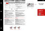
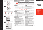
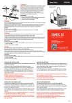
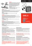
DESCRIPTION FACE AVANT RD1B2 2 1 3 ∂ Réglage du seuil d’intervention IΔ n À Sélection du calibre x1 / x10 / x100 9 ∂ Setting intervention threshold IΔ n À Range selector x1 / x10 / x100 0,03 30mA 300mA 3A x1 x10 x100 IΔ n 0,05 50mA 500mA 5A 0,075 75mA 750mA 7,5A 0,1 100mA 1A 10A Vérifier que la valeur d’intervention sélectionnée est compatible avec le seuil de sensibilité mini. du tore associé. 4 10781285 FRONT DESCRIPTION 0,15 150mA 1,5A 15A 0,2 200mA 2A 20A 0,3 300mA 3A 30A Check that selected intervention value matches the lowest sensibility detectable by the connected ring current transformer. 8 7 0n 11 0ff h.f.filter à ~ 6 10 à • Õ LED segnalazione On à • Õ Signaling LED Õ Trip / Fail • • Manque de tension alimentation auxiliaire ou appareil défectueux Lack of auxiliary voltage supply or out of order meter Z • Supervision • Supervision Z Z Alarme • Alarm Z •Z•Z Interruption du raccordement tore - relais Connection breakdown between relay and ring current transformer LED éteint LED allumé LED clignotant 5 • Z •Z•Z Œ Touche de test (t = 0 ) 0,03...0,3A 0,3...3A 3...30A RD1G2 RD1E2 2 4 6 5 Permet de vérifier le fonctionnement tore-relais, commutation LED Trip allumée et commutation relais. œ Touche de reset l’état du relais est actif jusqu’à ce que l’opérateur agisse sur la touche RESET. Le réarmement ne pourra s’effectuer lorsque le courant de défaut mesuré : > 50% IΔ n sélectionné – Sélection Al.2 / AL.50% Al.2 = relais alarme avec double contacts SPDT. Al.50% = relais alarme + relais préalarme. Le relais marqué 60 - 61 - 62 est un préalarme avec un seuil d’intervention fixe égal à 50% de la valeur IΔ n sélectionnée. — Sélection de l’état du relais de sortie: Nd (norm. désexcité) sécurité négative Ne (norm. excité) sécurité positive. Le relais de préalarme et normallement toujours désexcité. “ Réglage de la temporisation En réglant le seuil d’intervention sur la position 0,03 le délai d’intervention est automatiquement exclu, indépendemment de la position du sélecteur de calibre À Pour sélectionner le seuil d’intervention ∂ IΔ n = 30mA avec une intervention instantannée, sélectionnez 0,03 et assurez vous que le sélecteur À est en position x1. ” Indication instantanée du courant différentiel (en % de la valeur IΔ n sélectionnée.) Insertion (on) - exclusion (off) filtre pour les harmoniques. ATTENTION En raccordant le filtre pour les harmoniques, le différentiel ne doit pas être utilisé pour la protection des personnes. INSTRUCTIONS DE RACCORDEMENT • La position de montage n’affecte en rien le bon fonctionnement de l’appareil. • Les opérations de réglage (seuil d’intervention, temporisation, etc.) doivent être effectués avec l’appareil hors tension. • Suivre méthodiquement le schéma de raccordement : une erreur peut altérer le fonctionnement ou causer des dommages à l’appareil. • Pour le fonctionnement optimum du système de protection différentielle, les recommandations suivantes doivent être respectées: + Réduire autant que possible la distance entre le tore et le relais + Utiliser des câbles de raccordement tore-relais blindés ou torsadés + Eviter de placer les câbles de raccordement tore-relais parallèlement à des raccordements de puissance. + Eviter d’installer le tore et le relais près d’une source de champ électromagnétique (gros transformateurs). + Passer dans le tore uniquement un conduceur actif (des.D1) + Si vous utilisez du câble blindé, l’armature doit être raccordée à la terre (des.D2) + Assurez vous que le conducteur soit positionné au centre du tore (des.D3). n 10 1 9 (t = 0 ) 7 3 8 Guide d’utilisation User’s Guide Œ œ LED off LED on LED blinking Test key It allows to simulate alarm condition, LED Trip switching on and output relay switching. Reset key the alarm stays until the operator doesn’t act on RESET key. Reset is not possible with persistent residual current: > 50% IΔ n. I Cod. RD1B2 - RD1E2 - RD1G2 ISTRUMENTI MISURE ELETTRICHE SpA – Selector Al.2 / AL.50% Al.2 = alarm relay with double SPDT exchange. Al.50% = alarm relay + pre-alarm relay. Relay marked 60 - 61 - 62 is a prealarm state with fixed intervention threshold, equal to 50% of selected IΔ n value. — Switch for state of output relay: Nd (normally de-energised) negative security Ne (normally energised) positive security. Pre-alarm relay is always normally de-energized. “ Setting intervention delay Selecting the intervenction threshold on position 0,03 the intervention delay is automaticall excluded, independently of position of range selector, À. To set intervention threshold ∂ IΔ n = 30mA with instantaneous intervention, select 0,03 and make sure that selector À is on position x1. ” Instantaneous display of earth leakage current (in % of selected IΔ n value) On-off harmonic filter ATTENTION By connecting the harmonic component filter, the differential must not be used to protect people. WIRING INSTRUCTIONS • Mounting position do not affect in any way the proper working. • Setting operations (intervention threshold, delay time, etc.) must be carried out with non-fed meter. • Please carefully follow the wiring diagram; an error in connecting the relay may give rise to irregular working or damages. • Four full functional of the earth relay the following installation recommendation should be adopted. + To reduce as much as possible the distance between ring current transformer and relay. + To use only shielded or twisted cables for their connection + To avoid in placing ring current transformer-relay connection cables parallelly to power wires + To avoid in mounting ring current transformer and relay near sources of intense electromagnetic fields (big transformers). + Pass active conductor only through toroid (draw D1) + When using blind cable, ensure ground connection of armature (draw D2) + Ensure the central positioning of conductor through toroid (draw D3). n Via Travaglia 7 20094 CORSICO (MI) ITALY Tel.+ 39 02 4 878.1 www.imeitaly.com [email protected] 03/10 DIMENSIONS • OVERALL DIMENSIONS D1 D2 D3 X=Y=Z 65,6 X L1 89,5 L3 L2 Y N L3 L1 45 N L2 Z PE 44 70 TORE FERME / CLOSED CORE 72 96 96 72 92 68 (1) TORE OUVRANT / OPEN CORE CODE CODE PASSAGE DE CÂBLE PASSING CABLE IΔn min A In A Imax A TDGA2 Ø 28 0,03 65 TDGB2 Ø 35 0,03 TDGH2 Ø 60 TDGC2 (2) CODE CODE PASSAGE DE CÂBLE PASSING CABLE IΔn min(1) A In A Imax(2) A 390 TDAA2 Ø 110 0,5 250 1500 70 420 TDAB2 Ø 150 0,5 250 1500 0,03 90 540 TDAC2 Ø 300 1 630 3780 Ø 80 0,05 170 1020 TDGD2 Ø 110 0,1 250 1500 TDGE2 Ø 140 0,3 250 1500 TDGF2 Ø 210 0,3 400 2400 (1) 68 RD1E2 92 RD1G2 75 72 RD1E2 96 RD1G2 SECURITE NEGATIVE • NEGATIVE SECURITY S 291/104 S 291/103 AUX.SUPPLY (+) (-) 20 21 AL.2 RESET TEST TRIP 19 18 17 60 61 62 4 6 TRANSFORMER 3 2 1 TRIP RESET TEST 19 18 17 60 61 62 4 6 TRANSFORMER Ba 19 18 17 60 61 62 RESET TEST 4 6 TRANSFORMER 3 2 1 6 TRIP 50% RESET TEST 19 18 17 60 61 62 4 6 TRANSFORMER 3 2 1 TRANSFORMER RESET TEST 19 18 17 60 61 62 4 6 3 2 1 B A Bm TD TD L1 L2 L3 N SECURITE POSITIVE • POSITIVE SECURITY AUX.SUPPLY (+) (-) 20 21 B A S 291/99 TRIP 50% 19 18 17 60 61 62 TRANSFORMER RESET TEST 4 6 3 2 1 50% 19 18 17 60 61 62 TRANSFORMER RESET TEST 4 6 3 2 1 Ba TD L1 L2 L3 N TRIP AUX.SUPPLY (+) (-) 20 21 B A Bm TD L1 L2 L3 N 3 2 1 TRIP AUX.SUPPLY (+) (-) 20 21 B A Al.50% Ba TD L1 L2 L3 N 4 S 291/102 AUX.SUPPLY (+) (-) 20 21 B A Bm 19 18 17 60 61 62 L1 L2 L3 N S 291/101 S 291/100 TRANSFORMER RESET TEST TD SECURITE NEGATIVE • NEGATIVE SECURITY 50% TRIP Ba B A L1 L2 L3 N TRIP S 291/106 AUX.SUPPLY (+) (-) 20 21 3 2 1 TD L1 L2 L3 N AUX.SUPPLY (+) (-) 20 21 SECURITE POSITIVE • POSITIVE SECURITY S 291/105 AUX.SUPPLY (+) (-) 20 21 B A Bm Courant min. IΔn valeur min. de IΔn sélectionnable sur le relais de protection raccordé à la terre. IΔn lowest current IΔn lowest value that can be set on earth leakage relay connected with toroid (2) Courant de test correspondant à 6In: Imax (EN 60947-2 annexe M) Test current corresponding to 6In: Imax (EN 60947-2 annex M) B A TD L1 L2 L3 N