1
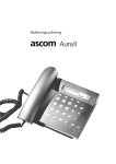
INDUSTRONIC Industrie-Electronic GmbH & Co.KG Carl-Jacob-Kolb-Weg 1 97877 Wertheim / Germany Tel.: +49(0)9342-871-0 Fax.: +49(0)9342-871-565 email: [email protected] Maßzeichnung Dimensional drawing Anschlussplatine 1 DAA 01 Connection board 1 DAA 01 Maßeinheit: mm unit of measurement: mm Bohrschema mounting template Bedienungsanleitung Sprechstelle DAX 004/DAX 014 für Ex-Zone 2 / Zone 22 Instructions for Intercom Station DAX 004/ DAX 014 for Ex Zone 2 / Zone 22 Lautsprecher loudspeaker X3 Mikrofon microphone Beschriftungsstreifen inscription plate Wahltastatur dial keypad Direktwahltaste push-to-talk switch Beispiel für 4 DAX 014 example of 4 DAX 014 Seite / page 1/6 028-007-161 Rev. 01 COM NC N0 La(+) / Lb(-) Relaiskontakt Mitte Relaiskontakt Öffner Relaiskontakt Schließer Datenleitung und Stromversorgung, Anschluss an INDUSTRONIC-Zentrale IN+ / INpotentialfreier Eingang +/ GND nicht benutzt RS485+ / RS485- nicht benutzt NFa / NFb nicht benutzt L100 / L0 100V NF-Ausgang Zusatzlautsprecher +V / -V Versorgung Zusatzverstärker + und COM NC N0 La(+) / Lb(-) common relay normally closed relay normally open relay data line and power supply, connection to INDUSTRONIC exchange IN+ / INpotential free input + / GND not used RS485+ / RS485- not used NFa / NFb not used L100 / L0 100V AF-output for the additional loudspeaker +V / -V power supply for the booster amplifier + and - Es leuchtet keine LED bei einer Tastenbetätigung: Die Sprechstelle ist nicht angeschlossen oder die Taste ist nicht im Verbindungsplan enthalten. Wandmontage und Sprechabstand Wall mounting and speaking distance Standardsignalisierungen und Tastenfunktionen Standard indications and key functions Die Außensprechstellen sollten in einer Höhe von ≈ 1180 - 1280 mm (Abstand Boden <-> Unterboden Sprechstelle) montiert werden. Die Gebrauchslage ist aufrecht (Lautsprecher oben, min. 75°). Der Abstand während des Sprechens beträgt ≈ 50 mm zum Mikrofon. Alle LEDs sind aus, es ist keine Taste gedrückt: Sprechstelle ist im Ruhezustand. The station should be mounted at a height of ≈ 1180 - 1280 mm (distance floor bottom of the station). The mounting position has to be upright (loudspeaker at top, min. 75°). The distance to the microphone while speaking should be ≈ 50 mm. Eine LED zeigt rotes Dauerlicht, die zugehörige Taste ist nicht gedrückt: Die auf der Taste programmierte Sprechstelle ist besetzt. Elektrische Daten Electrical data One LED shows permanent red light, the corresponding key is not pressed: The station which is programmed at the key is busy. Betriebsspannungsbereich La, Lb, +V , -V: operating voltage range La, Lb, +V, -V: 42 V - 68 V DC Ruhe-, max. Stromaufnahme: quiescent, max. current consumption: 20 mA, 100 mA Ruhe-, max. Stromaufnahme Zusatzverstärker: quiescent, max. current consumption booster amplifier: 60 mA, 850 mA Bedienung der Wahltastatur (nur Typ DAX 014) Operation of the dial keypad (type DAX 014 only) Auswahl der Zielstation durch Eingabe der Nummer der Zielstation. Signalton als Bestätigung bei jeder gedrückten Zifferntaste. Verbindungsaufbau mit der *-Taste. Akustisches Besetzt-Signal, falls Zielstation besetzt oder nicht erreichbar. Löschen der Nummerneingabe mit #-Taste. 25 Sekunden Dauerbetätigung der *-Taste beendet das aktuelle Gespräch automatisch. Funktion ist abhängig von der Systemparametrierung. Selection of the desired station by dialling the number of the destination. Signal tone as confirmation that a numerical key has been pressed. Start communication with the key *. Acoustic busy signal if target station is busy or cannot be addressed. Cancelling the dialled number by pressing key #. 25 seconds continuously pressing the * key automatically ends the current conversation. Function is depending on the system parametrization. All LEDs are off, no key is pressed: station is in idle position. Eine LED blinkt in schneller Folge: Eingehender Ruf von der Sprechstelle, welche auf dieser Taste programmiert ist. One LED flashes rapidly: Incoming call from the station which is programmed at the key. Eine LED blinkt langsam (Rufspeicherung optional): Nicht beantworteter Ruf von der Sprechstelle, welche auf dieser Taste programmiert ist. One LED flashes slowly (call storage only optionally available): Unanswered call of the station, which is programmed at the key. Eine LED zeigt rotes Dauerlicht, die zugehörige Taste ist gedrückt: Abgehender Ruf von der eigenen Sprechstelle an die Station, welche auf dieser Taste programmiert ist. Taste dabei gedrückt halten. All LED’s are off although the switch is being pressed: The station is not correctly installed or the button is not indicated in the connection program. Lautsprecherleistung/Schalldruck: 1W, 115dB loudspeaker output power/sound pressure level: Frequenzbereich/frequency range: 300 - 3400 Hz Spannungsbereich IN+ / IN voltage range IN+ / IN-: 12 V - 68 V DC : Relais / relay: 60VDC/30VAC; 0,5A; 20W Mechanische Daten Mechanical data Kabelverschraubungen/ cable glands: One LED shows permanent red light, the corresponding key is pressed: Outgoing call to the station which is programmed at the key, keep the switch pressed. 2 x M 20 1 x M 25 Gewicht / weight: ca. 4,4 kg Farbe / colour: RAL 3000 Fehlersuche Troubleshooting Umweltbedingungen und Normen Environmental requirements and standards Alle LEDs blinken: Die Sprechstelle ist in ihrer Initialisierungsphase und noch nicht betriebsbereit. Umgebungstemperatur / ambient temperature: -40°C - +55°C Lagertemperatur / storage temperature: -40°C - +70°C All LEDs are flashing: The station is initializing and is not yet ready. Luftfeuchtigkeit nicht kondensierend / humidity non-condensing: max. 90% LED 1 und LED 2 leuchten abwechselnd im Sekundentakt: Die Sprechstelle ist nicht im Verbindungsplan enthalten. Luftdruck / atmospheric pressure: 750 ... 1100 hPa Schutzart / ingress protection: IP 65 The LEDs 1 and 2 alternately flash every second: the station is not programmed in the connection program. EMV-Test (CE-Zeichen) / EMC test (CE sign): EN 55022 EN 61000-6-2 max. Umgebungsgeräuschpegel: max. ambient noise level: 110 dB LED 1 und LED 2 leuchten gleichzeitig im Sekundentakt kurz auf: Der Vermittlungsrechner ist außer Betrieb. The LEDs 1 and 2 simultaneously flash every second: The exchange controller is not working. Seite / page 2/6 028-007-161 Rev. 01 copyright by INDUSTRONIC 01/2007 Anschlusshinweise / Connection instructions Die Anschlüsse La, Lb, +V, -V dürfen ausschließlich mit den Ausgängen der zentralen Vermittlungseinrichtungen von INDUSTRONIC verbunden werden. Zum Anschluss sind nur Kabel mit verdrillten Doppeladern oder Sternviererverseilung zu verwenden. Die Polarität ist unbedingt zu beachten. Die Verkabelung und der Anschluß sind unter Beachtung von EN 60079-14 durchzuführen. Es muß überprüft werden, daß sämtliche angeschlossenen Leitungen korrekt befestigt sind (Zugprüfung). Nicht benutzte Leitungen sind zu isolieren. The terminals La, Lb,+V, -V may be connected only to the INDUSTRONIC central exchange outputs. Only twisted pair cables or star quad cables may be used. Please ensure correct polarisation of the cabling. The connections and the cabling must be performed in accordance to EN 60079-14. Please, check that all connected lines are correctly fixed (tension test). Unused lines must be insulated. Sprechstellentypen Types of intercom stations 2 DAX 004 2 DAX 004/25 4 DAX 004 4 DAX 004/25 Einsatzbereich / Application range II 3GD Zündschutzart/ Ex nAC IIC T4 Explosion protection: Ex tD A22 IP65 T100°C Zulassung / Approval: IBExU 06ATEXB014X Sicherheitshinweise Aufgrund des hohen Oberflächenwiderstandes besteht die Gefahr von elektrostatischen Entladungen. Das Gerät darf daher nur feucht gereinigt werden und nicht im Bereich geladener Staubpartikel installiert werden. Sie muß so angebracht werden, daß sie bei einem Fehler in der Anlage nicht dem mit hoher Geschwindigkeit austretenden Staub ausgesetzt ist. Nach der Inbetriebnahme muss die Bedienungsanleitung aus der Sprechstelle entfernt werden. Es darf kein Papier in der Sprechstelle bleiben. Die Sprechstelle darf nur geöffnet und angeschlossen werden, wenn die Versorgungsleitungen spannungslos sind oder sichergestellt ist, daß keine explosionsfähige Atmosphäre auftreten kann. Gleiches gilt für das Lösen und Stecken von Steckverbindern innerhalb des Geräts Falls das Gehäuse beschädigt ist, muß die Sprechstelle sofort außer Betrieb gesetzt werden. 6 DAX 004 6 DAX 004/25 Besondere Bedingungen für den sicheren Betrieb Die Sprechstelle darf nur in Bereichen mit einer niedrigen Gefahr der mechanischen Beschädigung installiert werden. Die Stromversorgung darf nur von einem Netzgerät mit Sicherheitstransformator nach EN 60742 geliefert werden. Es ist sicherzustellen, daß die Anschlussleitungen nicht mit Fremdspannung in Berührung kommen. Safety instructions 0 DAX 014 0 DAX 014/25 2 DAX 014 2 DAX 014/25 4 DAX 014 4 DAX 014/25 Due to the high surface resistance there is the danger of electrostatic discharges. Therefore, the station may only be cleaned wet and must not be installed in areas of charged dust particels. Select a position which guarantees that the station is not exposed to highly accelerated dust in the event of an accident. After installing the intercom station the instruction manual must be removed. No paper may be left inside the station housing. The station may only be opened and connected if the supply lines are voltagefree or if it is guaranteed that no potentially explosive atmosphere can arise. The same is valid for the connection and disconnection of internal plugs. If damages of the housing are noted, the station must be immediately put out of operation. Special conditions for safe operation The intercom station may only be installed in areas with a low risk of mechanical injury. The power must be supplied from an AC/DC converter with isolating transformer according to EN 60742. Make sure that the connection lines do not get into contact with external voltages. Seite / page 3/6 028-007-161 Rev. 01 INDUSTRONIC Industrie-Electronic GmbH & Co.KG Carl-Jacob-Kolb-Weg 1 97877 Wertheim / Germany Tel.: +49(0)9342-871-0 Fax.: +49(0)9342-871-565 email: [email protected] Schéma coté Carte de connexion 1 DAA 01 Unité : mm Schéma de perçage Manuel d’utilisation du poste interphone DAX 004 / DAX 014 pour zone explosive 2 / 22 haut-parleur X3 microphone bandes d’inscription clavier de numérotage Touche d’appel directe Exemple pour 4 DAX 014 page 4/6 028-007-161 Rev. 01 COM NC N0 La(+) / Lb(-) Contact de relais centre Contact de relais repos Contact de relais travail Ligne de données et alimentation électrique, Raccordement à la centrale INDUSTRONIC IN+ / INEntrée isolée galvaniquement +/GND non utilisé RS485+ / RS485- non utilisé NFa / NFb non utilisé L100 / L0 Sortie NF 100 V pour haut-parleur auxiliaire +V / -V Alimentation de l’amplificateur auxiliaire + et - Montage mural et distance entre interlocuteur et poste interphone Les postes interphones doivent être montés à une hauteur de ≈ 1180 – 1280 mm (distance sol <-> bas poste). Le poste interphone doit être posé bien droit (haut-parleur supérieur, min. 75°). L’écart à respecter entre l’interlocuteur et le microphone est de ≈ 50 mm. Utilisation du clavier de numérotage (seulement type . DAX 014) Sélection de la station de destination par saisie de son numéro. Signal sonore servant de confirmation à chaque pression d’une touche numérique. Etablissement de la liaison avec la touche *. Signal sonore occupé si la station de destination est occupée ou non joignable. Effacement de la saisie des numéros avec la touche #. Une pression de 25 secondes sur la touche * met fin automatiquement à la communication en cours. Cette fonction dépend de la configuration du système. Signalisations standard et fonctions des touches Données électriques Tous les DEL sont éteintes, aucune touche n’est enfoncée. L’interphone est en veille. Plage de tension de service La, Lb, +V, -V : 42 V - 68 V DC Courant de repos, courant max. consommé : 20 mA, 100 mA Une DEL brille d’une lumière rouge continue, la touche correspondante n’est pas enfoncée. Le poste interphone programmé sur cette touche est occupé. Courant de repos, courant max. pour 60 mA, 850 mA amplificateur supplémentaire : Puissance du haut-parleur/pression acoustique: 1 W, 115 dB Une DEL clignote rapidement : appel entrant provenant du poste interphone qui est programmé sur cette touche. Plage de fréquence : 300 - 3400 Hz Plage de tension IN+/IN- : 12 V - 68 V DC Une DEL clignote lentement (sauvegarde optionnelle de l’appel) : appel non répondu provenant du poste interphone qui est programmé sur cette touche. Une DEL brille d’une lumière rouge continue, la touche correspondante est enfoncée : appel sortant au poste interphone qui est programmé sur cette touche. Maintenir la touche enfoncée. Toutes les DEL clignotent : l’interphone se trouve en phase d’initialisation ou n’est pas encore opérationnel. Les DEL 1 et DEL2 clignotent en même temps toutes les secondes : L’ordinateur d’échange est hors service. Aucune DEL ne clignote lorsqu’une touche est enfoncée : l’interphone n’est pas raccordé ou la touche ne fait pas partie du plan de liaison. 028-007-161 Rev. 01 60 VDC/30 VAC; 0,5 A; 20 W Données mécaniques Vissages des câbles : 2 x M 20 1 x M 25 Poids : ca. 4,4 kg Coloris : RAL 3000 Recherche d’erreur Les DEL 1 et DEL2 clignotent à tour de rôle toutes les secondes : l’interphone ne fait pas partie du plan de liaison. page 5/6 Relais : Conditions climatiques et normes Température ambiante : -40°C - +55°C Température de stockage : -40°C - +70°C Humidité non condensée de l’air : max. 90% Pression atmosphérique : 750 ... 1100 hPa Type de protection : IP 65 Test CEM (sigle CE) : EN 55022 EN 61000-6-2 niveau maximal de bruit ambiant : 110 dB Consignes pour le raccordement Les raccords La, Lb, +V, -V doivent être connectés exclusivement aux sorties des commutateurs centraux d’INDUSTRONIC. N’utilisez que des câbles à double brin torsadé ou des câbles à quartes en étoile.Respectez impérativement la polarité. Le câblage et le raccordement doivent être réalisés conformément à la norme EN 60079-14.Il faut vérifier que toutes les lignes raccordées sont correctement fixées (test de résistance à la traction).Isolez les lignes non utilisées. Types de postes interphones 2 DAX 004 2 DAX 004/25 0 DAX 014 0 DAX 014/25 4 DAX 004 4 DAX 004/25 2 DAX 014 2 DAX 014/25 6 DAX 004 6 DAX 004/25 4 DAX 014 4 DAX 014/25 Zone d'utilisation Protection antidéflagrante: Certificat II 3GD Ex nAC IIC T4 Ex tD A22 IP65 T100°C IBExU 06ATEXB014X Consignes de sécurité Il existe un risque de décharges électrostatiques en raison de la grande résistance de surface. L’appareil doit, par conséquent, n’être nettoyé qu’avec un tissu humide et ne doit pas être installé dans une zone de particules de poussière chargées. Veuillez sélectionner un lieu adéquat pour le montage de poste, pour qu'il ne soit pas exposé à la poussière qui sort en grande vitesse en cas d'accident. Cette indication figure également en allemand et en anglais sur la plaque d'identité. Si l'appareil est installé dans un autre pays européen, veuillez utiliser l'autocollant correspondant à votre langue d'origine et qui est joint à ce poste d’intercommunication et collez-le en dessous de la plaque d'identité. L'autocollant doit être apposé lors du montage du poste de l’interphone. Une fois la mise en service effectuée, le manuel d’utilisation doit être retiré de l’interphone. Aucun papier ne doit resté dans l’interphone. L’interphone ne doit être ouvert et raccordé que si les lignes d’alimentation sont hors tension ou sécurisées de façon à ce qu’aucune atmosphère explosive ne puisse se former. Il en va de même pour la déconnexion et la connexion de connecteurs enfichables dans l’appareil. Si le boîtier est endommagé, l’interphone doit être aussitôt mis hors service. Conditions spéciales pour une utilisation sûre L’interphone ne doit être installé que dans des zones présentant un faible risque d’endommagement mécanique. L’alimentation électrique ne doit être fournie que par un bloc d’alimentation avec transformateur de sécurité répondant à la norme EN 60742. Il faut s’assurer que les lignes de raccordement ne risquent pas d’être en contact avec une tension externe. page 6/6 028-007-161 Rev. 01