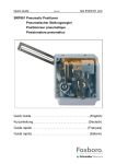
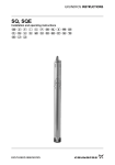
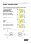
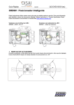
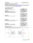
1
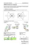
Quick Guide
10.2008
QG EVE0102(int)
SRI986 Electro-Pneumatic Positioner
Elektro-pneumatischer Stellungsregler
Positionneur électro-pneumatique
Posizionatore elettro-pneumatico
Electro-pneumatski positioner
Quick Guide . . . . . . . . . . . . . . . . . . . . . . . . . . . . . . . . . (English)
Kurzanleitung . . . . . . . . . . . . . . . . . . . . . . . . . . . . . . . (Deutsch)
Guide rapide . . . . . . . . . . . . . . . . . . . . . . . . . . . . . . . . (Français)
Guida rapida . . . . . . . . . . . . . . . . . . . . . . . . . . . . . . . . . (Italiano)
Kratko uputstvo. . . . . . . . . . . . . . . . . . . . . . . . . . . . . . . . (Srpski)
SRI986
QG EVE0102 (int)
Quick Guide
QG EVE0102 (en)
10.2008
SRI986 ELECTRO-PNEUMATIC POSITIONER
These instructions are to be used as a guide for quick start-up. For more detailed information please
refer to the standard documents “Master Instructions” and “Product Specification Sheet”. These can
be found on our Website www.foxboro-eckardt.com .
1 MOUNTING TO LINEAR ACTUATORS
Single-acting diaphragm actuators
Check whether the actuator is in the safety position required by the process. (Does the actuator open
or close with spring force?) The mounting side is selected from the table below in accordance with the
direction of action and the required direction of movement of the spindle for an increasing input signal.
The arrow indicates the
direction of movement of the
spindle at increasing input
signal.
The direction of action of the
input signal can be set on
the changeover plate 13 :
N = Normal direction of
action
(increasing
input
signal produces increasing
control pressure to the
actuator)
U = Reverse direction of
action
(increasing
input
signal produces decreasing
control pressure to the
actuator)
Double-acting diaphragm actuators
For double-acting positioners the changeover plate 13 always stays in the “N” setting. The assignment
of the input signal to the direction of movement of the actuator spindle is determined by the selection
of the mounting side of the positioner and the piping of the positioner outputs to the actuator:
M
12
ensure that the feedback lever 11 is horizontal at 50 % stroke.
Fasten housing cover in such a way that air vent of attached device faces downwards (see
Mark ‘M‘).
11
2
SRI986
QG EVE0102 (en)
2 MOUNTING TO ROTARY ACTUATORS
a) Remove the transparent cover plate from the
housing of the attachment kit.
b) Mount the housing of the attachment kit on
rotary actuator or armature; use mounting
hardware
supplied
by
the
actuator
manufacturer if necessary.
c) Move actuator into the desired starting
position (rotation angle = 0°).
d) Mount cam 24 in accordance with the
direction of rotation of the actuator.
The linear cam is fastened to the actuator
drive shaft in such a manner that the distance
x between the inside of the housing and the
came amounts 2 mm, whereas in case of
equal percentage cam the dimension x is
approx. 17.5 mm.
In case of inverse equal percentage cam the
dimension x is approx. 18 mm.
When employing equal percentage and the
inverse equal percentage cams, the range
spring (yellow) EW420493013 must be
installed in the positioner.
e) Fasten feedback lever 30 for the rotary
actuator onto shaft 15 of positioner.
x
f) Mount positioner on housing of attachment kit.
Attach spring 31 to feedback lever 30 and
cam follower 32 against cam.
Screw positioner to housing of attachment kit.
With the linear cam and the inverse equal
percentage cam check whether mark 33points
to the center of the cam follower 32; adjust if
necessary.
With the equal percentage cam check
whether the cam follower lies directly ahead of
the start of the cam lobe; adjust if necessary.
g) Final mounting of feedback lever on shaft of
positioner is performed at a stroke of 0 %, i.e.
a rotation angle of 0°. First loosen 5 mm A/F
Allen screw of feedback lever 30 through hole
34, then press stroke factor lever 17 against
stop screw 18 (see page 5) and tighten Allen
screw firmly.
34
Note !
If actuator moves to an end position, the mounting position of cam
does not coincide with the direction of rotation of the actuator. In this
case install the cam 24 in the reverse position.
QG EVE0102 (en)
SRI986
3
3 PNEUMATIC CONNECTIONS
Air supply (s): 1,4 to 6 bar (but not more than the
max. pressure of actuator), free of oil, dust and water !
6 Internal thread G 1 /8 for output II (y2)
(only on double-acting positioners)
7 Internal thread G 1 /8 for supply air
8 Internal thread G 1 /8 for output I (y1)
8
7
6
4 ELECTRICAL CONNECTIONS
The safety requirements of the document EX EVE0001 as well as the requirements of the PSS
EVE0102 and MI EVE0102 for the SRI986 must be observed
4.1 Input signal
Input 4 to 20 mA
4.2 Option “Limit switch”
The limit switches is an accessory either installed in the factory or retrofit.
This unit can consist of either inductive slot type sensors or micro-switches.
Warning : For the connection of microswitches please refer you to the MI (Master
Instruction)
and
respect
the
safety
requirements of the document EX EVE0001.
4
SRI986
QG EVE0102 (en)
4.3 Option “Position Transmitter 4-20mA”
The electrical position transmitter is an accessory either installed in the factory or retrofit. It converts
the stroke or rotary movement of an actuator into an electrical standard signal 4-20 mA.
Analog output 4 to 20mA
2 wire system
Supply voltage DC 11 to 48 V
S1
S2
5 SETTINGS AND START UP
5.1 Setting of zero point and stroke on the positioner
(see page 6 for the reference of the number)
Before starting with the set-up push the flapper lever 40 several times
alternately to the left and right in order to align the flappers correctly.
a) Set the minimum value of the input signal w (start of stroke).
b) Turn zero screw 41 until actuator just begins to move from its end
position.
c) Set maximum value of the input signal w (end of stroke).
d) Turn the stroke factor screw 42 until actuator precisely reaches its
end position:
Right turn: decrease of travel
Left turn: increase of travel
Repeat the operations (a to d) 2 or 3 times in order to insure an accurate positioning.
41
42
Note:
Changes of the gain will influence the settings of zero and span.
If the stroke cannot be adjusted with the installed spring, a suitable spring can be determined with the
table on page 5.
5.2 Adapting to air supply
The positioner is adjusted in the factory for an air supply pressure of 3 bar. If the device will be used
with a different air supply pressure, the gain has to be adjusted with screw 44. For a higher air supply
pressure the screw should be moved clockwise (for 6 bar to the end).
QG EVE0102 (en)
SRI986
5
5.3 Setting the damping
The air output capacity of the positioner can be reduced by means of the damping throttle 46. Doubleacting positioners are equipped with a damping throttle 47 for correcting the variable y1 and a
damping throttle 48 for correcting the variable y2 . In its normal setting the damping throttle is
approximately flush with the amplifier housing.
The air output capacity is reduced by a factor of approximately 2.5 when the damping throttle is turned
completely.
5.4 Setting and Start Up of position transmitter 4-20mA
Attachment and start-up of the unit to the actuator must be performed according MI EVE0102 A or MI
EVE0101 A. At 50% stroke, the control lever must be horizontal.
The electronic connection of the position transmitter must be assured. Both LED’s are then light up.
Adjusting the start of the measuring range (4mA)
a) Move the actuator to the starting position.
b) Press push button S1 „Config Output 4mA“ longer than 2 seconds. During this time LED 1 lights
up. After 2 seconds both LED’s are light up again, the value for 4mA is stored.
Adjusting the end of the measuring range (20mA)
a) Move the actuator to the end position.
b) Press push button S2 „Config Output 20mA“ longer than 2 seconds. During this time LED 2 lights
up. After 2 seconds both LED’s are light up again, the value for 20mA is stored.
Random adjustment of the current values at the end points
a) Move the actuator to the end position, where you want to adjust the current.
b) Press both buttons simultaneously for about 2 seconds. Then both LED’s are alternating flashing in
a slow frequency.
c) With push button S1 „Config Output 4mA“ the output current value can be decreased and with
push button S2 „Config Output 20mA“ the output current value can be increased. Pressing the
buttons for a short moment results in a small change and pressing the button for a longer time
results in a fast mode for a bigger change. The value of the current can be freely decreased
approximately between 3,3 and increased up to 22,5 mA.
d) Without any additional manipulations of the push buttons the new value is automatically saved.
After a few seconds, the device returns into the normal operating mode, indicated by both LED’s
that are then light up again.
Trouble shooting of the position transmitter
The components of the position transmitter are under constant surveillance by the installed micro
controller. Errors are detected and indicated when both LED’s are off or both LED’s are parallel
flashing at a fast frequency.
In the event of a fatal error, e.g. potentiometer not connected, an output current of 24mA will be shown
in addition to the error indication given by the LED’s (fast flashing).
In this case check the following:
a) if the potentiometer is correctly connected to the electronic board.
b) if the potentiometer is within its working span.
When both LED’s are off, the supply voltage should be checked (minimum tension, polarity).
6
SRI986
QG EVE0102 (en)
5.5 Spring range
Five different springs for the travel-ranges are available for matching to the stroke and input signal
range.
In the following table the stroke range is given for a normal application (4-20mA and with our standard
feedback lever).
Spring range
Ident N°
Colour
EW420493013
Yellow
EW420494019
green
EW502558017
- without EW420496011
gray
EW420495014
blue
Stroke range
in mm
8 - 34
17 - 68
28 - 105
40 - 158
55 - 200
Remarks
Built-in
5.6 Functional designation
Subject to alterations – reprinting, copying and translation prohibited. Products and publications are normally
quoted here without reference to existing patent, registered utility models or trademarks. The lack of any such
reference does not justify the assumption that a product or symbol is free.
FOXBORO ECKARDT GmbH
Pragstrasse 82
D-70376 Stuttgart
Germany
Tel. + 49(0)711 502-0
Fax + 49(0)711 502-597
http://www.foxboro-eckardt.de
DOKT 534 043 102
ECKARDT S.A.S.
20 rue de la Marne
F-68360 Soultz
France
Tel. + 33 (0)3 89 62 15 30
Fax + 33 (0)3 89 62 14 85
http://www.foxboro-eckardt.com
Kurzanleitung
QG EVE0102 (de)
10.2008
SRI986 ELEKTRO-PNEUMATISCHER STELLUNGSREGLER
Diese Instruktionen dienen als Anleitung für eine schnelle Inbetriebnahme. Ausführlichere Informationen sind in den Dokumenten “Inbetriebnahme- und Wartungsanleitung” und “Typenblatt”, die Sie auch
auf unserer Webseite www.foxboro-eckardt.de finden.
1 MONTAGE AN LINEARANTRIEBE
Festlegen der Montageseite Einfachwirkende Membranantriebe
Überprüfen, ob die durch das Verfahren erforderliche Sicherheitsstellung des Antriebes gegeben ist.
(Öffnet oder schließt der Antrieb mit Federkraft?) Entsprechend dieser Wirkungsrichtung und der notwendigen Bewegungsrichtung der Spindel bei steigendem Eingangssignal wird laut nachstehender
Tabelle die Montageseite ausgewählt.
Der Pfeil gibt die Bewegungsrichtung der Spindel bei steigendem Eingangssignal an.
Die Wirkungsrichtung des Eingangssignals kann am Umschaltplättchen 13 (siehe S. 5)
eingestellt werden:
N = normale Wirkungsrichtung
(steigendes
Eingangssignal
bewirkt steigenden Stelldruck
zum Antrieb)
U = umgekehrte Wirkungsrichtung (steigendes Eingangssignal bewirkt fallenden Stelldruck zum Antrieb).
Doppeltwirkende Membranantriebe
Beim doppeltwirkenden Stellungsregler bleibt das Umschaltplättchen 13 immer in Stellung “N”. Die
Zuordnung des Eingangssignals zur Bewegungsrichtung der Antriebsspindel wird durch die Wahl der
Anbauseite des Stellungsreglers und die Verrohrung der Stellungsreglerausgänge zum Antrieb bestimmt:
M
12
Anlenkhebel 11 muss bei 50 % Hub waagerecht stehen.
Gehäusedeckel so anschrauben, daß sich die Kondenswassernase bei angebautem Gerät unten befindet (siehe Markierung ‘ M‘).
11
2
SRI986
QG EVE0102 (de)
2 ANBAU AN SCHWENKANTRIEBE
a) Sichtfenster vom Gehäuse des Anbausatzes
abschrauben.
b) Gehäuse des Anbausatzes auf den Schwenkantrieb bzw. die Armatur montieren, ggf. Montage-zubehör des Antriebsherstellers verwenden.
c) Schwenkantrieb in die gewünschte Ausgangsstellung bringen (Drehwinkel = 0°).
d) Kurvenscheibe 24 entsprechend der Drehrichtung des Antriebes montieren (siehe Abb.
14). Die lineare Kurvenscheibe wird dabei so
an die Anschlusswelle geschraubt, daß das
Maß x (Abstand zwischen GehäuseInnenwand und Kurvenscheibe) = 2 mm beträgt, wogegen bei der gleichprozentigen Kurvenscheibe das Maß x ≈ 17,5 mm betragen
muß. Bei der inversen, gleichprozentigen Kurvenscheibe sind die Maße x ≈ 18 mm. Bei
Verwendung der gleichprozentigen und der
inversengleich-prozentigen Kurvenscheibe ist
die Messfeder (gelb) EW420493013 in den
Stellungsregler einzubauen.
e) Anlenkhebel 30 für Schwenkantrieb zunächst
so auf der Durchführungswelle 15 befestigen,
f) Stellungsregler auf das Gehäuse des Anbausatzes aufsetzen. Dabei die Feder 31 in den
Anlenkhebel 30 einhängen und die Abtastrolle
32 an die Kurven Scheibe anlegen.
Bei gleichprozentiger Kurvenscheibe prüfen,
ob die Abtastrolle unmittelbar vor Beginn der
Kurvensteigung liegt, ggf. korrigieren.
g) Die endgültige Befestigung des Anlenkhebels
auf der Durchführungswelle erfolgt bei Hubstellung 0 %, d. h. Drehwinkel 0°. In dieser
Stellung die Innensechskantschrauben SW 5
des Anlenkhebels 30 durch die Bohrung 34
hindurch zunächst Ibsen, die Stell-vorrichtung
17 gegen die Anschlagschraube 18 drücken
(siehe S. 5) und dann die Innensechskantschraube fest anziehen.
Achtung !
Wenn der Antrieb in eine Endstellung Iäuft, dann
stimmt die Einbaulage der Kurvenscheibe nicht mit
der Drehrichtung des Antriebs überein. In diesem
Falle ist die Kurvenscheibe 24 in umgekehrter Lage
einzubauen.
x
34
QG EVE0102 (de)
SRI986
3
3 PNEUMATISCHE ANSCHLÜSSE
Zuluftversorgung (s): 1,4 bis 6 bar (aber nicht höher als der Maximaldruck des Antriebes), frei von
Öl, Staub und Wasser !
6 Einschraubloch G 1/8 für Ausgang II (y2)
(nur bei Doppeltwirkenden Stellungsreglern)
7 Einschraubloch G 1/8 für Zuluft
8 Einschraubloch G 1/8 für Ausgang II (y1)
8
7
6
4 ELEKTRISCHE ANSCHLÜSSE
Die Sicherheitsbestimmungen im Dokument EX EVE0001 sowie die Bestimmungen in PSS EVE0102
und MI EVE0102 müssen beachtet werden.
4.1 Sollwert
Eingang 4 bis 20 mA
4.2 Option „Induktiver Grenzwertgeber“
Die Grenzwertgeber sind eine ab Werk eingebaute oder auch nachrüstbare Zusatzausstattung. Sie
sind mit Induktivschaltern oder Mikroschaltern aufgebaut und signalisieren die Über- oder Unterschreitung einer Hub- oder Schwenkbewegung von Stellgeräten.
Achtung: Beim Anschluss der Mikroschalter sind die Hinweise in der MI
(Inbetriebnahme- und Wartungsanleitung) sowie die Sicherheitsbestimmungen im Dokument EX EVE0001 zu
beachten.
4
SRI986
QG EVE0102 (de)
4.3 Option „Stellungsrückmeldung 4-20mA”
Der elektrische Stellungsrückmeldung ist eine ab Werk eingebaute oder auch nachrüstbare Zusatzausstattung. Er formt die Hub- oder Schwenkbewegung eines Stellgerätes um in ein elektrisches Einheitssignal 4...20 mA.
Analog Ausgang 4 bis 20mA
Zweidraht System
zu versorgen mit DC 11 bis 48 V
S1
S2
5 INBETRIEBNAHME
5.1 Einstellen von Nullpunkt und Hub
(siehe Seite 6 für die Positionsnummern)
Vor Beginn der Einstellungen Prallplattenhebel 40 mehrmals wechselweise nach links und nach rechts
drücken, damit sich die Prallplatten korrekt ausrichten.
a) Anfangswert für Führungsgröße w vorgeben (Hubanfang).
b) Nullpunktschraube 41drehen, bis sich der Antrieb von seiner Endlage aus gerade zu bewegen beginnt.
c) Endwert für Führungsgröße w vorgeben (Hubende).
d) Hubfaktorschraube 42 drehen, bis der Antrieb genau seine Endstellung erreicht:
Rechtsdrehung: Hubverkleinerung
Linksdrehung: Hubvergrößerung
Punkte a) bis d) 2-3mal wiederholen, um hohe Positioniergenauigkeit zu erreichen.
Die Einstellungen beeinflussen sich gegenseitig.
41
42
Hinweis:
Nach jeder Änderung der Verstärkung ist der Nullpunkt neu einzustellen.
Kann der Hub mit der eingebauten Feder nicht eingestellt werden, so muss eine andere Feder verwendet werden. Siehe Tabelle Seite 5.
5.2 Anpassen an Zuluftdruck
Der Stellungsregler ist ab Werk für einen Zuluftdruck von 3 bar eingestellt. Wird das Gerät bei einem
abweichenden Zuluftdruck betrieben, muß die Verstärkung mit Hilfe der Schraube 44 angepasst werden. Dabei ist bei größerem Zuluftdruck die Schraube im Uhrzeigersinn zu drehen (bei 6 bar bis zum
Anschlag).
QG EVE0102 (de)
SRI986
5
5.3 Einstellen der Dämpfung
Mit der Dämpfungsdrossel 46 kann die Luftleistung des Stellungsreglers vermindert werden. Beim
Doppeltwirkenden Stellungsregler gibt es eine Dämpfungsdrossel 47 für die Stellgröße y1 und eine
Dämpfungsdrossel 48 für die Stellgröße y2 . In Normalstellung schließt die Dämpfungsdrossel etwa
mit dem Verstärkergehäuse ab. Durch vollständiges Hineindrehen der Dämpfungs-drossel wird die
Luftleistung etwa um den Faktor 2,5 reduziert.
5.4 Einstellung der Stellungsrückmeldung 4 bis20mA
Das Gerät muß an den Antrieb angebaut und in Betrieb genommen werden, wie in MI EVE0102 A
bzw. MI EVE0101 A, beschrieben. Bei 50% Hub muss der Anlenkhebel waagrecht stehen.
Der Stellungsumformer muss korrekt angeschlossen sein. Beide LED’s leuchten.
Einstellen von Messbereichsanfang (4mA)
a) Stellantrieb in Anfangsstellung fahren
b) Drücken der Taste S1 „Config Output 4mA“ länger als 2s. Während dieser Zeit leuchtet LED 1.
Nach 2s leuchten wieder beide LED’s, der 4mA-Wert ist damit gespeichert.
Einstellen von Messbereichsende (20mA)
a) Stellantrieb in Endstellung bringen
b) Drücken der Taste S2 „Config Output 20mA“ länger als 2s. Während dieser Zeit leuchtet LED 2.
Nach 2s leuchten wieder beide LED’s, der 20mA-Wert ist damit gespeichert.
Freies Einstellen der Stromwerte an den Endpunkten
a) Den Stellantrieb zu demjenigen Endpunkt bringen, an welchem der Stromwert eingestellt werden
soll.
b) Beide Tasten gleichzeitig für ca. 2s drücken. Danach leuchten beide LED’s abwechselnd im Sekundentakt (Einstellmodus).
c) Mit der Taste S1 „Config Output 4mA“ kann der Stromwert am Ausgang verringert und mit der Taste S2 „Config Output 20mA“ kann der Stromwert am Ausgang erhöht werden. Ein kurzes Drücken
bewirkt eine kleine Änderung, während ein langes Drücken eine große Änderung bewirkt. Der
Ausgangsstrom kann beliebig zwischen ca. 3,3 und 22,5 mA eingestellt werden.
d) Ohne eine Betätigung der Tasten wird der Wert gespeichert. Nach einigen Sekunden wird automatisch in den normalen Betreibsmodus zurückgeschaltet und beide LED’s leuchten wieder.
Fehlerbehebung beim Stellungsumformer
Die Komponenten des Stellungsumformers werden ständig durch den vorhandenen Mikrocontroller
überwacht. Fehlfunktionen sind daran zu erkennen, dass entweder beide LED’s aus sind oder beide
LED’s gleichzeitig in schneller Folge ein- und ausgeschaltet werden (Problemmeldung).
Bei gravierenden Fehlern, z.B. Potentiometer nicht vorhanden, wird zusätzlich zur Problemmeldung
ein Ausgangsstrom von größer 24mA ausgegeben.
In diesem Fall ist zu überprüfen:
a) Der korrekte Anschluß des Potentiometers an die Leiterplatte.
b) Der Betrieb des Potentiometers innerhalb seines Arbeitsbereiches.
Wenn beide LED’s aus sind, ist die Stromversorgung zu überprüfen (Mindestspannung, Polarität).
6
SRI986
QG EVE0102 (de)
5.5 Federbereiche
Zur Anpassung an Hub und Eingangssignalbereich stehen 5 verschiedene Meßfedern zur Verfügung.
In der folgenden Tabelle sind die Federn und ihre Hubbereiche aufgeführt für normale Anwendungen
mit 4-20 mA und Standard-Anlenkhebel.
Meßfeder
Ident Nr
Farbe
EW420493013
gelb
EW420494019
grün
EW502558017
- ohne EW420496011
grau
EW420495014
blau
Hubbereich in
Bemerkungen
mm
8 - 34
17 - 68
eingebaut
28 - 105
40 - 158
55 - 200
5.5 Funktionsbezeichnungen
Änderungen vorbehalten – Nachdruck, Vervielfältigung und Übersetzung nicht gestattet. Die Nennung von Waren
oder Schriften erfolgt in der Regel ohne Erwähnung bestehender Patente, Gebrauchsmuster oder Warenzeichen.
Das Fehlen eines solchen Hinweises begründet nicht die Annahme, eine Ware oder ein Zeichen seien frei.
FOXBORO ECKARDT GmbH
Pragstrasse 82
D-70376 Stuttgart
Germany
Tel. + 49(0)711 502-0
Fax + 49(0)711 502-597
http://www.foxboro-eckardt.de
DOKT 534 043 102
ECKARDT S.A.S.
20 rue de la Marne
F-68360 Soultz
France
Tel. + 33 (0)3 89 62 15 30
Fax + 33 (0)3 89 62 14 85
http://www.foxboro-eckardt.com
Quick Guide
QG EVE0102 (fr)
10.2008
SRI986 POSITIONNEUR ELECTRO-PNEUMATIQUE
Ces instructions sont une aide pour une mise en service rapide. Pour plus d’informations sur le produit
veuillez vous reporter aux documents standards « manuel d’utilisation » et « fiches techniques »
disponibles sur internet à l’adresse www.foxboro-eckardt.com
1 MONTAGE SUR SERVOMOTEURS LINEAIRES
Servomoteurs simple effet à membrane
S’assurer que le servomoteur se trouve dans la position de sécurité requise par les opérations.
(Est ce que le servomoteur est ouvert ou fermé par la force d’un ressort ?) Le côté du montage doit
être choisi en fonction du tableau ci-après conformément au sens d’action souhaité et également en
fonction du sens de déplacement de la tige lorsque le signal d’entrée augmente.
Le ressort ferme le
servomoteur
La flèche indique le sens de
déplacement de la tige lorsque le
signal d’entrée augmente.
Le sens d’action du signal d’entrée
peut être réglé au moyen de la
plaquette de commutation 13
(page 6):
N = sens d’action normal
(l’augmentation du signal d’entrée
engendre une augmentation de la
pression de positionnement en
direction du servomoteur)
U = sens d’action inversé (l’augmentation du signal d’entrée engendre une diminution de la pression
de positionnement en direction du servomoteur)
Servomoteurs double effet à membrane
Lorsqu’il s’agit d’un positionneur à double effet, la plaquette de commutation 13 demeure toujours en
position « N ». L’adaptation du signal d’entrée au sens de déplacement de la tige d’entraînement est
déterminée par le choix du côté du montage du positionneur et par la tuyauterie des sorties du
positionneur en direction du servomoteur :
M
12
S’assurer que le levier d’accouplement 11 est horizontal avec une course de 50 %.
Fixer le couvercle de boîtier de telle sorte que l’évent (échappement d’air) soit vers le dessous
(voir repère « M »).
11
2
SRI986
QG EVE0102 (fr)
2 MONTAGE SUR SERVOMOTEURS ROTATIFS
a) Dévisser la plaque de visualisation dans le
boîtier du kit de montage.
b) Monter le boîtier du kit de montage sur le
servomoteur rotatif ou sur la vanne. Se servir
éventuellement des accessoires de montage
fournis par le fabricant du servomoteur.
c) Amener le servomoteur rotatif dans la position de
départ requise (angle de rotation = 0°)
d) Monter la came 24 en fonction du sens de
rotation du servomoteur. A cet effet, visser la
came linéaire à l’axe de raccordement de telle
sorte que la distance x séparant l’intérieur du
boîtier et la came soit de 2 mm. La cote x doit
être de 17.5 mm environ pour la came à
pourcentage égal et 18 mm environ pour la came
à pourcentage égal inverse. En cas d’utilisation
de la came à pourcentage égal ou de celle à
pourcentage égal inverse, monter à l’intérieur du
positionneur le ressort de mesure (repère jaune,
voir tableau page 6) EW420493013.
e) Fixer le levier d’accouplement
30 du
servomoteur rotatif tout d’abord sur l’axe de
traversée 15.
f) Mettre le positionneur en place sur le boîtier du
kit de montage. A cet effet, accrocher le ressort
31 dans le levier d’accouplement 30 et appuyer
le galet-palpeur 32 contre la came.
Visser le positionneur sur le boîtier du kit de
montage. Avec une came linéaire ou à
pourcentage égal inverse, vérifier si le repère 33
est orienté vers le centre du galet-palpeur 32,
rectifier sa position si nécessaire. Avec une came
à pourcentage égal, vérifier que le galet-palpeur
se trouve juste devant le pas de la came, rectifier
si nécessaire.
Pourcentage égal inverse
Linéaire
A = Position de montage
si le sens de rotation du
servomoteur est
B = Position de montage
si le sens de rotation du
servomoteur est
x
g) La fixation définitive du levier d’accouplement sur
l’axe de traversée doit s’opérer pour une position
de course de 0%, c’est-à-dire lorsque l’angle de
rotation vaut 0°. Dans cette position, desserrer
tout d’abord la vis à six pans creux (surplat 5mm)
du levier d’accouplement 30 à travers l’orifice 34,
puis presser le dispositif de positionnement
contre la vis de butée 18 (voir page 6) et serrer à
fond la vis à six pans creux.
Attention !
Si le servomoteur atteint une pression extrême, la position de
montage de la came ne correspond pas au sens de rotation du
servomoteur. Dans ce cas, il faut monter la came dans le sens
contraire.
34
Pourcentage égal
QG EVE0102 (fr)
3
SRI986
3 RACCORDEMENTS PNEUMATIQUES
Air d’alimentation (s) : 1,4 à 6 bar (en respectant la
pression de travail maximum du servomoteur), air
propre, déshuilé, sans poussière ni eau (suivant CEI
648)!
6 Raccord pneumatique G 1 /8 pour sortie II (y2)
(sur positionneurs double effet uniquement)
7 Raccord pneumatique G 1 /8 pour alimentation d’air
8 Raccord pneumatique G 1 /8 pour sortie I (y1)
8
7
6
4 RACCORDEMENTS ELECTRIQUES
Les recommandations de sécurité du document EX EVE0001 ainsi que les recommandations de la
PSS EVE0102 et de la MI EVE0102 doivent être observées.
4.1 Signal d’entrée
Signal d’entrée 4-20 mA
4.2 Option « Emetteur de valeurs limites »
L’émetteur de position est un accessoires soit monté d’origine soit monté par après.
Cette unité peut se composé soit de capteurs de type inductifs soit de micro contacts.
Attention : Pour le raccordement des
micro-contacts
respecter
les
recommandations de la MI (instructions de
mise en service) et du document EX
EVE0001 (recommandations de sécurités).
4
SRI986
QG EVE0102 (fr)
4.3 Option « Transmetteur électrique de position 4 – 20 mA »
Le transmetteur électrique de position est soit installé dans l’usine ou monté ultérieurement. Il
convertit la course ou mouvement rotatif d’un servomoteur en un signal électrique standardisé de 4 à
20 mA.
S1
S2
5 REGLAGE ET MISE EN MARCHE
5.1 Réglage du point zéro et de la course
(voir page 6 pour la référence des nombres)
Avant de procéder aux réglages, appuyer plusieurs fois le levier des
plaques de rebondissement 40 alternativement vers la gauche et vers
la droite de manière à garantir le positionnement correct de ces
dernières.
a) Appliquer la valeur d’origine du signal de consigne w (début de
course).
b) Faire tourner la vis de zéro 41 jusqu’à ce que le servomoteur amorce
un mouvement (décollement).
c) Appliquer la valeur finale du signal de consigne w (fin de course).
d) Faire tourner la vis de facteur 42 de course jusqu’à ce que le
servomoteur atteigne exactement la position finale.
Rotation vers la droite : baisse de la course
Rotation vers la gauche: augmentation de la course
Répéter les opérations (c à d) 2 ou 3 fois pour assurer un positionnement précis.
41
42
Remarque :
Toute modification du gain influence les réglages du point zéro et de la course.
Si la course ne peut pas être réglée au moyen du ressort en place, un ressort approprié doit alors être
déterminé (s’appuyer sur le tableau page 4)..
5.2 Adaptation á la pression d’air d’alimentation
Le positionneur est réglé en usine pour une pression d’air d’alimentation de 3 bar. Si le positionneur
doit être utilisé avec une pression différente, ajuster le gain avec la vis 44. Pour une pression
supérieure visser dans le sens horaire (pour 6 bar á fond, sans forcer cependant sur la vis).
QG EVE0102 (fr)
SRI986
5
5.3 Réglage de l’amortissement
Le débit d’air du positionneur peut être réduit au moyen de la vis de laminage 46. Les positionneurs à
double effet sont dotés d’une vis de laminage 47 pour le signal de réglage y1 ainsi que d’une vis de
laminage 48 pour le signal de réglage y2. En position normale, la vis de laminage se trouve à peu
près au même niveau que le boîtier d’amplificateur. En tournant à fond la vis de laminage, le débit
d’air se trouve réduit d’un facteur de 2,5 environ.
5.4 Réglage et mise en marche du transmetteur de position 4 – 20 mA
Effectuer le montage et la mise en marche du transmetteur de position selon le manuel d’utilisation
EVE0102 A ou EVE0101 A. Avec une course de 50%, le levier de commande doit être horizontal.
Une fois le raccordement électrique du transmetteur de position réalisé, les deux LED s’allument.
Ajuster le départ de la gamme de mesure (4 mA)
a) Déplacer le servomoteur en position de départ (0%).
b) Appuyer sur le bouton-poussoir S1 « Config Output 4 mA » pendant plus de deux secondes.
Pendant ce temps la LED 1 s’allument. Après deux secondes, les deux LED s’allument à nouveau,
la valeur pour 0% - 4 mA est sauvegardée.
Ajuster la fin de la gamme de mesure (20 mA)
a) Déplacer le servomoteur en position 100% de la course.
b) Appuyer sur le bouton poussoir S2 « Config Output 20mA » pendant plus de deux secondes.
Pendant ce temps la LED 2 s’allument. Au bout de deux secondes, les deux LED s’allument à
nouveau, la valeur pour 100% - 20mA est sauvegardée.
Affinage de la valeur du courant en début et fin de course
a) Déplacer le servomoteur sur la position 0% pour affiner le courant 4mA et 100% pour affiner le
courant 20mA.
b) Appuyer sur les deux boutons simultanément pendant deux secondes environ. Les deux LED
clignotent alors alternativement dans une faible fréquence.
c) Grâce au bouton poussoir S1 « Config Output 4mA » le courant de sortie peut être diminué et
grâce au bouton poussoir S2 « Config Output 20mA » le courant de sortie peut être augmenté.
Appuyer sur le bouton pendant un court instant engendre un faible changement et appuyer sur le
bouton plus longtemps engendre un changement plus important. L’intensité du courant peut être
diminuée jusqu’à environ 3,3 et augmentée jusqu’à 22,5mA.
d) La nouvelle valeur est automatiquement enregistrée sans qu’il n’y ait aucune manipulation
supplémentaire du bouton poussoir. Après quelques secondes, l’appareil fonctionne en mode
normal, indiqué par les deux LED qui s’allume à nouveau.
Dépannage du transmetteur de position
Les composants du transmetteur de position sont constamment contrôlés par un micro processeur.
Les erreurs sont détectées et indiquées lorsque les deux LED sont éteintes ou lorsqu’elles clignotent
parallèlement avec une grande fréquence.
Dans le cas d’un problème de fonctionnement, par exemple un potentiomètre non raccordé ou un
courant de sortie supérieur à 24mA, un message d’erreur donné par les LED est observable (elles
clignotent rapidement). Dans ce cas, vérifier si :
a) Le potentiomètre est correctement raccordé à la carte électronique.
b) Le potentiomètre est hors de sa plage de travail.
Lorsque les deux LED sont éteintes, vérifier la tension d’alimentation (tension minimale, polarité).
6
SRI986
QG EVE0102 (fr)
5.5 Ressort de mesure
Cinq ressorts de mesure différents sont disponibles pour adapter l’appareil à la course et à la gamme
du signal d’entrée désirées.
Dans le tableau ci-dessous, le déplacement linéaire est indiqué pour une application normale (4-20mA
avec un levier d’accouplement standard).
Ressort de mesure
Référence :
Couleur
Gamme de
course en mm
EW420493013
Jaune
8 – 34
EW420494019
Vert
17 – 68
EW502558017
-Sans-
28 – 105
EW420496011
Gris
40 – 158
EW420495014
Bleu
55 - 200
Remarques
Monté d’origine
5.6 Désignations fonctionnelles
Sous réserve de modifications. Reproduction, duplicata et traductions – même partiellement – sont interdits sans
accord écrit de Foxboro Eckardt GmbH. Les produits et les écrits cités dans ce document ne font allusion à aucun
brevet ni à aucune marque déposée déjà existant. L’absence de marque ne signifie pas qu’un produit ou qu’un
symbole n’est pas protégé.
FOXBORO ECKARDT GmbH
Pragstrasse 82
D-70376 Stuttgart
Germany
Tel. + 49(0)711 502-0
Fax + 49(0)711 502-597
http://www.foxboro-eckardt.de
DOKT 534 043 102
ECKARDT S.A.S.
20 rue de la Marne
F-68360 Soultz
France
Tel. + 33 (0)3 89 62 15 30
Fax + 33 (0)3 89 62 14 85
http://www.foxboro-eckardt.com
Guida rapida
QG EVE0102 (it)
10.2008
SRI986 POSIZIONATORE ELETTROPNEUMATICO
Queste istruzioni sono un supporto per consentire una guida rapida al montaggio e alla messa in
servizio del posizionatore. Per informazioni dettagliate del prodotto fate riferimento alla
documentazione ufficiale ”Master instruction” e ”Product Specification Sheet” disponibili sul sito
Internet www.foxboro-eckardt.com .
1 MONTAGGIO SU ATTUATORE LINEARE
Attuatori a membrana a singolo effetto
Assicurarsi che l’attuatore si trovi nella posizione di sicurezza (la molla dell’attuatore tende ad aprire o
chiudere?). Il lato di montaggio viene selezionato dalla seguente tabella, in base al senso dell’azione e
alla direzione di movimento dello stelo per un aumento del segnale di ingresso.
La molla apre
Posizione
commutatore
La molla chiude
Posizione
commutatore
La freccia indica la direzione
di movimento dello stelo per
un aumento del segnale in
ingresso.
Il senso dell’azione del
segnale di ingresso può
essere
selezionato
sul
commutatore 13 :
N = azione diretta (un
aumento del segnale di
ingresso
produce
un
aumento della pressione di
controllo dell’attuatore).
U = azione inverse (un
aumento del segnale di
ingresso
produce
una
diminuzione della pressione
di controllo dell’attuatore).
Attuatori a membrana a doppio effetto
Nei posizionatori a doppio effetto il commutatore 13 deve essere sempre sulla posizione “N”. Il senso
dell’azione dell’attuatore viene determinato mediante la selezione del lato di montaggio del
posizionatore e i collegamenti tra le uscite del posizionatore e l’attuatore.
Posizione
commutator
e
Posizione
commutator
e
M
12
Assicurarsi che la leva di feedback 11 sia orizzontale a 50 % della corsa.
Montare il coperchio del posizionatore mantenendo la feritoia di aerazione verso il
basso.(vedere il marchio ‘M‘).
11
2
SRI986
QG EVE0102 (it)
2 MONTAGGIO SU ATTUATORI ROTATIVI
a) Togliere il coperchio trasparente
contenitore del kit di montaggio.
dal
b) Montare il contenitore sull’attuatore rotativo o
sulla valvola; eventualmente utilizzare gli
accessori di montaggio forniti dal costruttore
dell’attuatore.
c) Portare l’attuatore in posizione di partenza
desiderata (angolo di rotazione = 0°).
d) Montare la camma 24 in funzione del senso di
rotazione dell’attuatore.
La camma lineare deve essere fissata al
perno in modo che la misura x tra la parete
interna del contenitore e la camma sia 2 mm.
In caso di camma equipercentaule la
dimensione x deve essere 17.5 mm. In caso
di camma equipercentuale inversa la
dimensione x deve essere 18 mm.
In caso di utilizzo di camme equipercentuali, o
equipercentuali
inverse
montare
nel
poszionatore la molla (gialla) EW420493013.
Inverso equipercentuale
Lineare
A = posizione di
montaggio per
rotazione antioraria
B = posizione di
montaggio per
rotazione oraria
e) Fissare la leva di accoppiamento 30
dell’attuatore
rotativo
sul
perno
del
posizionatore 15.
f) Montare il posizionatore sul kit di montaggio.
Collegare la molla 31 alla leva di
accoppiamento 30 in modo che il perno 32
venga a trovarsi contro la camma.
In caso di camma lineare o equipercentuale
inverse, verificare che la marcatura 33 sia
orientata verso il perno 32; regolare se
necessario.
In caso di camma equipercentuale, verificare
che il perno si trovi direttamente di fronte al
lobo della camma. Regolare se necessario.
g) Il fissaggio definitivo
della leva di
accoppiamento sull’asse del posizionatore
deve essere eseguito ad una corsa dello 0%
cioè con un angolo di rotazione equivalente a
0 gradi. Da questa posizione allentare la vite
della leva di accopiamento 30 attraverso il
foro 34, poi premere la leva del fattore di
corsa 17 contro la vite di fine corsa 18 (vedere
pagina 5) e serrare di nuovo la vite.
x
34
Note !
Se l’attuatore arriva a fine corsa, la posizione di montaggio della
camma non corrisponde al senso di rotazione dell’attuatore. In tale
caso la camma 24 deve essere montata in posizione contraria.
equipercentuale
QG EVE0102 (it)
SRI986
3
3 COLLEGAMENTI PNEUMATICI
Aria di alimentazione (s): da 1,4 a 6 bar (ma non
maggiore della pressione massima dell’attuatore)
esente di olio, particole e acqua.
6 Raccordo filettato G 1 /8 per uscita II (y2)
(solo nel caso di posizionatore doppio effetto)
7 Raccordo filettato G 1 /8 per aria di alimentazione
8 Raccordo filettato G 1 /8 per uscita I (y1)
8
7
6
4 COLLEGAMENTI ELETTRICI
Le raccomandazioni di sicurezza del documento EX EVE001 cosi come le raccomandazioni della PSS
EVE0101 e della MI EVE0101 devono essere rispettate.
4.1 Segnale di ingresso
Ingresso 0/4 a 20 mA
4.2 Opzione “Fine corsa”
I fine corsa possono essere comprati già montati dalla fabbrica o essere montati a posteriori.
I fine corsa possono essere dei sensori induttivi o dei micro-switches.
Technica 2 fili
Technica 3 fili
micro-swithces
Attenzione : Il collegamento dei microswitch deve essere fatto rispettando le
raccomandazioni della MI (montaggio e
servizio) e le raccomandazioni di
sicurezza del documento EX EVE0001.
4
SRI986
QG EVE0102 (it)
4.3 Opzione “trasmettitore di posizione 4-20mA”
La scheda di trasmettitore può essere acquistata già montati dalla fabbrica o essere montata a
posteriori. La trasmettitore converte il movimento dell’attuatore in un segnale elettrico 4-20 mA.
Uscita analogica 4 a 20mA
Tecnica 2 fili
Tensione di alimentazione DC 11 a 48 V
S1
S2
5 MESSA IN SERVIZIO
5.1 Regolazione dello zero e della corsa
41
(vedere pagina 6 per I riferimenti ai numeri)
Prima di procedure con la regolazione premere più volte sul flapper 40
alternativamente a destra e a sinistra fino ad avere un perfetto
allineamento dei flapper.
a) Applicare il minimo valore di segnale di ingresso w (inizio corsa).
b) Girare la vite di zero 41 finché l’attuatore inizia a muoversi dalla
posizione di fine corsa.
42
c) Applicare il Massimo valore di segnale di ingresso w (fine corsa).
d) Girare la vite del fattore di corsa 42 finché l’attuatore raggiunge
esattamente la posizione finale.
Girare in senso orario = diminuzione della corsa
Girare in senso anti-orario = aumento della corsa
Ricontrollare I valori di zero e di fine corsa 2 o 3 volte per assicurare un preciso
posizionamento.
Note:
Lo zero e la fine corsa devono essere ricontrollati dopo ogni modifica dell’amplificazione.
Se non si riesce a regolare la corsa con la molla in dotazione è necessario sostituirla con una idonea.
Selezionare la molla corretta con la tabella a pagina 5.
5.3 Adattamento alla pressione d’alimentazione
Il posizionatore è adattato in fabbrica per una pressione di 3 bar. Se il posizionatore deve essere
utilizzato ad una pressione differente, conviene ritoccare il guadagno dato dalla vite 44. Per una
pressione superiore avvitare nel senso orario la vite (per 6 bar fino in fondo senza forzare sulla vite).
QG EVE0102 (it)
SRI986
5
5.3 Regolazione delle smorzamento (damping)
La portata d’aria in uscita può essere ridotta agendo sulla vite di smorzamento 46. In caso di
posizionatori a doppio effetto oltre alla vite 47 per la regolazione dello smorzamento sull’uscita y1 è
prevista una vite 48 per la stessa funzione per l’uscita y2.
La portata d’aria viene ridotta di circa 2,5 volte ruotando tale vite a fondo in senso orario.
5.4 Messa in servizio del trasmettitore di posizione 4-20mA
A 50% della corsa, la leva di feedback deve essere orizzontale. L’elettronica deve essere collegata
alla sorgente di tensione. I due LED devono essere accesi.
Regolazione del 4mA
a) Portare l’attuatore nella posizione di partenza.
b) Premere il tasto S1 „Config Output 4mA“ per 2 secondi. Il LED 1 si accende. Dopo 2 secondi, i due
LED sono nuovamente accesi e il valore di 4mA è memorizzato.
Regolazione del 20mA
a) Portare l’attuatore in posizione finale.
b) Premere il tasto S2 „Config Output 20mA“ per 2 secondi. Il LED 2 si accende. Dopo le 2 secondi, i
due LED sono nuovamente accesi e il valore di 20mA è memorizzato.
Regolazione manuale e precisa dei valori di trasmissione di inizio e fine.
a) Portare l’attuatore nella posizione finale dove si vuole modificare il valore di corrente.
b) Premere sui due tasti simultaneamente per 2 secondi. I due LED lampeggiano in alternanza.
c) Con il tasto S1 „Config Output 4mA“ il valore di corrente può essere diminuito e con il tasto S2
„Config Output 20mA“ il valore di corrente può essere aumentato. Una pressione breve sul tasto
cambia leggermente il valore, una pressione più lunga cambia velocemente il valore. La corrente
può essere impostata tra 3,5 e 22,5 mA
d) Automaticamente dopo qualche secondo il nuovo valore viene salvato e l’apparecchio torna in
stato normale di servizio, messa in evidenzia con i due LED accesi.
Analisi di guasto del trasmettitore di posizione
Tutti gli elementi del trasmettitore sono controllati in continuo dal microprocessore. Eventuali problemi
sono evidenziati tramite i LED e la corrente di uscita.
In caso di problemi di funzionamento, per esempio potenziometro non collegato, leggeremo in uscita
una corrente maggiore di 24 mA e i due LED che lampeggeranno velocemente.
In questo caso controllare:
a) che il potenziometro sia collegato correttamente.
b) che il potenziometro sia nel suo campo di lavoro.
Quando i due LED sono spenti controllare la tensione di alimentazione (tensione minima e polarità).
6
SRI986
QG EVE0102 (it)
5.5 Gamma delle molle di misure
Cinque molle di misure differenti consentono di adattare il posizionatore a tutte le corse e ai segnali
d’ingresso possibili.
Di seguito è riportata la tabella per applicazioni convenzionali (segnale di comando 4-20mA e leva
standard di feedback).
Molla di misura
N° riferimento
Colore
EW420493013
giallo
EW420494019
verde
EW502558017
- senza EW420496011
grigio
EW420495014
blu
Corsa in mm
8 - 34
17 - 68
28 - 105
40 - 158
55 - 200
Osservazione
montata
5.6 Disegno funzionale
Subject to alterations – reprinting, copying and translation prohibited. Products and publications are normally
quoted here without reference to existing patent, registered utility models or trademarks. The lack of any such
reference does not justify the assumption that a product or symbol is free.
FOXBORO ECKARDT GmbH
Pragstrasse 82
D-70376 Stuttgart
Germany
Tel. + 49(0)711 502-0
Fax + 49(0)711 502-597
http://www.foxboro-eckardt.de
DOKT 534 043 102
ECKARDT S.A.S.
20 rue de la Marne
F-68360 Soultz
France
Tel. + 33 (0)3 89 62 15 30
Fax + 33 (0)3 89 62 14 85
http://www.foxboro-eckardt.com
Kratko uputstvo
QG EVE0102 (sr)
10.2008
SRI986 ELECTRO-PNEUMATSKI POSITIONER
Ovo je uputstvo za brzi start-up pozicionera. Za detaljnije informacije pogledajte standardna
dokumenta “Master Instructions” (Glavno, sveobuhvatno uputstvo) i “Product Specification Sheet”
(Specifikacija Proizvoda).Ovi dokumenti se mogu pronaći na našim web stranicama
www.foxboro-eckardt.com
1 MONTIRANJE NA LINEARNE AKTUATORE
Aktuator jednostranog dejstva sa membranom
Proverite da li je aktuator u poziciji potrebnoj da se obezbedi sigurnost procesa. (Da li je aktuator
otvoren ili zatvoren pod dejstvom sile opruge?) Strana za montiranje se bira prema tabeli ispod u
saglasnosti sa smerom dejstva i zahtevanim smerom kretanja vretena za rastući ulazni signal.
Aktuator se zatvara
pod dejstvom
opruge
Položaj
pločice za
podešavanje
Aktuator se otvara
pod dejstvom
opruge
Položaj
pločice za
podešavanje
Strelica
pokazuje
smer
kretanja vretena prilikom
porasta ulaznog signala.
Smer
dejstva
ulaznog
signala može se promeniti
obrtanjem pločice 13 :
N = Normalni smer (sa
povećavanjem
ulaznog
signala
povećava
se
upravljački pritisak prema
aktuatoru )
U = Obrnuti smer (sa
povećanjem ulaznog signala
smanjuje
se
upravljački
pritisak prema aktuatoru)
Aktuator dvostranog dejstva sa membranom
Za pozicionere dvostranog dejstva pločica za podešavanje 13 se uvek ostavlja u položaju “N”.
Odreñivanje pravca kretanja vretena aktuatora u zavisnosti od ulaznog signala vrši se izborom strane
na koju se pozicioner montira i načinom povezivanja izlaza pozicionera i aktuatora:
Položaj
pločice za
podešavanje
Položaj
pločice za
podešavanje
M
12
Budite sigurni da je poluga povratne sprege 11 u horizontalnom položaju pri 50 % otvorenosti.
Pričvrstite poklopac kućišta tako da odušak za vazduh bude okrenut na dole (videti oznaku
‘M‘).
11
2
SRI986
QG EVE0102 (sr)
2 MONTIRANJE NA ROTACIONE AKTUATORE
a) Sklonite providni poklopac
garniture za priključivanje.
sa
kućišta
b) Montirajte kućište garniture za priključivanje
na rotacioni aktuator ili na armaturu;
upotrebite alat za montiranje isporučen od
strane proizvoñača aktuatora, ako je to
neophodno.
c) Pokrenite aktuator na željenu startnu poziciju.
(ugao rotacije = 0°).
d) Montirajte breg 24 u saglasnosti sa smerom
rotacije aktuatora.
Linearni breg se pričvrsti na pogonsku
osovinu aktuatora na takav način da
rastojanje izmeñu unutrašnjosti kućišta i brega
iznosi 2mm, s obzirom na to da je u slučaju
istoprocentnog brega x približno 17.5 mm.
U slučaju inverznoprocentnog brega dimenzija
x je oko 18 mm.
Kada
se
koristi
istoprocentni
ili
inverznoprocentni breg opruga kojom se
definiše opseg (žuta) EW420493013 se mora
instalirati u pozicioner.
Inverznoprocentni
Linearni
A = Način montiranja za
smer rotacije
aktuatora
B = Način montiranja za
smer rotacije
aktuatora
e) Pričvrstiti polugu za povratnu spregu 30
rotacionog
aktuatora
na
osovinu
15
pozicionera.
x
f) Montirajte pozicioner na kućište garniture za
priključivanje. Prikačite oprugu 31 na polugu
za povratnu spregu 30 i klizač po bregu 32
tako da pritiska breg.
Zavrnite pozicioner na kućište garniture za
priključivanje. Sa linearnim bregom i
inverznoprocentnim bregom proverite da
oznaka 33 pokazuje na centar klizača po
bregu 32; podesite ako je neophodno.
Sa istoprocentnim bregom proverite da li
klizač leži direktno na početku izbočine brega;
podesite ako je neophodno.
g) Završno montiranje poluge za povratnu
spregu na osovinu pozicionera se izvodi pri
položaju od 0 %, tj. uglu rotacije od 0°. Prvo
odvrnite za 5 mm A/F imbus zavrtanj poluge
za povratnu spregu 30 kroz rupu 34, onda
pritisnite oblogu za podešavanje faktora
pritiska 17 prema zavrtnju za zaustavljanje 18
(videti stranu 6) i lagano pričvrstite imbus
ključem.
Upozorenje !
34
Istoprocentni
QG EVE0102 (sr)
SRI986
3
Ako se aktuator pokrene do krajnjeg položaja, pozicija za montiranje
brega se ne podudara sa smerom rotacije aktuatora. U ovom slučaju
instalirajte breg 24 u obrnutom položaju.
3 PNEUMATSKI PRIKLJUČCI
Napajanje vazduhom (s): 1,4 do 6 bar (ali ne više od max.
pritiska aktuatora), bez ulja, nečistoća i vode !
6 Unutrašnji navoj G 1 /8 za izlaz II (y2)
(samo kod pozicionera sa dvostranim dejstvom)
7 Unutrašnji navoj G 1 /8 za napajanje vazduhom
8 Unutrašnji navoj G 1 /8 za izlaz I (y1)
8
7
6
4 ELEKTRIČNI PRIKLJUČCI
Zahtevi o bezbednosti navedeni u dokumentu EX EVE0001, kao i zahtevi iz PSS EVE0102 i MI
EVE0102 za SRI986 moraju se uzeti u obzir.
4.1 Ulazni signal
Ulaz 4 do 20 mA
4.2 Opcija “Limit switch”(granični prekidači)
Granični prekidači su dodatna celina koja se može ugraditi u fabrici ili naknadno.
Ova funkcionalna celina može sadržati ili induktivne prekidače ili mikroprekidače.
2 žični
induktivni
3 žični
mikro prekidači
Upozorenje : Za povezivanje mikro prekidača
obavezno pogledajte MI (Master Instruction) i
ispoštujte zahteve o bezbednosti navedene u
dokumentu EX EVE0001.
4
SRI986
QG EVE0102 (sr)
4.3 Opcija “Transmiter pozicije 4-20 mA”
Elektronski transmiter pozicije je dodatna celina koja se može ugraditi u fabrici ili naknadno.
On konvertuje veličinu rotacionog kretanja aktuatora u standardni električni signal 4-20 mA.
Analogni izlaz 4 to 20mA
2 žični sistem
Napon napajanja DC 11 do 48 V
S1
S2
5 PODEŠAVANJE I PUŠTANJE U RAD
5.1 Podešavanje nule i hoda na pozicioneru
(pogledajte stranu 6 za elemente na koje se brojevi odnose )
Pre početaka podešavanja pritisnite flaper 40 nekoliko puta
naizmenično na levu i desnu stranu da bi ste podesili flapere korektno.
a) Postavite minimalnu vrednost ulaznog signala w (početak opsega).
b) Okrenite zavrtanj za podešavanje nule 41 sve dok aktuator ne počne
da se pokreće sa svoje krajnje pozicije.
c) Postavite maksimalnu vrednost ulaznog signala w (kraj opsega).
d) Okrenite zavrtanj za podešavanje opsega 42 sve dok aktuator
precizno ne dostigne svoj krajnji položaj:
Zakretanje desno: smanjuje opseg
Zakretanje levo: povećava opseg
Ponovite operacije (a do d) 2 ili 3 puta da bi ste se uverili u tačno pozicioniranje.
41
42
Upozorenje:
Promene pojačanja utiču na podešavanje nule i opsega.
Ako hod ne može biti ostvaren sa instaliranom oprugom, treba izabrati odgovarajuću oprugu prema
tabeli sa strane 6.
5.2 Podešavanje napajanja vazduha
Pozicioner je u fabrici podešen za napajanje vazduhom od 3 bara. Ako će se pozicioner koristiti sa
drugačijim pritiskom vazduha za napajanje, pojačanje se mora podesiti okretanjem zavrtnja br. 44. Za
veće pritiske vazduha za napajanje zavrtanj treba okrenuti u smeru kazaljke na satu ( za 6 bar-a do
kraja).
QG EVE0102 (sr)
SRI986
5
5.3 Podešavanje prigušenja
Kapacitet pneumatskog izlaza pozicionera može biti redukovan prigušnicom 46. Pozicioneri
dvostranog dejstva su opremljeni prigušnicom 47 za podešavanje promenljive y1 i prigušnicom 48 za
podešavanje promenljive y2. U normalnom podešavanju prigušnice su približno u istoj ravni sa
kućištem pojačivača. Kapacitet izlaznog vazduha se redukuje sa faktorom od približno 2,5 kada se
prigušnice potpuno zavrnu.
5.4 Podešavanje i puštanje u rad transmitera pozicije 4-20mA
Povezivanje na aktuator i puštanje u rad ove jedinice mora biti obavljeno prema MI EVE0102 A ili MI
EVE0101 A. Na 50% hoda, poluga mora biti u horizontalnom položaju.
Električni priključak transmitera pozicije se mora osigurati. Obe LED diode moraju biti upaljene.
Podešavanje početka mernog opsega (4mA)
a) Dovedite aktuator u početni položaj.
b) Pritisnite dugme „Config Output 4mA“ duže od 2 sekunde. Za ovo vreme LED 1 svetli. Posle 2
sekunde obe LED diode svetle, vrednost za 4mA je sačuvana.
Podešavanje kraja mernog opsega (20mA)
a) Dovedite aktuator u krajnji položaj.
b) Pritisnite dugme „Config Output 20mA“ duže od 2 sekunde. Za ovo vreme LED 2 svetli. Posle 2
sekunde obe LED diode svetle, vrednost za 20mA je sačuvana.
Proizvoljno podešavanje vrednosti struje u krajnjim tačkama
a) Dovedite aktuator u krajnji položaj za koji želite da podesite struju.
b) Pritisnite oba dugmeta istovremeno u trajanju od oko 2 sekunde. Tada se obe LED diode
naizmenično pale i gase sa niskom učestalošću.
c) Pritiskom na dugme S1 „Config Output 4mA“ izlazna struja se može povećavati, a pritiskom na
dugme S2 „Config Output 20mA“ izlazna struja se može smanjiti. Kratkim pritiskom na dugme
ostvaruju se male promene, a dužim pritiskom na dugme pokreće se "fast mode" za veće promene.
Vrednost struje može se slobodno smanjiti do 3.3mA i povećati do 22,5 mA.
d) Bez dodatne manipulacije sa dugmadima za podešavanje nova vrednost se automatski čuva.
Posle nekoliko sekundi, ureñaj se vraća u normalni režim rada, koji se pokazuje time što obe LED
diode ponovo svetle.
Otklanjanje problema u funkcionisanju transmitera pozicije
Komponente transmitera pozicije su pod neprestanim nadzorom instaliranog mikrokontrolera. Greške
se detektuju i pokazuju istovremenim paralelnim treptanjem obe LED diode sa visokom učestalošću. U
slučaju fatalne greške , na primer ako potenciometar nije priključen, pojaviće se izlazna struja veća od
24mA i LED diode će pokazivati kvar (brzo treptanje).
U ovom slučaju proverite sledeće:
a) Da li je potenciometar ispravno priključen na ploču sa elektronikom?
b) Da li je potenciometar u radnom opsegu?
Kada obe LED ne svetle, proverite napon napajanja (minimalna vrednost, polaritet).
6
SRI986
QG EVE0102 (sr)
5.5 Opruga za podešavanje opsega
Pet različitih opruga za razne opsege su dostupne za usaglašavanje sa hodom i opsegom ulaznog
signala.
U sledećoj tabeli dat je hod za normalne aplikacije (4-20mA i sa standardnom polugom za povratnu
spregu).
Opruga za podešavanje
Ident N°
Boja
EW420493013
Žuta
EW420494019
Zelena
EW502558017
Bez boje
EW420496011
Siva
EW420495014
Plava
hod u mm
8 - 34
17 - 68
28 - 105
40 - 158
55 - 200
napomena
ugraden
5.6 Funkcionalne oznake
Pozicioner jednostranog dejstva SRI986
Pozicioner dvostranog dejstva SRI986
Subject to alterations – reprinting, copying and translation prohibited. Products and publications are normally
quoted here without reference to existing patent, registered utility models or trademarks. The lack of any such
reference does not justify the assumption that a product or symbol is free.
FOXBORO ECKARDT GmbH
Pragstrasse 82
D-70376 Stuttgart
Germany
Tel. + 49(0)711 502-0
Fax + 49(0)711 502-597
http://www.foxboro-eckardt.de
DOKT 534 043 102
ECKARDT S.A.S.
20 rue de la Marne
F-68360 Soultz
France
Tel. + 33 (0)3 89 62 15 30
Fax + 33 (0)3 89 62 14 85
http://www.foxboro-eckardt.com
Quick Guide
QG EVE0102(int)
SRI986
QG EVE0102 (int)
Quick Guide
QG EVE0102(int)
SRI986
QG EVE0102 (int)
Additional Documentation for this product:
Technical Information of Attachment Kits for Positioners
TI EVE0011 A
Overview of Attachment Kits of all positioners on actuators/valves of different
manufacturers
Quick Guide
QG EVE0102 A
Extract of Master Instruction for an easy to use, easy understandable and fast
start-up. This document highlights the most important.
Master Instructions:
MI EVE0102 A
SRI986 Electro-Pneumatic Positioner
Additional Documentation for other products:
Product Specifications
PSS EVE0109 A-(en) SRD960 Universal Positioner
PSS EVE0105 A-(en) SRD991 Intelligent Positioner
PSS EVE0107 A-(en) SRI990 Analog Positioner
PSS EVE0103 A-(en) SRI983 Electro-Pneumatic Positioner- explosion proof or EEx d version
PSS EVE0101 A-(en) SRP981 Pneumatic Positioner
Spare parts :
Available under : http://service.foxboro-eckardt.com/cgi-bin/ersatzteile.pl?0+en
Subject to alterations – reprinting, copying and translation prohibited. Products and publications are normally
quoted here without reference to existing patent, registered utility models or trademarks. The lack of any such
reference does not justify the assumption that a product or symbol is free.
FOXBORO ECKARDT GmbH
Pragstrasse 82
D-70376 Stuttgart
Germany
Tel. + 49(0)711 502-0
Fax + 49(0)711 502-597
http://www.foxboro-eckardt.de
DOKT 534 043 102
Foxboro Eckardt Worldwide
ECKARDT S.A.S.
20 rue de la Marne
F-68360 Soultz
France
Tel. + 33 (0)3 89 62 15 30
Fax + 33 (0)3 89 62 14 85
http://www.foxboro-eckardt.com
View Our Valve Positioners