1
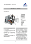
Type 8605
Digital Control Electronics for Proportional Valves
Digitale Ansteuerelektronik für Proportionalventile
Régulateur électronique numérique pour vannes proportionnelles
Quickstart
Bürkert Fluid Control Systems
Sales Center
Christian-Bürkert-Str. 13-17
D-74653 Ingelfingen
Tel. + 49 (0) 7940 - 10 91 111
Fax + 49 (0) 7940 - 10 91 448
E-mail: [email protected]
International address
www.burkert.com
Manuals and data sheets on the Internet: www.burkert.com
Bedienungsanleitungen und Datenblätter im Internet: www.buerkert.de
Manuel d'utilisation et fiches techniques sur Internet : www.buerkert.fr
© Bürkert Werke GmbH, 2008 - 2014
Operating Instructions 1407/06_EU-ML_00805637 / Original DE
www.burkert.com
1
Table of Contents
1
Quickstart...........................................................................................................................................2
2
Authorized use...............................................................................................................................3
3
Basic safety instructions.......................................................................................................4
4
General Information...................................................................................................................5
5
Product Description...................................................................................................................5
6
Technical Data...............................................................................................................................7
7
Installation.........................................................................................................................................8
8
Cleaning...........................................................................................................................................10
9
Transport..........................................................................................................................................11
10 Storage.............................................................................................................................................11
11 Disposal............................................................................................................................................11
Quickstart
Quickstart contain important information.
▶▶ Read the Quickstart carefully and follow the safety instructions.
▶▶ Keep Quickstart in a location where they are available to every user.
▶▶ The liability and warranty for the device are void if the Quickstart are
not followed.
Quickstart for Type 8605 explains, for example, how to install and startup the device. A detailed description of the device can be found in the
operating instructions for Type 8605. These instructions also include the
warranty provisions and details about the correct disposal of the device.
The operating instructions can be found on the enclosed CD
and on the Internet at: www.burkert.com
1.1 Symbols
▶▶ Designates instructions for risk prevention.
→→Designates a procedure which you must carry out.
Danger!
Immediate danger! Serious or fatal injuries.
english
2
2
Warning!
Possible danger! Serious or fatal injuries.
Caution!
Danger! Moderate or minor injuries.
Note!
Warns of damage to property.
Important tips and recommendations.
Refers to information in these operating instructions or in other
documentation.
1.2 Definitions of terms
Authorized use
Non-intended use of the device may be a hazard to people, nearby
equipment and the environment.
▶▶ The device is designed for controlling Bürkert proportional valves.
▶▶ The device must not be exposed to direct sunlight.
▶▶ Do not use the device outdoors.
▶▶ To ensure that the device functions perfectly, set the PWM frequency
which is suitable for the valve. A table of set values can be found on
the Bürkert homepage www.burkert.com → Type 8605.
▶▶ Use according to the authorized data, operating conditions and conditions of use specified in the contract documents and operating instructions. These are described in the chapter entitled “6 Technical Data”.
▶▶ The device may be used only in conjunction with third-party devices
and components recommended and authorized by Bürkert.
▶▶ Correct transportation, correct storage and installation and careful
use and maintenance are essential for reliable and faultless operation.
▶▶ Use the device only as intended.
In these instructions, the term “device” always refers to digital control
electronics for proportional valves Type 8605.
english
3
Basic safety instructions
These safety instructions do not make allowance for any contingencies
and events which may arise during assembly, operation and maintenance.
Risk of injury from high pressure!
▶▶ Before loosening the lines and valves, turn off the pressure and
vent the lines.
Risk of injury due to electrical shock!
▶▶ Before loosening the lines and valves, switch off.
▶▶ Before working on the system or device, switch off the power supply
and secure to prevent reactivation.
▶▶ Observe applicable accident prevention and safety regulations for
electrical equipment.
There is a risk of injury when the pressure drops in the system!
▶▶ Avoid pressure drops!
▶▶ Design the pressure supply system with as large a volume as possible, even with up line devices such as e. g. pressure regulators,
air conditioners, shut-off valves.
4
english
3
General hazardous situations.
To prevent injury, ensure that:
▶▶ That the system cannot be activated unintentionally.
▶▶ Installation and repair work may be carried out by authorised technicians only and with the appropriate tools.
▶▶ After an interruption in the power supply or pneumatic supply, ensure
that the process is restarted in a defined or controlled manner.
▶▶ The device may be operated only when in perfect condition and in
consideration of the operating instructions.
▶▶ The general rules of technology apply to application planning and
operation of the device.
5
Note!
Product Description
Electrostatic sensitive components / modules!
5.1 Field of application
The device contains electronic components which react sensitively to
electrostatic discharge (ESD). Contact with electrostatically charged
persons or objects is hazardous to these components. In the worst case
scenario, they will be destroyed immediately or will fail after start-up.
The Control Electronics, Type 8605, is designed for continuous operation
in industrial environments, in particular in the fields of open-loop and
closed-loop control engineering.
• Observe the requirements in accordance with EN 61340-5-1 and
5-2 to minimise or avoid the possibility of damage caused by sudden
electrostatic discharge!
• Do not touch live electronic components!
4
General Information
4.1 Warranty
The warranty is only valid if the device is used as authorized in accordance
with the specified application conditions.
5.2 General description
The Digital Control Electronics for Proportional Valves, Type 8605 (hereinafter referred to as Control Electronics, Type 8605) Controls all Bürkert
proportional valves with a max. current in the range from 40 to 2000 mA.
It transforms an external standard signal into a pulse-width modulated
voltage signal (PWM) that is supplied to the solenoid coil of the proportional valve.
A given value of the average coil current is thereby assigned to each
value of the input signal. The proportional opening of the valve can be
set via the coil current.
4.2 Information on the Internet
Operating instructions and data sheet for Type 8605 can be found on
the Internet at: www.burkert.com
english
5
5.3 Forms of the device
5.3.1 Type 8605 cable plug version
5.3.2 Type 8605 DIN rail version
Fig. 1:
Fig. 2:
Type 8605 Cable plug version
Type 8605 DIN rail version
Plug-in version on valves with connector pattern A (e. g. types 2832,
2833, 2834, 2835, 2836, 2853, 2863, 2865, 2873, 2875, 6022,
6023, 6024, 6223).
Separate electronics in housing for DIN rail mounting to DIN EN 50022.
This form is suitable for all proportional valves in the indicated current
range. The operating unit cannot be removed.
The operating unit can be removed after the setting process. During
operation of the Control Electronics 8605 in cable plug version without
operating unit, the operating status is indicated by two LEDs.
Device variants:
Device variants:
• Variant 1 for valves with a max. current from 200 to 1000 mA
• Variant 1 for valves with a max. current from 40 to 220 mA
• Variant 2 for valves with a max. current from 200 to 1000 mA
• Variant 3 for valves with a max. current from 500 to 2000 mA
• Variant 2 for valves with a max. current from 500 to 2000 mA
english
6
6
Technical Data
Current (0 ...20, 4 ... 20 mA) input impedance < 200 W
6.1 Operating Conditions
Power supply12...24 V DC ± 10%
Residual ripple 5 %
Power consumption
ca. 1 W
Output current
(on the valve)
max. 2 A
Operating temperature
-10 ... 60 ºC / 14 ...140 ºF
Interference resistance
to EN50082-2
Emission
to EN50081-2
Current range, depending
on the version for valves40 ... 220 mA,
200 ... 1000 mA,
500 ... 2000 mA
Housing: DIN rail version
Degree of protection
IP40 (DIN EN 60529)
Materials
Polyamide / PBT
Dimensions
LxWxH: 97 x 27 x 57 mm
Housing: Cable plug version
Degree of protection
IP65 (DIN EN 60529)
Materials
Polyamide / PC
Dimensions
LxWxH: 70 x 32 x 42.5 mm
Standard signal input
Voltage (0 ... 5, 0 ... 10 V)
input impedance > 20 kW
english
7
7
Installation
7.2 Electrical connections
7.2.1 Type 8605 cable plug version
7.1 Safety instructions
Type 8605 with cable plug version is connected electrically via a 4-pin
terminal strip in the device.
Danger!
Risk of injury from high pressure in the equipment!
▶▶ Before loosening the pipes and valves, turn off the pressure and vent
the lines.
Risk of injury due to electrical shock!
▶▶ Before reaching into the device or the equipment, switch off the power
supply and secure to prevent reactivation.
▶▶ Observe applicable accident prevention and safety regulations for
electrical equipment.
Cable diameter
6 ... 8 mm
Cable cross-section
max. 0.75 mm2
Cable connections
Cable gland or plug-in connector M12,
4-pin
Standard signal (+)
Standard signal (-)
Warning!
Risk of injury from improper installation!
▶▶ Installation may be carried out by authorized technicians only and with
the appropriate tools.
Risk of injury from unintentional activation of the system and an
uncontrolled restart!
▶▶ Secure system from unintentional activation.
▶▶ Following assembly, ensure a controlled restart.
Fig. 3:
Terminal strip connection
english
8
12 ... 24 V DC
Standard signal (+)
GND
Fig. 4:
GND
12 ... 24 V DC
Note!
Ensure proper seating of the valve when screwing onto the valve (cable
plug version).
Do not tighten the screw M3 too tightly (max. 0.3 Nm), as otherwise
the housing will be deformed and proper operation of the keys will no
longer be possible.
Standard signal (-)
Plug connector connection
7.2.2 LEDs during operation without operating unit
During operation of the control electronics Type 8605 cable plug version
without operating unit, the operating status is indicated by two LEDs.
LED green: Device in operation
LED yellow: Current through valve
Tighten screw M3 to max. 0.3 Nm
Fig. 5:
Fig. 6:
Assembly at the valve
LEDs for version without operating unit
english
7.2.3 Type 8605 DIN rail version
Legend to figure:
The electrical connection of Type 8605 DIN rail version is made via
terminal strips.
Terminal strip
Cable
cross-section
2-pin
For valve
max. 1.5 mm2
3-pin
For RS232 or RS485 interface
max. 0.5 mm2
4-pin
For voltage supply and standard
signal
max. 1.5 mm2
5
6
7
8
9
1
2
3
4
Fig. 7:
10
Terminal strip connection
english
9
1
2
3
4
5
8
12 ... 24 V DC
GND
Standard signal (-)
Standard signal (+)
Valve
6
7
8
9
Valve
RS485-B / TxD
RS485-A / RxD
GND
Cleaning
Use the normal cleaning agents to clean the Control Electronics, Type
8605. Use no alkaline cleansing agents, as these have a damaging effect
on the materials used.
9
Transport
Note!
Transport damages!
Inadequately protected equipment may be damaged during transport.
• During transportation protect the device against wet and dirt in
shock-resistant packaging.
• Avoid exceeding or dropping below the allowable storage
temperature.
10
Storage
Note!
Incorrect storage may damage the device.
• Store the device in a dry and dust-free location!
• Storage temperature. -40 - + 55 °C.
10.1 Decommissioning
→→Switch off the power supply.
→→Remove the Control Electronics.
→→Keep the control electronics in the original packaging or in some
other suitable packaging.
10.2 Restarting
Switch on the Control Electronics Type 8605 again as follows:
→→Unpack the Control Electronics and allow it to reach room temperature
before switching on again.
→→Then proceed as described in chapter “7 Installation”.
11
Disposal
Note!
Damage to the environment caused by device components contaminated with media.
• Dispose of the device and packaging in an environmentally friendly
manner.
• Observe applicable regulations on disposal and the environment.
Switch off the Control Electronics Type 8605 as follows:
→→Depressurize the system.
english
11
Type 8605
Digital Control Electronics for Proportional Valves
Digitale Ansteuerelektronik für Proportionalventile
Régulateur électronique numérique pour vannes proportionnelles
Quickstart
Bürkert Fluid Control Systems
Sales Center
Christian-Bürkert-Str. 13-17
D-74653 Ingelfingen
Tel. + 49 (0) 7940 - 10 91 111
Fax + 49 (0) 7940 - 10 91 448
E-mail: [email protected]
International address
www.burkert.com
Manuals and data sheets on the Internet: www.burkert.com
Bedienungsanleitungen und Datenblätter im Internet: www.buerkert.de
Manuel d'utilisation et fiches techniques sur Internet : www.buerkert.fr
© Bürkert Werke GmbH, 2008 - 2014
Operating Instructions 1407/06_EU-ML_00805637 / Original DE
www.burkert.com
1
Inhaltsverzeichnis
1
Quickstart........................................................................................................................................12
2
Bestimmungsgemäße Verwendung..........................................................................13
3
Grundlegende Sicherheitshinweise..........................................................................14
4
Allgemeine Hinweise.............................................................................................................15
5
Systembeschreibung.............................................................................................................15
6
Technische Daten....................................................................................................................17
7
Montage....................................................................................................................................................18
8
Reinigung........................................................................................................................................20
9
Transport..........................................................................................................................................21
10 Lagerung.........................................................................................................................................21
11 Entsorgung....................................................................................................................................21
Quickstart
Quickstart enthält wichtige Informationen.
▶▶ Quickstart sorgfältig lesen und Hinweise zur Sicherheit beachten.
▶▶ Quickstart muss jedem Benutzer zur Verfügung stehen.
▶▶ Haftung und Gewährleistung für das Gerät entfällt, wenn die Anweisungen des Quickstarts nicht beachtet werden.
Der Quickstart erläutert beispielhaft die Montage und Inbetriebnahme
des Geräts.
Die ausführliche Beschreibung des Geräts finden Sie in der Bedienungsanleitung für den Typ 8605.
Die Bedienungsanleitung finden Sie auf der beigelegten CD
oder im Internet unter: www.buerkert.de
1.1 Darstellungsmittel
▶▶ markiert eine Anweisung zur Gefahrenvermeidung.
→→markiert einen Arbeitsschritt den Sie ausführen müssen.
Gefahr!
Unmittelbare Gefahr! Schwere oder tödlichen Verletzungen.
deutsch
12
2
Warnung!
Mögliche Gefahr! Schwere oder tödlichen Verletzungen.
Vorsicht!
Gefahr! Mittelschwere oder leichten Verletzungen.
Hinweis!
Warnt vor Sachschäden.
Wichtige Tipps und Empfehlungen.
verweist auf Informationen in dieser Bedienungsanleitung oder
in anderen Dokumentationen.
1.2 Begriffsdefinition Gerät
Der in dieser Anleitung verwendeten Begriff „Gerät“ steht immer für
digitale Ansteuerelektronik für Proportionalventile Typ 8605.
BestimmungsgemäSSe
Verwendung
Bei nicht bestimmungsgemäßem Einsatz können Gefahren für
Personen, Anlagen in der Umgebung und die Umwelt entstehen.
▶▶ Der Typ 8605 ist für die Ansteuerung von Bürkert Proportionalventilen
konzipiert.
▶▶ Das Gerät nicht der direkten Sonneneinstrahlung aussetzen.
▶▶ Das Gerät nicht im Außenbereich einsetzen.
▶▶ Damit das Gerät einwandfrei funktioniert muss die zum Ventil passende
PWM-Frequenz eingestellt werden. Die Tabelle mit den Einstellwerten
finden Sie auf der Bürkert Homepage www.buerkert.de → Typ 8605.
▶▶ Für den Einsatz die in den Vertragsdokumenten und der Bedienungsanleitung spezifizierten zulässigen Daten, Betriebs- und Einsatzbedingungen beachten. Diese sind im Kapitel „6 Technische Daten“
beschrieben.
▶▶ Das Gerät nur in Verbindung mit von Bürkert empfohlenen bzw. zugelassenen Fremdgeräten und -komponenten einsetzen.
▶▶ Voraussetzungen für den sicheren und einwandfreien Betrieb sind
sachgemäßer Transport, sachgemäße Lagerung und Installation sowie
sorgfältige Bedienung und Instandhaltung.
▶▶ Das Gerät nur bestimmungsgemäß einsetzen.
deutsch
3
Grundlegende
Sicherheitshinweise
Diese Sicherheitshinweise berücksichtigen keine Zufälligkeiten und
Ereignisse, die bei Montage, Betrieb und Wartung auftreten können.
Gefahr durch hohen Druck!
▶▶ Vor dem Lösen von Leitungen und Ventilen den Druck abschalten
und Leitungen entlüften.
Gefahr durch elektrische Spannung!
▶▶ Vor dem Lösen von Leitungen und Ventilen spannungslos schalten.
▶▶ Vor Eingriffen in das Gerät oder die Anlage Spannung abschalten
und vor Wiedereinschalten sichern.
▶▶ Die geltenden Unfallverhütungs- und Sicherheitsbestimmungen für
elektrische Geräte beachten.
Bei abfallendem Druck im System besteht Verletzungsgefahr!
▶▶ Druckabfall vermeiden.
▶▶ Druckversorgung möglichst großvolumig ausführen, auch bei vorgeschalteten Geräten wie z. B. Druckreglern, Wartungseinheiten,
Absperrventilen.
14
deutsch
13
Allgemeine Gefahrensituationen.
Zum Schutz vor Verletzungen ist zu beachten:
▶▶ Dass die Anlage nicht unbeabsichtigt betätigt werden kann.
▶▶ Installations- und Instandhaltungsarbeiten dürfen nur von autorisiertem
Fachpersonal mit geeignetem Werkzeug ausgeführt werden.
▶▶ Nach einer Unterbrechung der elektrischen oder pneumatischen
Versorgung ist ein definierter oder kontrollierter Wiederanlauf des
Prozesses zu gewährleisten.
▶▶ Das Gerät darf nur in einwandfreiem Zustand und unter Beachtung
der Bedienungsanleitung betrieben werden.
▶▶ Für die Einsatzplanung und den Betrieb des Gerätes müssen die
allgemeinen Regeln der Technik eingehalten werden.
4.2 Informationen im Internet
Hinweis!
Elektrostatisch gefährdete Bauelemente / Baugruppen!
Das Gerät enthält elektronische Bauelemente, die gegen elektrostatische Entladung (ESD) empfindlich reagieren. Berührung mit elektrostatisch aufgeladenen Personen oder Gegenständen gefährdet diese
Bauelemente. Im schlimmsten Fall werden sie sofort zerstört oder fallen
nach der Inbetriebnahme aus.
• Beachten Sie die Anforderungen nach EN 61340-5-1 und 5-2, um
die Möglichkeit eines Schadens durch schlagartige elektrostatische
Entladung zu minimieren bzw. zu vermeiden!
• Elektronische Bauelemente nicht bei anliegender Versorgungsspannung berühren!
4
Allgemeine Hinweise
4.1 Gewährleistung
Voraussetzung für die Gewährleistung ist der bestimmungsgemäße
Gebrauch des Typs 8605 unter Beachtung der spezifizierten
Einsatzbedingungen.
Bedienungsanleitungen und Datenblätter zum Typ 8605 finden Sie im
Internet unter: www.buerkert.de
5
Systembeschreibung
5.1 Vorgesehener Einsatzbereich
Der Typ 8605 ist für den dauerhaften Einsatz in Industrieumgebung
konzipiert, insbesondere in den Bereichen der Steuer- und Regeltechnik.
5.2 Allgemeine Beschreibung
Die Digitale Ansteuerelektronik für Proportionalventile Typ 8605 (im
Folgenden Ansteuerelektronik Typ 8605 genannt) steuert alle Bürkert Proportionalventile mit einem Maximalstrom im Bereich von 40 ... 2000 mA.
Sie wandelt ein externes Normsignal in ein pulsweitenmoduliertes
Spannungssignal (PWM) um, mit dem die Magnetspule des Proportionalventils beaufschlagt wird. Jedem Wert des Eingangssignals ist dabei
ein bestimmter Wert des mittleren Spulenstroms zugeordnet. Über den
Spulenstrom ist die Öffnung des Ventils proportional einstellbar.
deutsch
15
5.3 Bauformen des Geräts
5.3.1 Typ 8605 Gerätesteckdoseausführung
5.3.2 Typ 8605 Hutschienenausführung
Bild 1: Typ 8605 Gerätesteckdoseausführung
Bild 2: Typ 8605 Hutschienenausführung
Aufsteckbare Version auf Ventile mit Steckerbild A (zum Beispiel die Typen:
2832, 2833, 2834, 2835, 2836, 2853, 2863, 2865, 2873, 2875, 6022,
6023, 6024, 6223).
Die Bedieneinheit kann nach dem Einstellvorgang abgenommen werden.
Bei Betrieb der Ansteuerelektronik 8605 in Gerätesteckdoseausführung
ohne Bedieneinheit wird der Betriebszustand durch zwei LEDs angezeigt.
Separate Elektronik in Gehäuse für Hutschienenmontage nach DIN EN
50022. Diese Bauform eignet sich für alle Proportionalventile im angegebenen Strombereich. Die Bedieneinheit ist nicht abnehmbar.
Gerätevarianten:
• Variante 1 für Ventile mit einem Maximalstrom von 40 ... 220 mA
Gerätevarianten:
• Variante 2 für Ventile mit einem Maximalstrom von 200 ... 1000 mA
• Variante 1 für Ventile mit einem Maximalstrom von 200...1000 mA
• Variante 3 für Ventile mit einem Maximalstrom von 500 ... 2000 mA
• Variante 2 für Ventile mit einem Maximalstrom von 500...2000 mA
deutsch
16
6
Technische Daten
Gehäuse: Hutschienenausführung
6.1 Betriebsbedingungen
Schutzart
IP40 (DIN EN 60529)
Spannungsversorgung12...24 V DC ±10 %
Restwelligkeit 5 %
Werkstoffe
Polyamid / PBT
Maße
LxBxH: 97 x 27 x 57 mm
Leitungsaufnahme
ca. 1 W
Ausgangsstrom (zum Ventil) max. 2 A
Betriebstemperatur
-10 ... 60 ºC / 14 ...140 ºF
Störfestigkeit
nach EN50082-2
Störausstrahlung
nach EN50081-2
Gehäuse: Gerätesteckdoseausführung
Schutzart
IP65 (DIN EN 60529)
Werkstoffe
Polyamid / PC
Maße
LxBxH: 70 x 32 x 42,5 mm
Strombereich je nach
Ausführung für Ventile40 ... 220 mA,
200 ... 1000 mA,
500 ... 2000 mA
Normsignaleingang
Spannung (0 ... 5, 0 ... 10 V) Eingangimpedanz > 20 kW
Strom (0 ...20, 4 ... 20 mA)
Eingangimpedanz <200 W
deutsch
17
7
Montage
7.2 Elektrische Anschlüsse
7.2.1 Typ 8605 Gerätesteckdoseausführung
7.1 Sicherheitshinweise
Typ 8605 mit Gerätesteckdoseausführung wird über eine 4-polige
Klemmleiste im Gerät elektrisch angeschlossen.
Gefahr!
Verletzungsgefahr durch hohen Druck in der Anlage!
▶▶ Vor dem Lösen von Leitungen oder Ventilen den Druck abschalten
und Leitungen entlüften.
Verletzungsgefahr durch Stromschlag!
▶▶ Vor Eingriffen in das Gerät oder die Anlage Spannung abschalten
und vor Wiedereinschalten sichern!
▶▶ Die geltenden Unfallverhütungs- und Sicherheitsbestimmungen für
elektrische Geräte beachten!
Kabel-Durchmesser
6 ... 8 mm
Kabel-Querschnitt
max. 0,75 mm2
Kabel-Anschlüsse
Kabelverschraubung oder Steckverbinder
M12, 4-polig
Normsignal (+)
Normsignal (-)
Warnung!
Verletzungsgefahr bei unsachgemäßer Montage!
▶▶ Die Montage darf nur autorisiertes Fachpersonal mit geeignetem
Werkzeug durchführen!
Verletzungsgefahr durch ungewolltes Einschalten der Anlage
und unkontrollierten Wiederanlauf!
▶▶ Anlage vor unbeabsichtigtem Betätigen sichern.
▶▶ Nach der Montage einen kontrollierten Wiederanlauf gewährleisten.
GND
12 ... 24 V DC
Bild 3: Anschluss Klemmleiste
deutsch
18
12 ... 24 V DC
GND
Hinweis!
Normsignal (+)
Beim Verschrauben mit dem Ventil (Gerätesteckdoseausführung) auf
einwandfreien Sitz der Dichtung achten.
Die Schraube M3 nicht zu fest anziehen (max. 0,3 Nm), da sich das
Gehäuse sonst verformt und eine einwandfreie Bedienung der Tasten
nicht mehr gewährleistet ist.
Normsignal (-)
Bild 4: Anschluss Steckverbinder
7.2.2 LEDs bei Betrieb ohne Bedieneinheit
Bei Betrieb der Ansteuerelektronik Typ 8605 Gerätesteckdoseausführung
ohne Bedieneinheit wird der Betriebszustand durch zwei LEDs angezeigt.
LED grün: Gerät in Betrieb
LED gelb: Strom durch Ventil
Schraube M3 mit max. 0,3 Nm anziehen
Bild 6: LEDs bei Ausführungen ohne Bedieneinheit
Bild 5: Typ 8605 - Montage an das Ventil
deutsch
7.2.3 Typ 8605 Hutschienenausführung
Legende:
Typ 8605 Hutschienenausführung wird über Klemmleisten elektrisch
angeschlossen.
2-polig
3-polig
4-polig
Klemmleiste
Für Ventil
Für RS232- bzw.
RS485-Schnittstelle
Für Spannungsversorgung
und Normsignal
1
2
3
4
Kabel-Querschnitt
max. 1,5 mm2
max. 0,5 mm2
max. 1,5 mm2
5
6
7
8
9
Bild 7: Anschluss Klemmleiste
20
19
deutsch
1
2
3
4
5
8
12 ... 24 V DC
GND
Normsignal (-)
Normsignal (+)
Ventil
6
7
8
9
Ventil
RS485-B/T x D
RS485-A/R x D
GND
Reinigung
Die Ansteuerelektronik Typ 8605 mit den üblichen Reinigungsmitteln
reinigen. Keine alkalischen Reiniger verwenden, da diese schädigende
Auswirkungen auf die verwendeten Werkstoffe haben.
9
Transport
Hinweis!
Transportschäden!
Unzureichend geschützte Geräte können durch den Transport
beschädigt werden.
• Gerät vor Nässe und Schmutz geschützt in einer stoßfesten Verpackung transportieren.
• Eine Über- bzw. Unterschreitung der zulässigen Lagertemperatur
vermeiden.
10.1 Außerbetriebnahme
Setzen Sie die Ansteuerelektronik Typ 8605 wie folgt außer Betrieb:
→→Das System entlüften.
→→Die Spannungsversorgung abschalten
→→Die Ansteuerelektronik demontieren
→→Die Ansteuerelektronik in der Originalverpackung oder einer
anderen geeigneten Verpackung aufbewahren.
10.2 Wieder-Inbetriebnahme
Nehmen Sie die Ansteuerelektronik Typ 8605 wie folgt wieder in Betrieb:
→→Die
10
Lagerung
Hinweis!
Falsche Lagerung kann Schäden am Gerät verursachen.
• Gerät trocken und staubfrei lagern!
• Lagertemperatur: -40 …+ 55 °C
Ansteuerelektronik vor der Wieder-Inbetriebnahme entpacken
und aklimatisieren.
→→Danach wie im Kapitel „7 Montage“ beschrieben vorgehen.
11
Entsorgung
Hinweis!
Umweltschäden durch von Medien kontaminierte Geräteteile.
• Geltende Entsorgungsvorschriften und Umweltbestimmungen einhalten.
• Nationale Abfallbeseitigungsvorschriften beachten.
deutsch
21
Type 8605
Digital Control Electronics for Proportional Valves
Digitale Ansteuerelektronik für Proportionalventile
Régulateur électronique numérique pour vannes proportionnelles
Quickstart
Bürkert Fluid Control Systems
Sales Center
Christian-Bürkert-Str. 13-17
D-74653 Ingelfingen
Tel. + 49 (0) 7940 - 10 91 111
Fax + 49 (0) 7940 - 10 91 448
E-mail: [email protected]
International address
www.burkert.com
Manuals and data sheets on the Internet: www.burkert.com
Bedienungsanleitungen und Datenblätter im Internet: www.buerkert.de
Manuel d'utilisation et fiches techniques sur Internet : www.buerkert.fr
© Bürkert Werke GmbH, 2008 - 2014
Operating Instructions 1407/06_EU-ML_00805637 / Original DE
www.burkert.com
1
Table des matières
1
Quickstart........................................................................................................................................22
2
Utilisation conforme...............................................................................................................23
3
Consignes de sécurité fondamentales...................................................................24
4
Indications Générales...........................................................................................................25
5
Description du Système......................................................................................................25
6
Caractéristiques techniques............................................................................................27
7
Installation................................................................................................................................................28
8
Nettoyage.......................................................................................................................................30
9
Transport..........................................................................................................................................31
10 Stockage.........................................................................................................................................31
11 Élimination......................................................................................................................................31
Quickstart
Quickstart contiennent des informations importantes.
▶▶ Lire attentivement quickstart et respecter les consignes de sécurité.
▶▶ Quickstart doit être à disposition de chaque utilisateur.
▶▶ Nous déclinons toute responsabilité et n’accordons aucune garantie
légale pour l’appareil en cas de non-respect des instructions figurant dans quickstart.
Le démarrage rapide explique de manière exemplaire le montage et la
mise en service de l’appareil.
La description complète de l’appareil est fournie dans les instructions de
service pour le type 8605.
Les instructions de service se trouvent sur le CD ci-joint ou sur
Internet sous : www.buerkert.fr
1.1 Symboles
▶▶ identifie une consigne pour éviter un danger.
→→Identifie une opération que vous devez effectuer.
Danger !
Danger imminent ! Blessures graves ou mortelles.
français
22
2
Avertissement !
Danger potentiel ! Blessures graves ou mortelles.
Attention !
Danger ! Blessures légères ou de moyenne gravité.
Remarque !
Met en garde contre des dommages matériels.
Conseils et recommandations importants.
renvoie à des informations dans ce manuel d'utilisation ou dans
d'autres documentations.
1.2 Définition des termes
Le terme « appareil » utilisé dans ces instructions désigne toujours le
régulateur électronique numérique pour vannes proportionnelles type
8605.
Utilisation conforme
L’utilisation non conforme du type 8605 peut présenter des dangers
pour les personnes, les installations proches et l’environnement.
▶▶ L‘appareil est conçu pour la commande de Bürkert vannes
proportionnelles.
▶▶ L‘appareil ne doit pas être exposé au rayonnement solaire direct.
▶▶ L’appareil ne doit pas être installé et utilisé en plein air.
▶▶ Il convient de régler la fréquence MLI adaptée à la vanne pour garantir
le fonctionnement parfait de l’appareil. Vous trouverez le tableau avec
les valeurs de réglage sur la page d’accueil Bürkert www.buerkert.fr
→ Type 8605.
▶▶ L‘utilisation doit se faire dans le respect des données admissibles
spécifiées dans les documents contractuels et les instructions de
service ainsi que des conditions d‘exploitation et d‘utilisation décrites
au chapitre « 6 Caractéristiques techniques ».
▶▶ L’appareil peut être utilisé uniquement en association avec les
appareils et composants étrangers recommandés et homologués
par Bürkert.
▶▶ Les conditions pour l’utilisation sûre et parfaite sont un transport,
un stockage et une installation dans les règles ainsi qu’une parfaite
utilisation et maintenance.
▶▶ Veillez à ce que l‘utilisation du types 8605 soit toujours conforme.
français
3
Consignes de sécurité
fondamentales
Ces consignes de sécurité ne tiennent pas compte des hasards et des
événements pouvant survenir lors du montage, de l’exploitation et de
l’entretien.
Danger avec haute pression.
▶▶ Avant de desserrer les tuyauteries et les vannes, coupez la pression
et purgez les conduites.
Danger présenté par la tension électrique.
▶▶ Avant de desserrer les tuyauteries et les vannes, mettez hors tension.
▶▶ Avant d’intervenir dans l’appareil ou l’installation, coupez la tension
et empêchez toute remise sous tension par inadvertance.
▶▶ Veuillez respecter les réglementations en vigueur pour les appareils
électriques en matière de prévention des accidents ainsi qu’en
matière de sécurité.
La pression dans le système peut chuter lors des commutations!
▶▶ Empêcher la chute de pression.
▶▶ Concevoir une alimentation en pression du plus grand volume possible, y compris pour les appareils en amont comme les régulateurs de
pression, les unités de maintenance, les vannes d’arrêt, par exemple.
24
23
Situations dangereuses d’ordre général.
Pour prévenir les blessures, respectez ce qui suit :
▶▶ L’installation ne peut pas être actionnée par inadvertance.
▶▶ Les travaux d’installation et de maintenance doivent être effectués
uniquement par des techniciens qualifiés et habilités disposant de
l’outillage approprié.
▶▶ Après une interruption de l’alimentation électrique ou du fluide, un
redémarrage défini ou contrôlé du process doit être garanti.
▶▶ L’appareil doit être utilisé uniquement en parfait état et en respectant les instructions de service.
▶▶ Les règles générales de la technique sont à appliquer pour l’opérationnel et l’utilisation de l’appareil.
français
4.2 Informations sur Internet
Remarque !
Éléments/sous-groupes sujets aux risques électrostatiques !
• L’appareil contient des éléments électroniques sensibles aux
décharges électrostatiques (ESD). Ces éléments sont affectés
par le contact avec des personnes ou des objets ayant une charge
électrostatique. Au pire, ils sont immédiatement détruits ou tombent
en panne après mise en service.
• Respectez les exigences selon DIN EN 61340-5-1 / 5-2 pour minimiser ou éviter la possibilité d’un dommage causé par une soudaine
décharge électrostatique !
• Ne pas toucher les composants électroniques lorsque la tension
d’alimentation est présente !
4
Indications Générales
4.1 Garantie légale
La condition pour bénéficier de la garantie légale est l’utilisation conforme
du type 8605 dans le respect des conditions d’utilisation spécifiées.
Vous trouverez sur Internet les instructions de service et fiches techniques
relatives au type 8605 : www.buerkert.fr
5
Description du Système
5.1 Domaine d’utilisation
Le régulateur électronique de type 8605 est conçu pour une utilisation
durable dans un environnement industriel, notamment dans les domaines
des techniques de commande et de régulation.
5.2 Description générale
Le régulateur électronique numérique pour vannes proportionnelles de
type 8605 (ci-après Régulateur électronique de type 8605) est conçu
pur la régulation de toutes les vannes proportionnelles Bürkert avec
une max. courant allant de 40 à 2000 mA.
Il transforme un signal normalisé externe en un signal de tension avec
modulation de largeur d’impulsions (MLI), appliqué à la bobine d’électroaimant de la vanne proportionnelle. Une certaine valeur du courant de
bobine moyen est attribuée à chaque valeur du signal d’entrée. L’ouverture
de la vanne est réglable en proportion via le courant de bobine.
français
25
5.3 Forme de l’appareil
5.3.1 Type 8605 exécution connecteur
5.3.2 Type 8605 exécution profilé chapeau
Fig. 1 :
Fig. 2 :
Type 8605 exécution connecteur
Type 8605 exécution profilé chapeau
Exécution enfichable sur vannes avec schéma de connexion A (par ex.
types 2832, 2833, 2834, 2835, 2836, 2853, 2863, 2865, 2873, 2875,
6022, 6023, 6024, 6223).
Système électronique séparé dans le boîtier pour montage en profilé
chapeau selon la norme DIN EN 50022. Cette forme convient pour
toutes les vannes proportionnelles dans la plage de puissance indiquée.
Dans le cas de l’utilisation du régulateur électronique 8605 en exécution
avec connecteur sans unité de commande, le mode de service est indiqué
par deux LED.
Variantes :
Variantes :
• Variante 1 pour vannes avec une max. courant de 40 - 220 mA,
• Variante 2 pour vannes avec une max. courant de 200 - 1000 mA,
• Variante 3 pour vannes avec une max. courant de 500 - 2000 mA.
Deux variantes sont disponibles:
• Variante 1 pour vannes avec une max. courant de 200 - 1000 mA,
• Variante 2 pour vannes avec une max. courant de 500 - 2000 mA.
français
26
6
Caractéristiques techniques
Intensité (0 ... 20, 4 ... 20 mA) Impédance d’entrée < 200 W
6.1 Conditions d‘exploitation
Boîtier exécution profilé chapeau
Alimentation de tension12...24 V DC ± 10%
Ondulation résiduelle 5 %
Puissance absorbée
(sans vanne)
Courant de sortie
(vers la vanne)
ca. 1 W
Degré de protection selon
IP40 (DIN EN 60529)
Matériaux
Polyamide / PBT
Dimensions
LxLxH : 97 x 27 x 57 mm
max. 2 A
Température de service-10 ... 60 ºC / 14 ... 140 ºF
Boîtier exécution connecteur
Immunité au brouillage
selon EN50082-2
Degré de protection selon
IP65 (DIN EN 60529)
Émissions parasites
selon EN50081-2
Matériaux
Polyamide / PC
Dimensions
LxLxH : 70 x 32 x 42,5 mm
Plage de max. courant
pour les vannes40 ... 220 mA,
200 ... 1000 mA,
500 ... 2000 mA
Signal d’entrée normalisé
Tension (0 ... 5, 0 ... 10 V) Impédance d’entrée > 20 kW
français
27
7
Installation
7.1 Consignes de sécurité
7.2 Branchements électriques
7.2.1 Type 8605 exécution le connecteur
Danger !
Risque de blessures avec présence de haute pression dans
l’installation.
▶▶ Avant de desserrer les tuyauteries et les vannes, coupez la pression et
purgez les conduites.
Risque de choc électrique.
▶▶ Avant d’intervenir dans l’appareil ou l’installation, coupez la tension et
empêchez toute remise sous tension par inadvertance.
▶▶ Veuillez respecter les réglementations en vigueur pour les appareils
électriques en matière de prévention des accidents ainsi qu’en matière
de sécurité.
Le raccordement électrique du type 8605 avec exécution connecteur se
fait au moyen d’une borne plate à 4-pôles.
Câble diamètre
6 ... 8 mm
Câble section
max. 0,75 mm2
Raccords câbles
Raccord à vis pour câble ou connecteur
M12, 4-pôles
Signal normalisé (+)
Signal normalisé (-)
Avertissement !
Risque de blessures pour montage non conforme.
▶▶ Le montage doit être effectué uniquement par un personnel qualifié
et habilité disposant de l’outillage approprié.
Risque de blessures dû à la mise en marche involontaire de
l’installation et le redémarrage non contrôlé.
▶▶ Empêchez tout actionnement involontaire de l’installation.
▶▶ Garantissez un redémarrage contrôlé après le montage.
GND
12 ... 24 V DC
Fig. 3 :
français
28
12 ... 24 V DC
GND
Fig. 4 :
Raccordement sur la borne plate
Remarque !
Signal normalisé (+)
En vissant le raccord avec la vanne (exécution connecteur), s’assurer
de la position correcte des joints.
Ne pas serrer la vis M3 trop fort (0,3 Nm maximum), car sinon le boîtier
risque de se déformer et le fonctionnement correct des touches ne
sera plus garanti.
Signal normalisé (-)
Raccordement sur le connecteur
7.2.2 LED sans unité de commande
Lorsque l’électronique de commande du type 8605 avec connecteur est
utilisée sans unité de commande, l’état de fonctionnement est signalé
par deux LED.
LED verte : L’appareil en service
LED jaune : Courant par la vanne
Serrer la vis M3 avec 0,3 Nm maximum
Fig. 5 :
Fig. 6 :
Montage de l’exécution connecteur sur la vanne
LED pour versions sans unité de commande
français
7.2.3 Type 8605 exécution profilé chapeau
Le branchement électrique du régulateur de type 8605 en exécution
profilé chapeau se fait au moyen de bornes plates.
Borne plate
2-pôles Pour vanne
3-pôles Pour interface RS232 ou
RS485
4-pôles Pour alimentation de tension et
signal normalisé
1
2
3
4
Fig. 7 :
30
Section de câble
max. 1,5 mm2
max. 0,5 mm2
max. 1,5 mm2
5
6
7
8
9
29
Légende :
1
2
3
4
5
8
12 ... 24 V DC
GND
Signal normalisé (-)
Signal normalisé (+)
Vanne
6
7
8
9
Vanne
RS485-B/T x D
RS485-A/R x D
GND
Nettoyage
Utiliser les produits de nettoyage habituels pour le nettoyage du régulateur
électronique de type 8605. Ne pas utiliser de détergents alcalins, car ils
attaquent les matières utilisées.
Raccordement sur la borne plate
français
9
Transport
Remarque !
Dommages dus au transport !
Les appareils insuffisamment protégés peuvent être endommagés
pendant le transport.
• Transportez l’appareil à l’abri de l’humidité et des impuretés et dans
un emballage résistant aux chocs.
• Évitez le dépassement vers le haut ou le bas de la température de
stockage admissible.
10
→→Purger le système.
→→Couper la tension d’alimentation.
→→Démonter le régulateur électronique de type 8605.
→→Conserver le régulateur électronique dans son emballage d’origine
ou dans un autre emballage approprié.
10.2 Remise en service
Remettre le régulateur électronique de type 8605 en service de la manière
suivante :
→→Déballer et acclimater le régulateur électronique de type 8605 avant
la remise en service.
→→Procéder ensuite comme indiqué dans le chapitre « 7 Installation ».
Stockage
Remarque !
11
Un mauvais stockage peut endommager l’appareil.
Élimination
Remarque !
• Stockez l’appareil au sec et à l’abri des poussières !
• Température de stockage : -40 … +55 °C.
10.1 Mise hors service
Mettre le régulateur électronique de type 8605 hors service de la manière
suivante :
français
Dommages sur l’environnement causés par des pièces d’appareil contaminées par des fluides.
▶▶ Éliminer l’appareil et l’emballage dans le respect de l’environnement.
▶▶ Respecter les prescriptions en matière d’élimination des déchets et
de protection de l’environnement en vigueur.
31