1
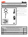
MERCEDES BENZ VITO
108 CDI - 2.200 TD
(Motore/Moteur/Engine/Motor/Motor OM611A)
110 / 112 CDI - 2.200 TD
(Motore/Moteur/Engine/Motor/Motor OM611LA)
" Abbinamento con DIAVIA FRIGO "
" Assemblage avec DIAVIA FRIGO "
" In combination with DIAVIA FRIGO "
" Mit DIAVIA FRIGO verbunden "
" Acoplamiento con DIAVIA FRIGO "
Codice/Code: 1ZFMB002E
Istruzioni montaggio
condizionatore d’aria
Instructions pour monter le
conditionneur d’air
Air conditioning
installation instructions
Klimaanlage
Einbauanleitungen
Instrucciones para el montaje
del equipo aire acondicionado
DELPHI ITALIA AUTOMOTIVE SYSTEMS S.r.l. "Stabilimento Molinella"
Via Nobili, 2 40062 Molinella (Bologna) - Italy
Telefono (0039) 051.6906111 - Fax (0039) 051.6906287 - Email: [email protected]
PRESCRIZIONI PER IL MONTAGGIO DELL' IMPIANTO A/C DIAVIA OBBLIGATORIE PER IL TECNICO INSTALLATORE, IL QUALE, NEL CASO DI LORO INOSSERVANZA, SARA' DIRETTAMENTE ED ESCLUSIVAMENTE RESPONSABILE VERSO IL CLIENTE.
1. verificare il corretto serraggio della bulloneria fornita e rimossa e comunque di tutte le parti interessate al montaggio dell' impianto A/C;
2. verificare che non vi siano perdite d' acqua, olio e aria su motore, freni, servosterzo, servofreno, ecc.;
3. verificare tutti i livelli dei liquidi. Qualora venga rimosso il radiatore acqua, ricaricare nel circuito lo stesso liquido scarico e, se è necessario un rabbocco, aggiungere
il liquido anticongelante prescritto. Assicurarsi inoltre che lo spurgo aria sia fatto come prescritto dal costruttore;
4. accertarsi della giusta tensione di tutte le cinghie, e verificare lo stato di usura di quelle non sostituite;
5. verificare che non si abbiano interferenze critiche in qualunque condizione di funzionamento. In particolare accertarsi che siano garantite distanze di sicurezza fra
tutti i particolari soggetti a movimento relativo.
6. garantirsi che non si abbiano fregamenti con conseguente usura tra le parti mediante un corretto serraggio e posizionamento delle stesse;
7. assicurarsi del corretto isolamento elettrico, della corretta installazione dei fusibili e di tutte le parti dell' impianto elettrico;
8. dopo aver effettuato la carica del refrigerante effettuare una accurata ricerca di eventuali perdite di gas;
9. eseguire comunque ogni operazione secondo norme di buona tecnica;
10. se durante l' operazione di installazione dell' impianto, vengono praticati fori o tagli, è obbligatorio proteggere tali parti con prodotto antiruggine fornito con l' impianto.
PRESCRIPTIONS POUR LE MONTAGE DE L’EQUIPEMENT A/C DIAVIA A RESPECTER PAR LE TECHNICIEN INSTALLATEUR, CAR S’IL NE LES OBSERVAIT
PAS, IL SERAIT DIRECTEMENT ET EXCLUSIVEMENT RESPONSABLE EVERS LE CLIENT.
1. vérifier que la visserie fournie ou manipulée ainsi que toutes les parties concernées par le montage de l’équipement A/C sont serrées et fixées correctement;
2. vérifier qu’il n’y a pas des fuites d’eau, d’huile ou d’air sur le moteur, les freins, la servodirection, le servofrein, etc..;
3. vérifier tous les niveaux. Si un complément de liquide de refroidissement est à effectuer, utiliser le même liquide que celui qui est dans le circuit. Si le circuit a été
vidangé, faire le plein avec le liquide préconisé par le constructeur.
4. s’assurer que la tension des courroies est correcte et vérifier l’état d’usure de celles qui n’on pas été remplacées;
5. vérifier qu’il n’ y a pas d’interférence critique dans toutes les conditions de fonctionnement. S’assurer en particulier que les distances de sécurité entre toutes les
pièces sujettes à un mouvement relatif sont respectées;
6. s’assurer qu’il n’y a pas de frottement provoquant l’usure entre les parties à cause d’un défaut de serrage ou de positionnement de celles-ci;
7. s’assurer que l’isolation électrique, l’ installation des fusibles et de toutes les parties du faisceau électrique sont correctes;
8. après avoir realisé la charge du réfrigérant, effectuer une recherche minutieuse de fuite éventuelle de gaz;
9. de toute façon, effectuer toutes les opérations dans les régles de l’art;
10. si durant l’opération de mise en place de l’équipement des trous ou des coupes sont pratiquées, il est impératif de les protéger avec le produit antirouille fourni
avec l’équipement.
INSTRUCTIONS FOR THE A/C SYSTEM FITTING TO BE FOLLOWED BY THE OPERATOR INSTALLING THE SYSTEM. IN CASE OF FAILURE TO COMPLY
WITH THEM, THE OPERATOR WILL BE DIRECTLY AND EXCLUSIVELY RESPONSIBLE TO THE CUSTOMER.
1. check the proper tightening of the supplied nuts and bolts and removal, and otherwise, of all parts involved in the assembly of the A/C system;
2. check that there are no water, oil or air leaks on the engine , brakes, power steering, power brakes, etc.;
3. check the level of all liquids. Should the water radiator be removed, refill the circuit with the same discharged liquid and, if it is necessary to top up, add the prescribed
antifreeze liquid. Furthermore, make sure that the bleeding is carried out as prescribed by the manufacturer;
4. check the proper tension of all the belts and check the state of wear on those which have not been replaced;
5. check that there is no critical interference under any function condition. In particular check that the safety distances between all parts subject to relative movement
are guaranteed;
6. ensure that there is no rubbing between parts with consequent wear by means of proper tightening and positioning of the parts themselves;
7. check that electric insulation, fuse installation and all parts of the electric system are correct;
8. after the refrigerant charge, make a careful search for any gas leaks;
9. carry out all operations according to the rules of good technology;
10. should any holes or cuts be made during installation of the system, it is absolutely necessary to protect such parts with the rustpreventer supplied with the system.
VERBINDLICHE VORSCHRIFTTEN FÜR DEN EINBAUTECHNIKER BEI NICHTBEACHTUNG ERLISCHT JEDER ANSPRUCH AUF GARANTIE UND ERSATZTEILLIEFERUNG.
1. Jede DIAVIA-Klimaanlage ist gemäß der beigefügten Einbaueinleitung einzubauen;
2. Bei allen Einbauteilen der Klimaanlage ist auf die vorgeschriebene Anbringung an den vorgesehenen Punkten zu achten, ebenso auf die erforderliche Bewegungsfreiheit der einzelnen Aggregatteile.
3. Bei korrekter Positionierung und Befestigung der Teile sind Abnutzungen durch Reibung ausgeschlossen. Eventuell auftretende Störungen sind unverzüglich zu
überprüfen;
4 . Alle Einbauteile, sowie die verwendeten Schrauben und Muttern sind auf ihre korrekte Spannung und festen Sitz hin zu überprüfen.
5. Alle Teile der elektrischen Anlage sowie die Sicherung sind auf Isolation und korrekte Installation hin zu überprüfen;
6. Nach Auffüllung der Klimaanlage mit dem Kältemittel muß die gesamte Anlage auf eventuelle Verluste von Gas überprüft werden;
7. Bei Inbetriebnahme der Klimaanlage ist die korrekte Spannung aller Keilriemen zu überprüfen. Nicht ersetzte Keilriemen sind auf ihre Abnutzung hin zu untersuchen.
8. Nach Einbau der Klimaanlage ist zu überprüfen, daß Motor,Bremsen, Servolenkung und Servobremse keine Wasser-, Oel-,oder Luftverluste aufweisen;
9. Vor Übergabe des Wagens muß das Niveau aller Flüssigkeitsanzeigen überprüft werden. Falls beim Klimaanlageneinbau der Wasserkühler ausgebaut wurde, ist
die entnommene Flüssigkeit im Umlauf wieder aufzufüllen und das erforderliche Frostschutzmittel nachzufüllen.
10. Im Falle, daß während der Installationsarbeiten der Anlage, Bohrungen oder Schnitte durchgeführt werden, ist es unbedingt notwendig, diese Teile mit dem bei der
Anlage mitgelieferten Rostschutzmittel zu schützen.
PRESCRIPCIONES PARA EL MONTAJE DE LA INSTALACIóN A/C OBLIGATORIAS PARA EL TECNICO INSTALADOR; EN CASO DE SUS INOBSERVANCIA,
ÉL SERÁ DIRECTAMENTE Y EXCLUSIVAMENTE RESPONSABLE HACIA EL CLIENTE.
1. verificad que los tornillos en dotación, los removidos y de todos modos todas las partes que se emplean para el montaje de la instalación A/C sean bien apretadas;
2. verificad que no se producan pérdidas de agua, de aceite y de aire sobre el motor, los frenos, el servofreno, la servo dirección, etc;
3. verificad todos los niveles de los líquidos. En caso se remueva el radiador de agua, recargad en el circuito el mismo líquido descargado, y se es necesario un relleno
añadid el líquido anticongelamiento prescrito. Además, averiguad que el expurgo de aire sea hecho como está prescrito por el constructor;
4. averiguad que todas las correas sean bien tendidas y verificad el estado de desgaste de las que no han sido reemplazadas;
5. verificad que no se producan graves interferencias en cualquier condición de funcionamiento. En particular verificad de que sean garantizadas las distancias de
seguridad entre todos los elementos expuestos a movimiento relativo;
6. averiguad que no se producan fricaciones con consiguiente desgaste de las partes, apretándolas correctamente y poniendo esas mismas en posición correcta;
7. verificad el correcto aislamiento eléctrico, el correcto montaje de los fusibles y de todas las partes de la instalación eléctrica;
8. después de haber introducido el refrigerante, efectuad una busca diligente acerca de posibles pérdidas de gas;
9. de todos modos, efectuad cada operación según las normas de la mejor tecnología;
10. si durante la operación de puesta de la instalación se hacen agujeros o cortes les aconsejamos protejan estos puntos con un producto antioxido abastecido con
la instalación.
INDICE / INDEX / INDEX / INHALTSVERZEICHNIS / INDICE
Pag. / Page / Seite
NOTE DI MONTAGGIO
NOTES DE MONTAGE
FITTING NOTES
EINBAUANLEITUNGEN
NOTAS DE MONTAJE
4
TABELLA COPPIE DI SERRAGGIO
TABLEAU DES COUPLES DE SERRAGE
DRIVING TORQUES TABLE
TABELLE DER VERSCHRAUBUNSPAARE
TABLAS PARES DE TORSION
5
MONTAGGIO COMPRESSORE
POSE DU COMPRESSEUR
COMPRESSOR FITTING
KOMPRESSOREINBAU
MONTAJE COMPRESOR
6
MONTAGGIO FILTRO ESSICCATORE
POSE DU FILTRE DESHYDRATEUR
RECEIVER DRIER ASSEMBLY
TROCKNERFILTER EINBAU
MONTAJE DEL FILTRO SECADOR
10
MONTAGGIO CONDENSATORE
INSTALLAZIONE COMPONENTI ELETTRICI NEL VANO MOTORE
POSE DU CONDENSEUR
INSTALLATION COMPOSANTS ELECTRIQUES DANS LE COMPARTIMENT MOTEUR
CONDENSER FITTING
INSTALLATION OF ELECTRICAL COMPONENTS IN THE ENGINE COMPARTMENT
KONDENSATOREINBAU
INSTALLATION DER ELEKTRISCHEN TEILE IM MOTORRAUM
MONTAJE CONDENSADOR
INSTALACION COMPONENTES ELECTRICOS EN EL COMPARTIMENTO MOTOR
17
MONTAGGIO GRUPPO REFRIGERANTE
POSE DU GROUPE REFRIGERANT
REFRIGERANT UNIT ASSEMBLY FRIGOSOFT
EINBAU DER KÜHLEINHEIT
MONTAJE E INSTALACIÓN DEL GRUPO REFRIGERANTE
27
COLLEGAMENTO TUBI GAS
RACCORDEMENT DES TUYAUX GAZ
GAS PIPE CONNECTION
KAELTEMITTELSCHLAUCHVERBINDUNG
CONEXION TUBOS GAS
28
SCHEMA IMPIANTO ELETTRICO
SCHEMA DE L’INSTALLATION ELECTRIQUE
WIRING DIAGRAM
SCHEMA DER ELEKTRISCHEN ANLAGE
ESQUEMA INSTALLACION ELECTRICA
38
3
(I)
NOTE:
Lo schema di montaggio illustra l'impianto AC e comprende a volte dei componenti accessori (es. minimo veloce, radiatore, ecc.) che debbono però essere
ordinati separatamente, in aggiunta all'impianto base, consultando il ns. listino.
Tutte le indicazioni relative alla DESTRA ed alla SINISTRA sono riferite al senso di marcia: SINISTRA = lato guida, DESTRA = lato passeggero.
Tutti i numeri presenti nel testo e nelle figure, indicano componenti forniti del condizionatore e vanno pertanto riferiti ai kit di
figg.1A,1B,1C,1.1C,1D,1E,1.1E,1.2E.
Tutte le viti e i raccordi tubi gas vanno bloccati senza superare i valori massimi delle coppie di serraggio indicati nella tabella seguente, se non diversamente
specificato nel testo.
Per il corretto funzionamento ed affidabilità delle cinghie installate, eseguire le seguenti operazioni:
a) Avviare il motore con impianto AC inserito e dopo 15 minuti circa di funzionamento, ritensionare le cinghie.
b) La stessa operazione di tensionamento va ripetuta dopo 1500 Km dalla installazione dell'impianto AC.
Nella vettura provvista di dispositivi di sicurezza tipo AIR BAG o PROCON-TEN® lo smontaggio di tali componenti deve essere effettuato attenendosi alle
disposizioni delle rispettive case automobilistiche.
(F)
REMARQUE :
Le manuel d’instructions illustre l’équipement A/C et il comprend quelque fois des composants accessoires (par ex.: ralenti-accéléré, radiateur, etc.) qui doivent cependant être commandés séparément, en plus de l’équipement de base, en consultant notre catalogue.
Toutes les indications de DROITE et de GAUCHE se réfèrent à la direction de marche: GAUCHE = côté conducteur, DROITE = côté passager.
Tous les numéros du texte et des figures indiquent les composants du conditionneur fourni. ls doivent par conséquent être comparés aux kits des
fig.1A,1B,1C,1.1C,1D,1E,1.1E,1.2E.
Toutes les vis et les raccords des tuyaux gaz doivent être bloqués sans dépasser les valeurs maximales des couples de serrage indiqués dans le tableau
suivant, s’il n’y a pas de précision contraire.
Pour obtenir le bon fonctionnement et la fiabilité des courroies installées, effectuer les opérations suivantes:
a) Faire démarrer le moteur avec l’équipement d’air conditionné enclenché et après 15 minutes environ, tendre à nouveau les courroies.
b) Il faut répéter l’opération de tension de courroie 1500 Km après le montage de l’air conditionné.
Sur les voitures munies des systèmes de sécurité type AIR BAG ou PRECON-TEN®, le démontage de ces composants doit être effectué en suivant scrupuleusement les dispositions de chaque Constructeur.
(GB)
NOTE :
This instruction manual illustrates the A/C system and at times, includes accessories (ex.: idle-speed control, radiator, etc.). These parts, however, must be
ordered separately in addition to the basic kit according to our price list.
All references to RIGHT and LEFT hand are related to the driving direction: LEFT = driver’s side, RIGHT = passenger’s side.
All numbers quoted in the text and under the photos refer to the supplied componets of the air conditioning unit. One must therefore refer to the kits shown
in the figg.1A,1B,1C,1.1C,1D,1E,1.1E,1.2E.
All screws and gas pipes fittings must be locked without exceeding the maximum value of the driving torques indicated in the following table, if not otherwise
specified in the text.
Once fitting has been completed, spray an anticorrosive trasparent product on the installed metal parts.
To ensure functioning and reliability of installed belts, carry out the following procedures :
a) Start motor with A/C system switched on and after about 15 minutes adjust belt tension.
b) The same adjustment procedure should be repeated after 1500 Km from the installation of the A/C system.
In those vehicles with AIR-BAG or PRECON-TEN® safety devices, these components must be removed carefully following the instructions given by the car
manufacturers.
(D)
ANMERKUNG:
Die Einbauanleitung beschreibt die Klimaanlage, in einigen Fällen gehören jedoch Bauteile hinzu (z.B. Leerlaufvorrichtung, Kühler, Lüfter usw.) die separat
zur Grundausstattung der Anlage zu bestellen sind, da es sich um Zusatzteile handelt, siehe unsere Preisliste. Alle Hinweise auf RECHTS und LINKS beziehen sich auf die Fahrtrichtung: LINKS= Fahrerseite, RECHTS = Beifahrerseite.
Alle Ziffern im Text und der Abbildung 1A,1B,1C,1.1C,1D,1E,1.1E,1.2E beziehen sich auf vorhandene Bestandteile des Bausatzes.
Alle Schraub- und Schlauchverbindungen sind,falls nicht anders angegeben, gemäß unten stehender Tabelle anzuziehen. Nach beendetem Einbau ist es
ratsam auf die eingebauten Metallteile Schutzwachs aufzusprühen, um Rostbildungen zu verhindern. Für Funktions- und Lebensdauer der Keilriemen ist
folgendes zu beachten:
a) den Motor mit eingeschalteter Klimaanlage anlassen und nach ca. 15 Minuten der Funktion, die Riemen spannen.
b) Nach 1500 Km Riemen nachspannen.
Bei Fahrzeugen mit Sicherheitsvorrichtung wie AIR BAG oder PROCON-TEN® muß der Ausbau derselben, nur nach den Anleitungen der Automobilhäuser
durchgeführt werden.
(E)
NOTAS:
El manual de instrucciones ilustra la instalación A.C. y a veces comprende componentes accesorios (por ejemplo: minimo acelerado, radiador, etc.) que se
deben ordenar separadamente, como agregado a la instalación base consultando nuesto listin.
Todas las indicaciones relativas a la DERECHA y a la IZQUIERDA se refieren al sentido de marcha: IZQUIERDA= lado conductor: DERECHA= lado pasajero.
Todos los números presentes en el texto y en las figuras indican componentes abastecidos del equipo de aire acondicionado y se refieren a los kits de las
figuras 1A,1B,1C,1.1C,1D,1E,1.1E,1.2E.
Todos los tornillos y los racordes tubos gas tienen que ser bloqueados sin superar los valores máximos de las parejas de cerraje indicados por el cuadro
que sigue, si no diversamente especificado.
Una vez efectuado el montaje se aconseja aplicar en las paredes metálicas instaladas un producto spray transparente, de protección antioxidante.
Para la correcta puesta en marcha y fiabilidad de las correas montadas llevar a cabo las operaciones siguientes:
a) Arrancar el motor con el equipo de aire acondicionado conectado y después de 15 minudos de funcionamiento, volver a tensar las correas.
b) Hay que volver a repetir la misma operación de tensar la correa después de 1500 Kms. a partir del montaje del equipo.
En los coches provistos de dispositivos de seguridad modelo AIR BAG o PROCON-TEN® el desmontaje de estos componentes se debe efectuar siguiendo
las disposiciones de las respectivas casas automobilisticas.
4
VALORI MASSIMI COPPIE DI SERRAGGIO PER VITI (in N.m)
VALEURS MAXIMUM DES COUPLES DE SERRAGE POUR LES VIS (en N.m)
MAXIMUM VALUES OF THE DRIVING TOURQUES FOR SCREWS (in N.m.)
MAXIMUMWERT DER VERSCHRAUBUNGEN FÜR DIE SCHRAUBEN (in N.m)
VALORES MAXIIMOS PAREJAS DE CERRAJE PARA TORNILLOS (en N.m)
Apertura in chiave (mm)
Ouverture en clef (mm)
Wrench opening (mm)
Schlüsselöffnung (mm)
Abertura en llave (mm)
Classe dell’acciaio della vite
Classe de l’acier de la vis
Screw steel class
Stahlklassifizierung der Schrauben
Clase del acero del tornillo
Filettatura
Filetage
Thread
Gewinde
Filetadura
5.8
8.8
10.9
M 4(x0.7)
1.8
2.9
4.2
M 5(x0.8)
3.4
5.5
7.5
8
M 6(x1)
6
10
13
10
M 7(x1)
11
16
21
11
M 8 (x1.25)
14
22
30
13
M 8x1
15
23
32
13
M10(x1.5)
27
45
61
17
M10 x1.25
31
50
67
17
M10 x1
33
53
71
17
M12 x1.5
51
78
105
19
M12 x1.25
60
94
125
19
M12 x1.75
84.8
119
143
19
M14 x1.5
80
120
165
22
M16 x1.5
120
185
255
24
M18 x1.5
165
265
350
27
M20 x1.5
225
360
490
30
M22 x1.5
295
480
640
32
M24 x2
390
610
805
36
RACCORDO
RACCORD
FITTINGS
VERBINDUNG
RACORDE
7
VALORI MASSIMI COPPIE DI SERRAGGIO
PER RACCORDI TUBI GAS (in N.m.)
VALEURS MAXIMUM DES COUPLES DE SERRAGE
POUR RACCORDS TUYAUX DU FREON (en N.m.)
MAXIMUM VALUES OF THE DRIVING TORQUES
FOR GAS PIPES FITTINGS (in N.m.)
MAXIMUMWERT DER VERSCHRAUBUNGSPAARE FÜR DIE
VERBINDUNGEN DER KÄLTEMITTELSCHLÄUCHE (in N.m.)
VALORES MAXMOS PAREJAS DE CERRAJE
PARA RACORDES TUBOS GAS (en N.m.)
5/8”
15.4 ÷17
3/4”
15.4 ÷17
7/8”
24.4 ÷27
1”
24.4 ÷27
- Lubrificare tutti i raccordi e gli O.R. con il nuovo
olio refrigerante prima di collegarli
- Graisser tous les raccords et les O.R. avec le nuveau huile réfrigérant avant de les raccorder
- Per avvitare a fondo o allentare i raccordi tubi gas usare due
chiavi per bilanciare coppia di torsione
- Pour visser à fond ou desserrer les raccords des tuyaux gaz,
utiliser le deux clés pour équilibrer le couple de torsion
-Lubricate all fittings and O-rings with new refrigerant oil before
connecting them
- Alle Verbindungsstücke und OR-Ringe vor deren Verbindung
mit dem neuen Kühlmittellöl ölen
- Lubrificar todos los empalmes y los O.R. con el nuevo aceite
refrigerante antes de conectarlos
- When tightening or loosening the fittings of the gas pipes, use two wrenches to equilize the torsion couple
- Um die Verbindungsstücke der Kältemittelschläuche gleichmäßig festzuschrauben oder zu lockern, zwei Schlüssel für das Verschraubungspaar verwenden
- Para enroscar a fondo o aflojar los empalmes tubos gas se deben usar dos
llaves para balancear el par de torsión
- Tagliare con utensile appropriato al materiale
- Couper à l’aide d’outil approprié
- Cut with a device suitable for the material
- Mit dem Material entsprechendem Werkzeug
schneiden
- Cortar con herramienta apropiada al material
-
5
Stagnare
Étamer
Tin
Verzinnen
Estañar
MONTAGGIO COMPRESSORE / POSE DU COMPRESSEUR / COMPRESSOR FITTING
KOMPRESSOREINBAU / MONTAJE COMPRESOR
MATERIALE FORNITO / MATERIEL FOURNI / SUPPLIED MATERIAL / GELIEFERTES MATERIAL / MATERIAL ABASTECIDO
FIG.1A
(I)
Vista componenti montaggio compressore.
4
3.1
2
5
(F)
Vue des composants nécessaires au
montage du compresseur.
(GB)
View of the components for the compressor assembly.
(D)
Ansicht der Einbauteile des Kompressors.
3
1
(E)
Vista de los componentes para el
montaje del compresor.
ELENCO MATERIALE FORNITO / LISTE DU MATERIEL FOURNI / LIST OF SUPPLIED MATERIALS
VERZEICHNIS DES GELIEFERTEN MATERIALS / LISTA MATERIAL ABASTECIDO
Pos.
Descrizione / Description / Description / Beschreibung / Descripción
Codice / Code
Kode / Codigo
1
Piastra supporto compressore / Plaque support compresseur / Compressor support plate
Kompressorträger / Placa soporte compresor
0011122/0
2
Staffa di supporto piastra / Etrier support plaque / Plate support bracket
Trägerhalterung / Abrazadera soporte placa
0021518/0
3
Compressore / Compresseur / Compressor / Kompressor / Compresor
014345/0
Cablaggio Packard per compressore / Câblage Packard pour compresseur / Packard wiring for compressor
Packard Kabelstrang für Kompressor / Cableado Packard para compresor
028839/0
4
Cinghia / Courroie / Belt / Riemen / Correa 6Kx2175
013573/0
5
Bulloneria / Boulonnerie / Nuts and bolts / Schraubensatz / Tornillería
3.1
6
037MB101
OPERAZIONI PRELIMINARI / OPERATIONS PRELIMINAIRES / PRELIMINARY OPERATIONS
VORBEREITUNGSARBEITEN / OPERACIONES PRELIMINARES
(I)
- Smontare il passaruota anteriore destro.
- Smontare la grembialina di protezione giro cinghia.
- Smontare ed eliminare la cinghia di trasmissione (part. A di fig.
2A).
(GB)
- Remove and discard the transmission belt (detail A in fig.2A).
- Remove the right front fender.
- Remove the screen protecting the belt course
(F)
- Déposer et éliminer la courrie de transmission (part. A de la
fig.2A)
- Déposer le passe-roue avant droit.
- Déposer le volet de protectión parcours courroie.
(D)
- Antriebsriemen (Teil A der Abb.2A) ausbauen und entfernen.
- Vordere rechte Radfuehrung ausbauen.
- Riemenumlaufabdeckung ausbauen.
(E)
- Desmontar y eliminar la correa de transmision (part. A de fig.2A)
- Desmontar el paarueda anterior derecho.
- Desmontar la pantalla de protección correa.
A
a
ELIMINARE
ELIMINER
DISCARD
ENTFERNEN
ELIMINAR
d
b
FIG.2A
(I)
Vista dei fori filettati “a-b-c-d“ presenti sul blocco motore,
di fissaggio piastra di supporto compressore (1).
(F)
Vue des trous filetés "a-b-c-d" sur le bloc moteur, à utiliser pour la fixation de la plaque compresseur (1).
c
(GB)
Vie of the threaded holes "a-b-c-d" on the engine block,
which are to be used to secure the compressor plate (1).
(D)
Ansicht der Gewindebohrungen "a-b-c-d" am Motorblock
für die Trägerbefestigung (1) zu verwenden.
(E)
Vista de los orificios fileteados "a-b-c-d" al bloque motor
a utilizar para el ajuste placa compresor (1).
7
a
6
b
8
2
6
8
1
c
d
7
4
9
6
8
d
9
7
10
11
3
9
7
10
11
11
10
11
10
FIG.3A
(I)
Rappresentazione schematico-riassuntiva dello staffaggio compressore con indicazione della relativa bulloneria di fissaggio.
(F)
Rèprèsentation schèmatique-rècapitulative des étriers compresseur avec indications de la boulonnerie de fixage correspondante.
(GB)
Recapitulatory diagram of the compressor bracketing and indications of the fixing nuts and bolts.
(D)
Schematische Gesamtdarstellung der Verbügelung des Kompressors, mit Hinweisen der entsprechenden Befestigungsschrauben und muttern.
(E)
Representación esquematica recopilativa del anclaje compresor, con indicaciones de la relativa tornilleria de ajuste.
8
BULLONERIA DA UTILIZZARE / BOULONNERIE A UTILISER / NUTS AND BOLTS TO BE USED
ZU BENUTZENDER SCHRAUBENSATZ/ TORNILLERIA A UTILIZAR
Pos.
Descrizione / Description / Description / Beschreibung / Descripción
6
Vite TE / Vis à tête à six pans / Hexagonal head screw / Sechskantschraube / Tornillo cabeza hexagonal M8x25
7
Vite TCE / Vis à tête cylindrique avec hexagone / Hexagonal cheese-head screw / Sechskant-Zylinderschraube
Tornillo cabeza cilindrica con hexágono M8x30
8
Rondella piana / Rondelle plate / Plain washer / Flache U-Scheibe / Arandela llana φ8
9
Rondella ondulata / Rondelle ondulée / Corrugated washer / Wellscheibe / Arandela ondulada φ8
10
Vite TCE / Vis à tête cylindrique avec hexagone / Hexagonal cheese-head screw / Sechskant-Zylinderschraube
Tornillo cabeza cilindrica con hexágono M10x35
11
Rondella ondulata / Rondelle ondulée / Corrugated washer / Wellscheibe / Arandela ondulada φ10
FIG.4A
G
I
PA
A
(I)
Montare la cinghia “4”, in sostituzione dell’originale, collegandola: alla puleggia motore “M”, alla puleggia tendicinghia “T”, alla puleggia pompa acqua
“PA”, alla puleggia dell’alternatore “A”, alla puleggia galoppino originale “G”, alla puleggia idroguida
“I” e all’elettropuleggia del compressore “3” (allinendola secondo l’indicazione riportata nel riquadro).
T
4
M
3
(F)
Poser la courroie "4" à la place de la courroie d’origine et la connecter: à la poulie moteur "M", à la
poulie tendeur "T", à la poulie pompe de l’eau "PA",
à la poulie alternateur "A", à la poulie de renvoi
d’origine "G", à la poulie de direction assistée "I" et
à l’électropoulie du compresseur "3" (l’aligner selon l’indication de lencadré).
(GB)
Install the belt "4" to replace the original one. Connect it to the driving pulley "M", to the belt tightening pulley "T", to the water pump pulley "PA" , to
the alternator pulley "A", to the original idle pulley
"G" , to the hydraulic power steering pulley "I" and
to the compressor electric pulley "3" (align it according to indication given in the inset).
(D)
Riemen "4" an Stelle des Original-Riemens einbauen und an Motorriemenscheibe "M", an Spannriemenscheibe
"T",
an
WasserpumpenRiemenscheibe "PA", an Drehstromgenerator-Riemenscheibe "A", an Original-Leitrollenriemenscheibe "G", an Servolenkungsriemenscheibe "I"
und an Elektroriemenscheibe des Kompressors "3"
montieren - (je nach im Ausschnitt angegebenen
Angaben ausrichten).
(E)
Montar la correa "4" para sustituir la original conectándola a la polea motor "M", a la polea tensor de la correa "T", a la polea de la bombe
de agua "PA" , a la polea del alternador "A", a la polea directriz original "G", a la polea servodirección "I" y la electropolea del compresor
"3" (alineándola de acuerdo al indicación del recuadro).
9
MONTAGGIO FILTRO ESSICCATORE/ POSE DU FILTRE DESHYDRATEUR / RECEIVER DRIER ASSEMBLY
TROCKNERFILTER EINBAU / MONTAJE DEL FILTRO SECADOR
MATERIALE FORNITO / MATERIEL FOURNI / SUPPLIED MATERIAL / GELIEFERTES MATERIAL / MATERIAL ABASTECIDO
FIG.1B
35
(I)
Vista componenti montaggio filtro essiccatore.
(F)
Vue des composants nécessaires au montage du filtre
déshydrateur.
(GB)
View of the components for the receiver drier assembly.
51
(D)
Ansicht der Einbauteile des Trocknerfilters.
(E)
Vista de los componentes para el montaje del filtro secador.
52
34
53
ELENCO MATERIALE FORNITO / LISTE DU MATERIEL FOURNI / LIST OF SUPPLIED MATERIALS
VERZEICHNIS DES GELIEFERTEN MATERIALS / LISTA MATERIAL ABASTECIDO
Pos.
Descrizione / Description / Description / Beschreibung / Descripción
Codice / Code
Kode / Codigo
34
Sacchetto accessori / Sachet accessoires / Bag of accessories / Säckchen mit Zuberhörteilen
Bolsita accesorios
0231429/1
35
Protezione a spirale / Protection en spirale / Spiral protection / Spiralförmige Ummantelung
Protección a espiral
070494/0
51
Staffa filtro / Etrier filtre / Receiver drier bracket / Filterbügel / Abrazadera filtro
0361523/1
52
Filtro essiccatore / Filtre déshydrateur / Receiver drier / Trocknerfilter / Filtro secador
017048/1
53
Pressostato / Pressostat / Pressure switch / Druckwächter / Presostato
10
043118/1A
110 mm
CONSERVARE
GARDER
KEEP
AUFBEWAHREN
CONSERVAR
Co
CONSERVARE
GARDER
KEEP
AUFBEWAHREN
CONSERVAR
ELIMINARE
ELIMINER
DISCARD
ENTFERNEN
ELIMINAR
R
Co
Co
R
FIG.2B
(I)
Smontare momentaneamente il condotto di scarico acqua tergicristallo e sfilare il rompigoccia "R". Modificare il condotto originale "Co",
tagliando lungo la linea evidenziata da tratteggio in figura. Collegare il rompigoccia "R" alla parte conservata del condotto "Co" e bloccarlo
mediante fascetta a strappo fornita evidenziata da freccia in figura.
(F)
Déposer momentanément le conduit d'écoulement de l'eau des essuie-glaces et désenfiler le brise-goutte "R". Modifier le conduit d'origine
"Co", et couper selon les pointillés de la figure. Connecter le brise-goutte "R" à la partie conservée du conduit "Co" et le fixer à l'aide du
collier velcro fourni, indiqué sur la figure par une flèche.
(GB)
Temporarily remove the windshield wiper water drain duct and withdraw the drip guard "R". Modify the original duct "Co" by cutting along
the broken line shown in the figure. Connect the drip guard "R" to the part of original duct "Co" which was preserved and lock it in place with
the supplied band clamp (see arrow in the figure).
(D)
Für kurze Zeit den Wasserabflußschacht des Scheibenwischers ausbauen und die Tropfenrinne "R" herausziehen. Den Original-Schacht
"Co" entlang der markierten Linie in der Abbildung schneiden. Tropfenrinne "R" an das aufbewahrte Teil des Schachtes "Co" anschließen
und mit gelieferten Abreißschellen`- siehe Pfeil der Abbildung- befestigen.
(E)
Desmontar momentaneamente el conducto de descarga agua limpiaparabrisa y extraer el rompegotas "R". Modificar el conducto original
"Co", cortando a lo largo de la línea evidenciada por rasgueo en la figura. Conectar el rompegotas "R" a la parte conservada del conducto
"Co" y bloquearla mediante banda de arrancar abastecida evidenciada por flechas en la figura.
11
FIG.3B
(I)
VALIDO PER MODELLI MB VITO 108-110 CDI.
Rimontare sul veicolo il condotto originale "Co" modificato in precedenza.
Vista dei prigionieri "a-b" da utilizzare per il fissaggio della staffa di
supporto filtro essiccatore (51); rimuovere momentaneamente i componenti elettrici originali fissati in corrispondenza dei prigionieri in
esame.
ORIGINALE
ORIGINAL
Co
a
(F)
VALIDE POUR MODELES MB VITO 108-110 CDI.
Reposer sur le véhicule le conduit d'origine "Co", précédemment modifié.
Vue des prisonniers "a-b" à utiliser pour la fixation de l'étrier support
du filtre déshydrateur (51); déposer momentanément les composants électriques d'origine fixés aux prisonniers.
b
(GB)
VALID FOR MB VITO 108-110 CDI MODELS.
Reinstall the original duct "Co" which was modified.
View of the studs "a-b" used to secure the receiver drier support
bracket (51); temporarily remove the original electric components secured to the stud bolts.
ORIGINALE
ORIGINAL
(D)
GÜLTIG FÜR MODELLE MB VITO 108-110 CDI.
Den vorher abgeänderten Original-Schacht "Co" wieder einbauen.
Ansicht der Gewindestifte "a-b" die für die Befestigung des Trocknerfilter-Haltebügels (51); vorübergehend die an den Stiften befestigten
Originalelektroteile lösen.
(E)
VÁLIDO PARA MODELOS MB VITO 108-110 CDI.
Volver a montar en el vehículo el conducto original "Co" modificado precedentemente.
Vista de los prisioneros "a-b" a utilizar para la sujeción: de la abrazadera de soporte filtro secador (51); quitar por un momento los componentes eléctricos originales fijados en correspondencia con los prisioneros en examen.
12
FIG.3.1B
(I)
VALIDO PER MODELLI MB VITO 112 CDI.
Rimontare sul veicolo il condotto originale "Co" modificato in precedenza.
Vista dei prigionieri "a-b" da utilizzare per il fissaggio della staffa di
supporto filtro essiccatore (51); rimuovere momentaneamente i
componenti elettrici originali e la relativa staffa di supporto "S1" fissata in corrispondenza dei prigionieri in esame.
ORIGINALE
ORIGINAL
Co
a
(F)
VALIDE POUR MODELES MB VITO 112 CDI.
Reposer sur le véhicule le conduit d'origine "Co", précédemment
modifié.
Vue des prisonniers "a-b" à utiliser pour la fixation de l'étrier support
du filtre déshydrateur (51); déposer momentanément les composants électriques d'origine et son support "S1" fixé aux prisonniers.
b
(GB)
VALID FOR MB VITO 112 CDI MODELS.
Reinstall the original duct "Co" which was modified.
View of the studs "a-b" used to secure the receiver drier support
bracket (51); temporarily remove the original electric components
and their bracket "S1" secured to the stud bolts.
S1 ORIGINALE
ORIGINAL
(D)
GÜLTIG FÜR MODELLE MB VITO 112 CDI.
Den vorher abgeänderten Original-Schacht "Co" wieder einbauen.
Ansicht der Gewindestifte "a-b" die für die Befestigung des Trocknerfilter-Haltebügels (51); vorübergehend die an den Stiften befestigten
Originalelektroteile und den dazugehörigen Halterbügel "S1" lösen.
(E)
VÁLIDO PARA MODELOS MB VITO 112 CDI.
Volver a montar en el vehículo el conducto original "Co" modificado precedentemente.
Vista de los prisioneros "a-b" a utilizar para la sujeción: de la abrazadera de soporte filtro secador (51); eliminar por un momento los componentes eléctricos originales y el relativo soporte "S1" fijada en correspondencia con los prisioneros que se examinan.
13
ORIGINALE
ORIGINAL
51
ORIGINALE
ORIGINAL
a
52
b
ORIGINALE
ORIGINAL
51
52
FIG.4B
(I)
VALIDO PER MODELLI MB VITO 108-110 CDI.
Inserire e bloccare il filtro essiccatore "52" sulla staffa "51", orientandolo come in figura. Fissare la staffa filtro "51" in corrispondenza dei
prigionieri "a-b" unitamente ai componenti elettrici originali, utilizzando dadi originali.
(F)
VALIDE POUR MODELES MB VITO 108-110 CDI.
Introduire et fixer le filtre déshydrateur "52" sur l'étrier "51" et l'orienter comme indiqué sur la figure. Fixer l'ètrier du fiiltre "51" avec les composants électriques d'origine aux prisonniers "a-b" à l'aide des écrous d'origine.
(GB)
VALID FOR MB VITO 108-110 CDI MODELS.
Insert and secure the dehydrator receiver "52" in the bracket "51" and orient it as shown in the picture. Secure the dehydrator receiver bracket "51" and the original electric components to the stud bolts "a-b" by means of original nuts.
(D)
GÜLTIG FÜR MODELLE MB VITO 108-110 CDI.
Den Trockenfilter "52" in den Bügel "51" einsetzen und blockieren, dann wie in der Abbildung ersichtlich, in die genaue Position drehen.
Den Filterbügel "51" , an den Originalelektroteilen anliegend, mittels Originalmuttern an den Stiften "a-b" befestigen.
(E)
VÁLIDO PARA MODELOS MB VITO 108-110 CDI.
Introducir y bloquear el filtro secador "52" en el soporte "51" orientándolo como se ve en la figura. Fijar el soporte filtro "51" en correspondencia con los prisioneros "a-b" junto con los componentes eléctricos originales, utilizando tuercas originales.
14
ORIGINALE
ORIGINAL
51
S1
ORIGINALE
ORIGINAL
a
52
b
ORIGINALE
ORIGINAL
51
52
FIG.4.1B
(I)
VALIDO PER MODELLI MB VITO 112 CDI.
Inserire e bloccare il filtro essiccatore "52" sulla staffa "51", orientandolo come in figura. Fissare la staffa filtro "51" in corrispondenza dei
prigionieri "a-b", unitamente alla staffa originale "S1", utilizzando dadi originali.
(F)
VALIDE POUR MODELES MB VITO 112 CDI.
Insérer et fixer le filtre déshydrateur "52" sur l'étrier "51" et le diriger comme sur la figure. Fixer l'étrier "51" aux prisonniers "a-b", avec l'étrier
d'origine "S1", à l'aide des écrous d'origine.
(GB)
VALID FOR MB VITO 112 CDI MODELS.
Insert the receiver drier "52" and lock it in place on bracket "51", positioning it as indicated in the figure. Secure the receiver drier support
bracket "51" on studs "a-b" along with the original bracket "S1". Use the original nuts.
(D)
GÜLTIG FÜR MODELLE MB VITO 112 CDI.
Trocknerfilter "52" einsetzen, wie in der Abbildung gezeigt ausrichten und an Bügel "51" befestigen. Filterbügel "51" bei den Gewindestiften
"a-b" zusammen an Original-Bügel "S1" mit Original-Muttern befestigen.
(E)
VÁLIDO PARA MODELOS MB VITO 112 CDI.
Introducir y bloquear el filtro secador "52" en la abrazadera "51", orientándolo como en la figura. Fijar la abrazadera filtro "51" en contraposición con los prisioneros "a-b", junto a la abrazadera original "51" utilizando tuercas originales.
15
FIG.5B
150mm
(I)
Applicare sul tubo gas
5/16"CF la protezione a
spirale "35" seguendo le
indicazioni di figura. Collegare il pressostato "53" al
raccordo predisposto sul
tubo gas 5/16"CF.
300mm
5/16"
CF
35
53
(F)
Appliquer la protection en
spiral "35" sur le tuyau gaz
5/16"CF selon les indications de la figure. Connecter le pressostat "53"
au raccord situé sur le tuyau gaz 5/16"CF.
(GB)
Apply the spiral protection "35" on the 5/16"CF gas hose following the directions given in the figure. Connect pressure switch "53" to the
connection arranged on the 5/16"CF gas hose.
(D)
Über den 5/16"CF Kältemittelschlauch die spiraförmige Ummantelung "35" unter Befolgung der Anleitungen in der Abbildung anbringen.
Druckwächter "53" an das am 5/16"CF vorhandenen Verbindungsstück verbinden.
(E)
Aplicar en el tubo de gas 5/16"CF la protección a espiral "35" siguiendo las indicaciones de la figura. Conectar el presostato "53" al racor
predispuesto en el tubo de gas 5/16"CF.
FIG.6B
(I)
Collegare i tubi gas 5/16"FE e 5/16"CF al filtro essiccatore
"52"
5/16"
FE
(F)
Connecter les tuyaux gaz 5/16"FE et 5/16"CF au filtre
déshydrateur "52".
(GB)
Connect the 5/16"FE and 5/16"CF gas hoses to the receiver
drier "52".
(D)
Die 5/16"FE und 5/16"CF Kältemittelschläuche an Trocknerfilter "52" anschließen.
53
(E)
Conectar los tubos de gas 5/16" FE y 5/18"CF al filtro secador "52".
5/16"
CF
52
16
MONTAGGIO CONDENSATORE IMPIANTO ELETTRICO ELETTROVENTOLE
MONTAGE DU CONDENSEUR-FAISCEAU ÉLECTRIQUE ÉLECTROVENTILATEURS
CONDENSER/ ELECTRIC FAN SYSTEM FITTING
EINBAU KONDENSATOR ELEKTRISCHE ANLAGE DER ELEKTROEBLÄSE
MONTAJE CONDENSADOR–INSTALACIÓN ELÉCTRICA ELECTROVENTILADORES
MATERIALE FORNITO / MATERIEL FOURNI / SUPPLIED MATERIAL / GELIEFERTES MATERIAL / MATERIAL ABASTECIDO
FIG.1C
(I)
Vista componenti montaggio condensatore.
32
35
(F)
Vue des composants nécessaires
au montage du condenseur.
31
37
(GB)
View of the components for the condenser assembly.
34
38
33
(D)
Ansicht der Einbauteile des Kondensators.
(E)
Vista de los componentes para el
montaje del condensador.
46
36
FIG.1.1C
(I)
Vista componenti Impianto Elettrico
Elettroventole.
110
(F)
Vue des composants du faisceau
électrique des ventilateur.
107
(GB)
View of the fans electric system
components.
108
109
(D)
Ansicht der Einbauteile der elektrischen Anlage der Electrogebläse.
(E)
Vista de los componentes de la instalación eléctrica eléctroventiladores.
106
0282100/0
17
ELENCO MATERIALE FORNITO / LISTE DU MATERIEL FOURNI / LIST OF SUPPLIED MATERIALS
VERZEICHNIS DES GELIEFERTEN MATERIALS / LISTA MATERIAL ABASTECIDO
Pos.
Descrizione / Description / Description / Beschreibung / Descripción
Codice / Code
Kode / Codigo
31
Condensatore / Condenseur / Condenser / Kondensator / Condensador
32
Staffa superiore condensatore / Etrier supérieur condenseur / Upper condenser bracket
Oberer Kondensatorbügel / Abrazadera superior condensador
0812328/1
33
Staffa inferiore condensatore / Etrier inférieur condenseur / Lower condenser bracket
Unterer Kondensatorbügel / Abrazadera inferior condensador
0812329/1
34
Sacchetto accessori / Sachet accessoires / Bag of accessories / Säckchen mit Zuberhörteilen
Bolsita accesorios
0231429/1
35
Protezione a spirale / Protection en spirale / Spiral protection / Spiralförmige Ummantelung
Protección a espiral
070494/0
36
Mollette fissaggio condensatore / Petits ressorts de fixation condenseur / Condenser securing spring
Kondensator-Befestigungsklemme / Tenacilla sujeción condensador
007247/0
37
Fascetta / Collier / Clamp / Schelle / Banda
069033/0A
38
Guarnitura adesiva / Garniture adhésive / Adhesive seal / Selbstklebedichtung / Guarnición adhesiva
070025/0A
46
Staffa / Etrier / Bracket / Bügel / Abrazadera
081248/0
106
Impianto elettrico Elettroventole / Installation électrique electroventilateurs / Fans electric system
Elektrische Anlage Elektrolüfter / Instalación eléctrica eléctroventiladores
0282100/0
107
Staffa di supporto rele’ / Support relais / Relay support / Relais-Halterbügel / Estribo de soporte relé
0681510/0
108
Giunzione RAYCHEM BLU / Raccord RAYCHEM BLEU / BLUE RAYCHEM connector
RAYCHEM Verbindung BLAU / Junta RAYCHEM TURQUI
064273/0
109
Giunzione RAYCHEM GIALLA / Raccord RAYCHEM JAUNE / YELLOW RAYCHEM connector
RAYCHEM Verbindung GELB / Junta RAYCHEM AMARILLO
064272/0
110
Copri-relais / Couvre-relais / Relay cover / Relais-Verkleidung / Cubre-realais
0361180/0
18
022301OR/1A
31.1
31.1
32
31.1
31
33
32
31
33
31.1
31.1
31.1
FIG.2C
(I)
Fissare le staffe “32-33” al condensatore “31”.
(GB)
Secure brackets "32-33" to the
condenser "31".
(F)
Fixer les étriers "32-33" au condenseur "31"
(D)
Die Bügel "32-33" an Kondensator "31" befestigen.
(E)
Fijar las abrazaderas "32-33" al
condensador "31".
ELEMENTI DI FISSAGGIO / PIECES DE FIXATION / FIXING PARTS
BEFESTIGUNGSELEMENTE / ELEMENTOS DE FIJACION
Pos.
31.1
Descrizione / Description / Description / Beschreibung / Descripción
Vite autofilettante TCC / Vis autotaradeuse à tête cylindrique avec calotte en forme de croix
Self-tapping raised cheese head screw / Selbstchneidende Linsen-Blechschraube mit Kreuzschnitz
Tornillo autoenroscante cabeza clindrica a forma de cruz 4,2x9,5
19
32
32
36
R
36
31
I
33
33
FIG.3C
(I)
Posizionare il condensatore “31” anteriormente al radiatore “R” e fissarlo ad incastro in corrispondenza delle sedi inferiori presenti sul radiatore (vedi frecce in figura) e superiormente mediante graffette a molla “36“.
(F)
Positionner le condenseur "31" à l'arrière du radiateur "R" et le fixer par emboîtement dans les emplacements inférieurs situés sur le radiateur (voir flèces sur la figure); fixer le haut à l'aide des agrafes à ressort "36".
(GB)
Position the condenser "31" in front of the radiator "R" and snap it into the lower connections on the radiator (see arrows in the figure); from
above, secure with the spring clips "36".
(D)
Den Kondensator "31" vor den Kühler "R" positionieren und bei den unteren Sitzen am Kühler festklemmen (siehe Pfeile der Abbildung)
und oberhalb mit Federklammern "36".
(E)
Colocar el condensador "31" adelante del radiador "R" y fijarlo a encastre en correspondencia con las sedes inferiores presentes en el
radiador (véase flechas en la figura) y superiormente mediante grapa a muelle "36".
20
ORIGINALI
ORIGINALS
109
106
106
108
FIG.4C
106
(I)
Posizionare l’impianto elettrico elettroventole
“106” sull’assieme radiatore “R” - condensatore
“31” - intercooler “I” come indicato in figura. Individuare i cavi “VERDE oppure MARRONE” e
“ROSSO“ del cablaggio elettrico originale e collegarvi rispettivamente i cavi “BIANCO-NERO” e
“ROSSO“ dell’impianto elettrico elettroventole,
utilizzando terminali di giunzione RAYCHEM
“108-109“ (vedi pos. 12-15 dello schema elettrico
allegato).
(F)
Positionner le faisceau électrique électroventilateurs "106" sur l'ensemble radiateur "R" - condenseur "31" - intercooler "I" comme indiqué sur la
figure. Repérer les fils "VERT o bien MARRON" et
"ROUGE" du câblage électrique électroventilateurs
et y connecter respectivement les fils "BLANCNOIR" et "ROUGE" du faisceau électrique électroventilateurs, à l'aide des bornes raccords
RAYCHEM "108-109" (voir pos.12-15 du schéma
électrique joint).
106
(GB)
Position the electric fan wiring "106" on the radiator
"R" – condenser "31" – intercooler "I" assembly as
indicated in the figure. Find the original "GREEN or
BROWN" and "RED" wires and hook them up, respectively, to the "WHITE-BLACK" and "RED"
electric fan wires. Use the RAYCHEM terminals
"108-109" (see the enclosed wiring diagram, pos.
12-15).
21
FIG.4C
(D)
Die elektrische Anlage des Gebläses "106" an die Kühler-"R", Kondensator- "31", Intercoolereinheit "1" wie in der Abbildung gezeigt positionieren. Die Kabel "GRÜN oder BRAUN" und "ROT" des Original-Kabelstrangs herausfinden und entsprechend die Kabel "WEISSSCHWARZ" und "ROT" der elektrischen Anlage des Gebläses mit RAYCHEM Quetschverbindern "108-109" 9(siehe Pos 12-15 des Schaltschemas im Anhang) verwenden.
(E)
Colocar la instalación eléctrica electroventiladores "106" en el conjunto radiador "R" – condensador "31" – intercooler "l" como se indica en
la figura. Individualizar los cables "VERDE o bien MARRON" y "ROJO" del cableado eléctrico original y conectarle respectivamente los
cables "BLANCO-NEGRO" y "ROJO" de la instalación eléctrica electroventiladores, utilizando terminales de junta RAYCHEM "108-109"
(véase pos. 12-15 del esquema eléctrico adjunto).
50mm
400mm
35
13/32”
CC
FIG.5C
(I)
Applicare sul tubo gas 13/32”CC la protezione a spirale “35“ seguendo le indicazioni di figura.
(F)
Appliquer la protection en spiral "35" sur le tuyau gaz 13/32"CC selon les indications de la figure.
(GB)
Apply the spiral protection "35" to the 13/32"CC gas hose as indicated in the figure.
(D)
Über den 13/32"CC Kältemittelschlauch die spiralförmige Ummantelung "35" unter Befolgung der Anleitungen der Abbildung auftragen.
(E)
Aplicar en el tubo de gas 13/32"CC la protección a espiral "35" siguiendo las indicaciones de la figura.
22
FIG.6C
1/2”
EC
(I)
Collegare i tubi gas 1/2”EC e
13/32”CC al compressore “2”. Bloccare il tubo gas 13/32”CC unitamente
alla staffa originale “S2”, in corrispondenza del foro esistente al punto “c”,
utilizzando fascetta “37”.
(F)
Connecter les tuyaux gaz 1/2"EC et
13/32"CC au compresseur "2". Fixer
le tuyau gaz 13/32"CC avec l'étrier
d'origne "S2", au trou situé en "c", à
l'aide du collier "37".
13/32”
CC
2
S2
37.1
13/32”
CC
(GB)
Connect the 1/2"EC and 13/32"CC
gas hoses to the compressor "2". Lock
the 13/32"CC gas hose to the hole
found at point "c" in the original bracket "S2". Use clamp "37".
ORIGINALE
ORIGINAL
c
(D)
Die 1/2"EC und 13/32"CC Kältemittelschläuche an Kompressor "2". Den
13/32"CC Kältemittelschlauch zusammen an Original-Bügel "S2" an die am
Punkt "c" vorhandene Bohrung mit Schelle "37" blockieren.
(E)
Conectar los tubos de gas 1/2"EC y 13/32"CC al compresor "2". Bloquear el tubo
gas 13/32"CC junto a la abrazadera original "52", en correspondencia al orificio
existente en el punto "c", utilizando banda "37".
37
13/32”
CC
ELEMENTI DI FISSAGGIO / PIECES DE FIXATION / FIXING PARTS
BEFESTIGUNGSELEMENTE / ELEMENTOS DE FIJACION
Pos.
37.1
Descrizione / Description / Description / Beschreibung / Descripción
Vite TE / Vis à tête à six pans / Hexagonal head screw / Sechskantschraube / Tornillo cabeza hexagonal M6x16
23
I
R
31
FIG.7C
(I)
Rimontare sul veicolo l’assieme radiatore “R”- intercooler “I” - condensatore “31”.
(F)
Reposer l'ensemble radiateur "R" - intercooler "I" - condenseur "31" sur le véhicule.
(GB)
Reinstall the radiator "R" - condenser "31" - Intercooler "I" assembly in the vehicle.
(D)
Die Kühler- "R", Intercooler- "I", Kondensatoreinheit "31" wieder ins Fahrzeug einbauen.
(E)
Volver a montar en el vehículo el conjunto "R"- Intercooler "1"- condensador "31".
24
46
46.3
a
φ3,5mm
46.1
46
46.2
107
106
FIG.8C
(I)
Bloccare la staffa ausiliaria "46" alla staffa di supporto "107" dell’impianto elettrico elettroventole "106" (rimuovere momentaneamente il
gruppo relè-fusibile). Fissare la staffa ausiliaria "46" al convogliatore aria dell’elettroventola del radiatore in corrispondenza del punto "a"
(forare in opera φ3,5 mm).
(F)
Fixer l'étrier auxiliaire "46" au support "107" du faisceau électrique ventilateurs "106" (déposer momentanément le groupe relais-fusible).
Fixer l'étrier auxiliaire "46" au convoyeur d'air du ventilateur du radiateur en "a" (percer φ3,5 mm).
(GB)
Secure the ancillary bracket "46" to the bracket "107" of the fans electric system "106" (temporarily remove the relay-fuse assy). Secure the
ancillary bracket "46" to the radiator fan air conveyor in the point "a" (drill φ3,5 mm).
(D)
Den Hilfsbügel "46" am Halterbügel "107" der Elektrolüfteranlage "106" blockieren (vorübergehend die Relais-Schmelzsicherungs-Gruppe
lösen). Den Hilfsbügel "46" an der Luftführung des Kühlerelektrolüfters am Punkt "a" befestigen (eine Bohrung von φ3,5 mm durchführen).
(E)
Bloquear el soporte auxiliar "46" en el soporte "107" de la instalación eléctrica electroventiladores "106" (eliminar por un momento el grupo
relé-fusible). Fijar el soporte auxiliar "46" en el canalizador de aire del electroventilador del radiador en correspondencia con el punto "a"
(perforar en obra φ3,5 mm).
ELEMENTI DI FISSAGGIO / PIECES DE FIXATION / FIXING PARTS
BEFESTIGUNGSELEMENTE / ELEMENTOS DE FIJACION
Pos.
Descrizione / Description / Description / Beschreibung / Descripción
46.1
Vite TE / Vis à tête à six pans / Hexagonal head screw / Sechskantschraube / Tornillo cabeza hexagonal M6x10
46.2
Dado autobloccante / Ecrou autobloquant / Self-locking nut / Selbstsperrende Mutter / Tuerca autobloqueante M6
46.3
Vite autofilettante TCC / Vis autotaradeuse à tête cylindrique avec calotte en forme de croix
Self-tapping raised cheese head screw / Selbstchneidende Linsen-Blechschraube mit Kreuzschnitz
Tornillo autoenroscante cabeza clindrica a forma de cruz 5,5x12
25
110
110
38
FIG.9C
(I)
Applicare all’interno della protezione relè "110" la guarnitura adesiva "38" come indicato nei dettagli di figura. Inserire ad incastro la protezione relè "110" sul gruppo relè fusibile dell’impianto elettrico elettroventole.
(F)
Appliquer à l'intérieur de la protection relais "110" la garniture adhésive "38" comme indiqué en détail sur la figure. Emboîter la protection
relais "110" sur le groupe relais fusibles du faisceau électrique électroventilateurs.
(GB)
Inside the relay protection "110" apply the adhesive seal "38" as indicated in the detail in the figure. Snap the relay protection "110" into the
relay-fuse assembly for the electric fan wiring.
(D)
Im Inneren der Relais-Abdeckung "110" die selbstklebende Dichtung "38" wie im Detail in der Abbildung gezeigt auftragen. Relais-Abdeckung "110" an Relais-Gruppe der elektrischen Anlage des Elektrogebläses festklemmen.
(E)
Aplicar al interno de la protección relé "110" la guarnición adhesiva "38" como se indica en los detalles de la figura. Inserir a encastre la
protección relé "110" en el grupo relé-fusible de la instalación eléctrica electroventiladores.
26
MONTAGGIO GRUPPO REFRIGERANTE / POSE DU GROUPE REFRIGERANT
REFRIGERANT UNIT ASSEMBLY FRIGOSOFT / EINBAU DER KÜHLEINHEIT
MONTAJE E INSTALACIÓN DEL GRUPO REFRIGERANTE
(I)
ATTENZIONE:
Le operazione di montaggio dell’unità refrigerante e del gruppo comando, sono illustrate nel manuale
di istruzioni fornito unitamente al gruppo DIAVIA FRIGO, a cui si rimanda l’installatore.
(F)
ATTENTION:
Les opérations de montage de l’unité réfrigérante et du groupe commande, sont illustrées dans le
manuel d’utilisation fourni avec le groupe DIAVIA FRIGO, auquel on renvoi l’installateur.
(GB)
WARNING:
The operations involved in installing the refrigerant unit and the control unit are illustrated in the
manual supplied with the DIAVIA FRIGO unit. Consult this manual.
(D)
ACHTUNG:
Die Arbeitsschritte zum Einbau der Kühleinheit und der Bedienungseinheit, an die sich der Installateur zu halten hat, sind in dem, mit der DIAVIA FRIGO Gruppe mitgelieferten An-leitungshandbuch
dargestellt.
(E)
ATENCIÓN:
Las operaciones de montaje del grupo refrigerante y del grupo mando estan indicadas en el manual
de instrucciones abastecido junto al grupo DIAVIA FRIGO que el instalador debe consultar.
27
COLLEGAMENTO TUBI GAS NEL VANO MOTORE
RACCORDEMENT DES TUYAUX GAZ DANS LE COMPARTIMENT MOTEUR
GAS PIPE CONNECTION- IN THE ENGINE COMPARTMENT
KAELTEMITTELSCHLAUCHVERBINDUNG IM MOTORRAUM
CONEXION TUBOS GAS EN EL COMPARTIMENTO MOTOR
MATERIALE FORNITO / MATERIEL FOURNI / SUPPLIED MATERIAL / GELIEFERTES MATERIAL / MATERIAL ABASTECIDO
FIG.1E
(I)
Vista componenti fissaggio tubi gas.
(F)
Vue des composants pour la fixation des tuyaux gaz.
35
41
(GB)
View of the gas pipes fixing components.
(D)
Ansicht der Kältemittelschlauch-Befestigungselemente.
42
(E)
Vista de los componentes sujeción tubos gas.
43
44
34
ELENCO MATERIALE FORNITO / LISTE DU MATERIEL FOURNI / LIST OF SUPPLIED MATERIALS
VERZEICHNIS DES GELIEFERTEN MATERIALS / LISTA MATERIAL ABASTECIDO
Pos.
Descrizione / Dèscription / Description / Beschreibung / Descripción
Codice / Code
Kode / Codigo
34
Sacchetto accessori / Sachet accessoires / Bag of accessories / Säckchen mit Zuberhörteilen
Bolsita accesorios
0231429/1
35
Protezione a spirale / Protection en spirale / Spiral protection / Spiralförmige Ummantelung
Protección a espiral
070494/0
41
Fermatubo / Fixation tuyau / Pipe clamp / Schlauchbinder / Detiene tubo φ24
069637/0
42
Fermatubo / Fixation tuyau / Pipe clamp / Schlauchbinder / Detiene tubo φ22
069636/0
43
Fermatubo / Fixation tuyau / Pipe clamp / Schlauchbinder / Detiene tubo φ18
069635/0
44
Fermatubo / Fixation tuyau / Pipe clamp / Schlauchbinder / Detiene tubo φ14-φ16
28
069719/0A
MATERIALE FORNITO / MATERIEL FOURNI / SUPPLIED MATERIAL / GELIEFERTES MATERIAL / MATERIAL ABASTECIDO
FIG.1.1E
35
(I)
Vista componenti supplementari di fissaggio
tubi gas.
47
(F)
Vue des composants supplémentaires pour
la fixation des tuyaux gaz.
48.1
45
(GB)
View of supplementary gas hose fitting components.
37
(D)
Ansicht der Einbauteile der zusätzlichen Befestigungen für Kältemittelschläuche
48
(E)
Vista de los componentes suplementarios de
fijación tubos gas.
FIG.1.2E
(I)
Vista componenti Impianto Elettrico Intermedio.
(F)
Vue des composants du faisceau électrique
intermédiaire.
(GB)
View of the components of the Intermediate
Electrical System.
(D)
Ansicht der Einbauteile der elektrischen
Zwischenanlage.
124
123
(E)
Vista de los componentes de la Instalación
Eléctrica Intermedia.
122
121
0282344/1
29
ELENCO MATERIALE FORNITO / LISTE DU MATERIEL FOURNI / LIST OF SUPPLIED MATERIALS
VERZEICHNIS DES GELIEFERTEN MATERIALS / LISTA MATERIAL ABASTECIDO
Pos.
Descrizione / Dèscription / Description / Beschreibung / Descripción
Codice / Code
Kode / Codigo
35
Protezione a spirale / Protection en spirale / Spiral protection / Spiralförmige Ummantelung
Protección a espiral
37
Fascetta in gomma / Collier en caoutchouc / Rubber clamp / Gummischelle / Banda de goma
069033/0A
45
Sacchetto fissaggio tubi gas / Sachet fixation tujaux gaz / Bag of gas pipe securing elements
Säckchen mit Kältemittelschlauch-Befestigung / Bolsita sujeción tubos gas
0231621/0
47
Fascetta fissatubo a 2 vie / Collier de fixation tuyau à 2 voies / 2-way hose clamp
Befestigungsschelle des 2-weg Schlauchs / Banda fijación tubo a 2 vías
069177/0
48
Fascetta in gomma / Collier en caoutchouc / Rubber clamp / Gummischelle / Banda de goma
069032/0
48.1
Fascetta in gomma / Collier en caoutchouc / Rubber clamp / Gummischelle / Banda de goma
069241/0
121
Impianto elettrico intermedio / Faisceau électrique intermédiaire / Intermediate wiring system
Elektrische Zwischenanlage / Instalación eléctrica intermedia
0282344/1
122
Giunzione RAYCHEM BLU / Raccord RAYCHEM BLEU / BLUE RAYCHEM connector
RAYCHEM Verbindung BLAU / Junta RAYCHEM TURQUI
064273/0
123
Connettore PACKARD 2 vie / Connecteur PACKARD à 2 voies / 2-way PACKARD connector
2-Weg-PACKARD-Steckverbinder / Conector PACKARD 2 vías
-
124
Connettore PACKARD 3 vie / Connecteur PACKARD à 3 voies / 3-way PACKARD connector
3-Weg-PACKARD-Steckverbinder / Conector PACKARD 3 vías
-
070494/0
MATERIALE FORNITO NON ILLUSTRATO / MATERIEL FOURNI NON ILLUSTRE / SUPPLIED MATERIAL NOT SHOWN
GELIEFERTES,NICHT ILLUSTRIERTES MATERIAL / MATERIAL SUMMINISTRADO NO ILUSTRADO
Tubo gas 5/16"CF (condensatore-filtro) / Tuyau gaz 5/16"CF (condenseur-filtre)
5/16"CF gas hose (condenser-filter) / 5/16"CF kaeltemittelschlauch (Kondensator-Filter)
Tubo gas 5/16"CF (condensador-filtro)
806GGC696
Tubo gas 5/16"FE (filtro-evaporatore) / Tuyau gaz 5/16"FE (filtre-évaporateur)
5/16"FE gas hose (filter-evaporator) / 5/16"FE kaeltemittelschlauch (Filter-Verdampfer)
Tubo gas 5/16"FE (filtro-evaporador)
806E167
Tubo gas 13/32"CC (compressore-condensatore) / Tuyau gaz 13/32"CC (compresseur-condenseur)
13/32"CC gas hose (compressor-condenser) / 13/32"CC kaeltemittelschlauch (Kompressor-Kondensator)
Tubo gas 13/32"CC (compresor-condensador)
Tubo gas 1/2"EC (evaporatore-compressore) / Tuyau gaz 1/2"EC (évaporateur-compresseur)
1/2"EC gas hose (evaporator-compressor) / 1/2"EC kaeltemittelschlauch (Verdampfer-Kompressor)
Tubo gas 1/2"EC (evaporador-compresor)
30
808GGC694/1
810D606
NOTE PER LA CARICA DELL’IMPIANTO
REMARQUES POUR LE CHARGEMENT DE L’ÉQUIPEMENT
NOTES FOR THE CHARCHING OF THE SYSTEM
ANMERKUNGEN FÜR DIE AUFFÜLLUNG DER KLIMAANLAGE
NOTAS PARA EL CARGAMENTO DEL EQUIPO
(I)
La quantità di gas R134a necessaria per la carica dell’impianto è di Kg.1,000. Contemporaneamente all’operazione di carica è necessario aggiungere una quantità di 100 gr. di
olio nel circuito dell’impianto.
(F)
La quantité de gaz R134a nécessaire pour la charge de l’installation est de 1,000 Kg. Au
moment de l’opération de charge il est nécessaire d’ajouter la quantité de 100 gr. d’huile
dans le circuit de l’installation.
(GB)
The quantity of the R134a gas which is necessary to charge the system is 1.000 Kg. At
the same time it is necessary to add a quantity of 100 gr. oil in the system circuit.
(D)
Die notwendige Kühlmittelmenge R134a zur Füllung der Anlage beträgt 1,000 Kg. Gleichzeitig mit der Ladung ist es notwendig eine Menge von 100 gr. Öl in den Umlauf der
Anlage zu füllen.
(E)
La cantidad de gas R134a necesaria para la carga de la instalación es de 1,000 Kg. Contemporaneamente a la operación de la carga es necesario agregar una cantidad de 100
gr. de aceite en el circuito de la instalación.
31
FIG.2E
(I)
Vista complessiva passaggio tubi gas nel vano motore.
Alla posizione “c“ è evidenziato il fissaggio tubo gas alla vettura, descritto in particolare in figura 6C. Alle posizioni “K” sono evidenziate le
valvole di carica impianto aria condizionata predisposte sui raccordi tubi gas 1/2”EC e 13/32”CC.
(F)
Vue d'ensemble du passage des tuyaux gaz dans le compartiment moteur.
La fixation du tuyau gaz à la voiture, décrite en détail figure 6C, est mise en évidence à la position "c". Les soupapes de charge de l'installation air conditionné, situées sur les raccords tuyaux gaz 1/2"EC et 13/32”CC, sont mises en évidence aux positions "K".
(GB)
Overall view of the gas hoses running through the engine compartment.
Position "c" shows where the gas hoses are secured to the vehicle. These points are described in detail in Figure 6C. Positions "K" show
the air conditioning system charge valves located on the 1/2"EC and 13/32”CC gas hose connections.
(D)
Gesamtansicht des Durchgangs der Kältemittelschläuche im Motorraum.
Bei Position "c" ist die Befestigung des Kältemittelschlauchs am Fahrzeug hervorgehoben und in der Abb. 6C im Detail beschrieben. Bei
Positionen "K" sind die Füllventile der Klimaanlage hervorgehoben, die an den Verbindungsstücken der 1/2"EC und 13/32”CC Kältemittelschläuchen werkseitig vorbereitet sind.
(E)
Vista general del pasaje de los tubos de gas en el espacio motor.
En la pos. "c" se evidencia la sujeción del tubo al coche, descrito en especial en la figura 6C. En las pos. K se evidencia la válvula de carga
instalación aire acondicionado predispuesto en los racores de los tubos de gas 1/2"EC y 13/32”CC.
32
FIG.3E
(I)
Rappresentazione schematica riassuntiva del posizionamento cavi impianto elettrico fornito nel vano motore, con indicazione dei
relativi collegamenti da effettuare (confrontare con schema elettrico allegato):
A) Gruppo relè-fusibile; B) Collegamento a massa (terminale ad occhiello); C) Collegamento al pressostato (connettore a 4 vie);
D) Collegamento con impianto elettrico originale del veicolo (terminali di giunzione RAYCHEM); E) Collegamento con il compressore (connettore PACKARD a 1 via); F) Collegamento con Impianto Elettrico Intermedio (connettore PACKARD a 2 vie).
(F)
Represésentation schématique rècapitulative du positionnement des cables de l’installation èlectrique fournie dans le compartiment moteur, avec indications des relatifs raccordements à effectuer (comparer avec avec le schéma électrique ci-joint):
A) Groupe relais-fusible; B) Connnnexion à la masse (borne en boutonnière); C) Connexion au pressostat (connecteur à 4 voies);
D) Connexion au faisceau électrique d'origine du véhicule (bornes raccord RAYCHEM); E) Connexion au compresseur (connecteur
PACKARD à 1 voie); F) Connexion au Faisceau Électrique Intermédiaire (connecteur PACKARD à 2 voies).
(GB)
Diagram summarizing the positioning of the supplied electrical system wires in the engine compartment. Indication is given of
the connections to be made (compare this enclosed wiring diagram):
A) Relay-fuse assembly; B) Ground connection (ring terminal); C) Pressure switch connection (4-pin connector); D) Connection to the original vehicle wiring (Raychem terminals); E) Compressor connection (1-pin PACKARD connector); F) Connection to the Intermediate
Wiring System (2-pin PACKARD connector).
(D)
Zusammenfassende Darstellung der Positionierung der Kabel der elektrischen Anlage, mit Anleitungen der entsprechenden
auzuführenden Anschlüsse (mit dem Schltschema im Anhang vergleichen):
A) Relais-Schmelzsicherungeneinheit; B) Erdungsanschluß (Rundstecker); C) Anschluß an Druckwächter (4-weg Steckverbinder);
D) Anschluß an elektrische Original-Anlage des Fahrzeugs (RAYCHEM Endsteckverbinder); E) Anschluß mit Kompressor (PACKARD 1weg Steckverbinder); F) Anschluß mit Elektrische Zwischenanlage (PACKARD 2-weg Steckverbinder).
33
FIG.3E
(E)
Representaciòn esquemàtica resumida del posicionamiento cables instalaciòn elèctrica abastecida en el espacio motor, con indicationes de las relativas conexiones a efectuar (comparar con esquema eléctrico adjunto):
A) Grupo relé-fusible; B) Conexión a masa (terminal a ojillo); C) Conexión al presostato ( conector a 4 vías); D) Conexión con instalación
eléctrica original del vehículo (terminales de junta RAYCHEM); E) Conexión con el compresor (conector PACKARD a 1 vía);
F) Conexión con Instalación Eléctrica Intermedia (conector PACKARD a dos vías).
5/16”
FE
ORIGINALE
ORIGINAL
1/2”
EC
T1
44
5/16”
FE
43
T1
ORIGINALE
ORIGINAL
5/16”
FE
1/2”
EC
A
5/16”
FE
1/2”
EC
41
43
5/16”
FE
FIG.4E-5E
(I)
Vista del passaggio tubi gas 1/2”EC e 5/16”FE nel vano motore. Bloccare
tra loro i tubi gas 5/16”FE - 1/2”EC e al tubo originale “T1” mediante fermatubi “41-43-44” come illustrato nei riquadri (A-B) di figura.
(F)
Vue du passage des tuyaux gaz 1/2”EC et 5/16”FE dans le compartiment
moteur. Fixer entre eux les tuyaux gaz 5/16”FE - 1/2”EC au tuyau d'origine
“T1”, à l'aide des fixations tuyaux “41-43-44” comme indiqué dans les encadrés (A-B) de la figure.
B
41
1/2”
EC
(GB)
View of passage of the 1/2”EC and 5/16”FE gas hoses in the engine compartment. Lock the 5/16”FE - 1/2”EC gas hoses together and
secure them to the original hose “T1” using the hose clamp. Use the hose clamps “41-43-44” as shown in the insets (A-B) in the figure.
(D)
Ansicht des Durchgangs der 1/2”EC und 5/16”FE Kältemittelschläuche im Motorraum. Untereinander die 5/16”FE - 1/2”EC Kältemittelschläuche und an Original-Schlauch mit Schlauchbindern “41-43-44” wie in den Ausschnitten (A-B) der Abbildung gezeigt festziehen.
(E)
Vista del pasaje tubos de gas 1/2”EC y 5/16”FE en el espacio motor. Bloquear entre ellos los tubos de gas 5/16”FE - 1/2”EC y al tubo
original “T1” mediante detiene tubos “41-43-44” como se ilustra en los recuadros (A-B) de la figura.
34
T2
1/2”
EC
42
41
FIG.6E
(I)
Bloccare il tubo gas 1/2”EC al tubo originale “T2” mediante fermatubi “41-42“.
(F)
Fixer le tuyau gaz 1/2"EC au tuyau d'origine "T2", à l'aide des fixations tuyaux "41-42".
(GB)
Lock the 1/2"EC gas hose to the original hose "T2". Use hose clamps "41-42".
(D)
Den 1/2"EC Kältemittelschlauch an Original-Schlauch "T2" mit Schlauchbindern "41-42" festziehen.
(E)
Bloquear el tubo de gas 1/2"EC al tubo original "T2" mediante detiene tubos "41-42".
35
5/16”
CF
42
5/16”
CF
13/32”
CC
43
13/32”
CC
FIG.7E
(I)
Bloccare il tubo gas 5/16”CF al tubo gas 13/32”CC mediante fermatubi “42-43”.
(F)
Fixer le tuyau gaz 5/16"CF au tuyau gaz 13/32"CC, à l'aide des fixations tuyaux "42-43".
(GB)
Lock the 5/16"CF gas hose to the 13/32"CC gas hose. Use hose clamps "42-43".
(D)
Den 5/16"CF Kältemittelschlauch an 13/32"CC Kältemittelschlauch mit Schlauchbindern "42-43" festziehen.
(E)
Bloquear el tubo de gas 5/16"CF al tubo de gas 13/32"CC mediante detiene tubos "42-43".
36
FIG.8E
(I)
Particolare dei tubi gas 13/32”CC e 5/16”CF collegati al condensatore “31”.
31
13/32”
CC
(F)
Détail des tuyaux gaz 13/32"CC et 5/16"CF connectés au condenseur "31".
(GB)
Detail of the 13/32"CC and 5/16"FE gas hoses connected to the condenser
"31".
(D)
Detail der 13/32"CC und 5/16"CF Kältemittelschläuche am Kondensator "31"
verbunden.
(E)
Detalle de los tubos de gas 13/32"CC y 5/16"CF conectados al condensador
"31".
5/16”
CF
37
SCHEMA IMPIANTO ELETTRICO / SCHEMA DE L'ISTALLATION ELECTRIQUE / WIRING DIAGRAM
SCHEMA DER ELEKTRISCHEN ANLAGE / ESQUEMA INSTALLACION ELECTRICA
MERCEDES BENZ VITO 108-110-112 CDI
Abbinamento con / Accouplement avec / To be linked to / Koppelung mit / Acopliamento con DIAVIA FRIGO
0282100/0
17
19
18
20
14
21
13
15
16
64
12
E/V 19
A/C ON
P>15 bar
H2O
X
X
11
10
26
10A
60
61
62
63
4
5A
0282344/1
38
N.
Descrizione / Description / Description
Beschreibung / Descripción
Funzione / Fonction / Function
Funktion / Función
4
Connettore 3 vie
Connecteur à 3 voies
3-way connector
3-weg-Steckverbinder
Conector 3 vías
Collegamento con impianto elettrico DIAVIA FRIGO
Connexion au faisceau electrique DIAVIA FRIGO
Connection to DIAVIA FRIGO electric system
Anschluß mit DIAVIA FRIGO elektriscesanlage
Conexión con instalación electrica DIAVIA FRIGO
5A
Connettore 2 vie
Connecteur à 2 voies
2-way connector
2-Weg-Steckverbinder
Conector 2 vías
Collegamento con impianto elettrico DIAVIA FRIGO
Connexion au faisceau electrique DIAVIA FRIGO
Connection to DIAVIA FRIGO electric system
Anschluß mit DIAVIA FRIGO elektriscesanlage
Conexión con instalación electrica DIAVIA FRIGO
10
Connettore 2 vie
Collegamento impianto elettrico vano motore con impianto elettrico intermeInvertire il cavo GIALLO VERDE nella posizione dio DIAVIA FRIGO
B del connettore
Connecteur à 2 voies
Connexion installation électrique du logement moteur au faisceau electrique
Inverser le fil JAUNE VERT dans la position B du intermediaire DIAVIA FRIGO
connecteur
2-way connector
Connect the engine compartment electric wiring to DIAVIA FRIGO intermeInvert the YELLOW GREEN wire at position B in diate electric system
the connector
2-weg-Steckverbinder
Anschluß Elektroanlage im Motorraum mit DIAVIA FRIGO dazwischen elekKabel GELB GRÜN in position B des Steckver- triscesanlage
binders umkehren
Conector 2 vías
Conexión instalación electrica de la sede del motor con instalación electrica
Invertir el cable AMARILLO VERDE en la posi- intermedia DIAVIA FRIGO
ción B del conector
10A Connettore 2 vie / Connecteur à 2 voies /
2-way connector / 2-Weg-Steckverbinder /
Conector 2 vías
11
Giunto elettromagnetico compressore
Embrayage électromagnetique du compresseur
Compressor electromagnetic clutch
Elektromagnetische Kupplung des Kompressors
Junta electromagnética del compresor
12
Giunzione Raychem (BLU)
Raccord Raychem (BLEU)
Raychem splice (BLUE)
Raychem-Verbindung (BLAU)
Acoplamiento Raychem (TURQUI)
13
Connettore 6 vie / Connecteur à 6 voies /
6-way connector / 6-weg-Steckverbinder
Conector 6 vías
14
Connettore 2 vie / Connecteur à 2 voies /
2-way connector / 2-Weg-Steckverbinder /
Conector 2 vías
15
Giunzione Raychem (GIALLO)
Raccord Raychem (JAUNE)
Raychem splice (YELLOW)
Raychem-Verbindung (GELB)
Acoplamiento Raychem (AMARILLO)
16
Punto di massa / Point de masse / Ground point
Massepunkt / Punto de masa
17
Pressostato
Pressostat
Pressure switch
Druckwächter
Presostato
Collegamento con +BATTERIA (+30)
Connexion à la BATTERIE (+30)
Connection to the BATTERY (+30)
Anschluß mit BATTERIE (+30)
Conexión con BATERIA (+30)
Protezione impianto A/C
Protection équipement A/C
A/C system safety device
Klimaanlagen-Überlastungsschutz
Protección de la instalación A/C
39
18
Relay deviatore 25-30A
Relais 25-30A de commutation
Deviator relay 25-30A
Relaisverteiler 25-30A
Realais desviador 25-30A
Comando giunto elettromagnetico compressore
Commande l’embrayage électromagnetique du compresseur
Compressor electromagnetic clutch control
Steuerung der elektromagnetischen Kupplung des Kompressors
Comando junta electromagnética compresor
19
Elettroventola
Electroventilateur
Fan
Elektrolüfter
Electroventilador
Raffreddamento radiatore e condensatore
Refroidissement radiateur et condenseur
Radiator and condenser cooling
Kühler- und Kondensatorkühlung
Enfriamento radiator y condensador
20
Relay interruttore 70A
Relais de coupure 70A
70A Switch Relay
Relais-Schalter 70A
Realais interruptor 70A
Comando elettroventola n.19
Commande l' électroventilateur n.19
Fan no.19 control
Elektrolüfter Nr.19 -Steuerung
Comando electroventilador n.19
21
Fusibile 7,5A / Fusible 7,5A / 7,5A Fuse
Schmelzsicherung 7,5A / Fusible 7,5A
26
Batteria / Batterie / Battery / Batterie / Batería
60
Fusibile 10-15A / Fusible 10-15A / 10-15A Fuse
Schmelzsicherung 10-15A / Fusible 10-15A
61
Giunzione raychem (BLU)
Joint Raychem (BLEU)
Raychem splice (BLUE)
Raychem-Verbindung (BLAU)
Acoplamiento raychem (TURQUI)
62
Fusibile 7,5A / Fusible 7,5A / 7,5A Fuse
Schmelzsicherung 7,5A / Fusible 7,5A
63
Diodo / Diode/ Diode / Diode / Diodo
64
Logica funzionamento elettroventola
Logique fonctionnement électroventilateur
Electric fan logic
Betriebslogik der Elektrolüfter
Logica funcionamiento electroventilador
(I)
N.B.:
Le parti in tratteggio rappresentano componenti dell’impianto elettrico originale.
(F)
N.B.:
Les parties hachurées représentent des
composants du faisceau électrique d’origine.
(GB)
N.B.:
The dashed parts represent components of
the original electric system.
(D)
N.B.:
Die gestrichelten Teile stellen Bauteile der
urspruenglichen Anlage dar.
(E)
N.B.:
Les partes discontinuas rapresentan components de la instalaciòn eléctrica original.
Collegamento con +CHIAVE (+15)
Connexion avec (+15)
Connection with (+15)
Anschluß mit (+15)
Conexión con (+15)
ITALIANO
FRANCAIS
ENGLISH
DEUTSCH
ESPANOL
Arancio
Orange
Orange
Orange
Naranjado
Azzurro
D’azur
Light blue
Hellblau
Azul
Bianco
Blanc
White
Weiss
Bianco
Blu
Bleu
Blue
Blau
Turqui
Giallo
Jaune
Yellow
Gelb
Amarillo
Grigio
Gris
Gray
Grau
Gris
Marrone
Marron
Brown
Braun
Marron
Nero
Noir
Black
Schwarz
Negro
Rosa
Rose
Pink
Rosa
Rosa
Rosso
Rouge
Red
Rot
Rojo
Verde
Vert
Green
Grun
Verde
Viola
Violet
Violet
Violett
Violado
40
(I)
DELPHI ITALIA mira ad un costante miglioramento dei propri prodotti. La Casa si riserva il diritto di apportare in
qualunque momento e senza preavviso modifiche ai modelli e ai componenti descritti in questa pubblicazione per
ragioni di natura tecnica o commerciale. Per ulteriori informazioni rivolgersi al servizio assistenza DELPHI.
(F)
DELPHI ITALIA vise à une amélioration constante des ces produits. La maison se réserve le droit d'apporter, à tout
moment et sans préavis, des modifications aux modèles et aux composants décrits dans cette publication pour des
raisons d'ordre technique ou commerciale. Pour d'ultérieures informations s'adresser au service d'assistance
DELPHI.
(GB)
DELPHI ITALIA focuses on constant upgrading of its products. The Manufacturer reserves the right to modify the
models and components described in the present publication at any time for technical or commercial reasons and
without prior notice. For further information, contact DELPHI technical services.
(D)
DELPHI ITALIA ist stets bestrebt die eigenen Produkte zu verbessern. Die Herstellerfirma behält sich das Recht
vor, aus technischen oder Verkaufsgründen, zu jeder Zeit und ohne vorherige Ankündigung, Abänderungen an den
Modellen und den in dieser Veröffentlichung beschriebenen Einbauteile vorzunehmen. Für weitere Informationen
bitten wir Sie, sich an unseren DELPHI Kundendienst zu wenden.
(E)
DELPHI ITALIA aspira a un constante mejoramiento de su producción. La Fábrica se reserva el derecho de aportar
en cualquier momento y sin preaviso modificaciones a los modelos y los componentes descritos en esta publicación
por razones técnicas o comerciales. Para ulteriores informaciones dirigirse al servicio asistencia DELPHI.
VENDITA E SERVIZIO
VENTE ET SERVICE
MOD. SCHMB273
VERKAUF UND SERVICE
SALE AND SERVICE
I / ’08
(2008)
Questa pubblicazione è stata curata da DELPHI ITALIA-Diavia
Ufficio Fitting Instructions - Stabilimento Molinella
This publication has been edited by DELPHI ITALIA-Diavia
Fitting Instructions Office - Factory Molinella
DELPHI ITALIA AUTOMOTIVE SYSTEMS S.r.l.
Stabilimento Molinella
Via Nobili, 2 40062 Molinella (Bologna)-Italy
Telefono (0039) 051.6906111
Fax
(0039) 051.6906287
Email: [email protected]