1
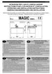
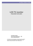
Pag. 1 di 4
ISTRUZIONI PER L'USO E L’INSTALLAZIONE
INSTRUCTIONS POUR L'UTILISATION ET L’INSTALLATION
OPERATING AND INSTALLATION INSTRUCTIONS
GEBRAUCHSANWEISUNGEN UND INSTALLATION
Elettroriduttore reversibile per cancelli a battente - Motoréducteur reversible pour portails à battant
Reversible actuator for leaf gates - Nicht-Selbsthemmender Torantrieb für Flugeltore
mod.
I
PRATIC
IMPORTANTI ISTRUZIONI PER LA SICUREZZA
GB
IMPORTANT SAFETY INSTRUCTIONS
ATTENZIONE - É IMPORTANTE PER LA SICUREZZA DELLE PERSONE
CHE VENGANO SEGUITE TUTTE LE ISTRUZIONI
CONSERVARE CON CURA QUESTE ISTRUZIONI
1° - Tenete i comandi dell'automatismo (pulsantiera, telecomando etc.) fuori dalla portata dei
bambini. I comandi devono essere posti ad un’altezza minima di 1,5mt dal suolo e fuori dal
raggio d’azione delle parti mobili.
2° - Effettuare le operazioni di comando da punti ove l'automazione sia visibile.
3° - Utilizzare i telecomandi solo in vista dell'automazione.
4° - Prima di eseguire qualsiasi operazione di installazione, regolazione, manutenzione
dell’impianto, togliere la tensione agendo sull’apposito interruttore magnetotermico collegato a
monte dello stesso.
5° - Avvertenze: Sulle altre misure di Protezione contro rischi attinenti l'installazione o l'utilizzazione
del Prodotto vedi, a completamento di questo libretto di Istruzioni, le Avvertenze RIB allegate.
Qualora queste non siano pervenute chiederne l'immediato invio all'Ufficio Commerciale RIB.
LA DITTA RIB NON ACCETTA NESSUNA RESPONSABILITÀ per eventuali danni provocati dalla
mancata osservanza nell'installazione delle norme di sicurezza e le leggi attualmente in vigore.
WARNING - IT IS IMPORTANT FOR THE
SAFETY OF PERSONS TO FOLLOW ALL INSTRUCTIONS
SAVE THESE INSTRUCTIONS
1° - Keep the automatic control (push-button, remote control, etc) out of the reach of children. The
control systems must be installed at a minimum hight of 1.5m from the ground surface and not
interfere with the mobile parts.
2° - Command pulses must be given from sites, where you can see the gate.
3° - Use transmitters only if you can see the gate.
4° - Before starting any installation and operation or maintenance work make sure to cut off power
supply by turning the general magnetothermic switch off.
5° - Warnings: when you have finished reading this instruction booklet, please refer to the RIB
instructions attached for the other precautionary measures against risks connected with the
installation or use of the product. If you have not received these, ask RIB Export Office to send
them immediately.
R.I.B. IS NOT LIABLE for any damage caused by not following the safety regulations and laws at
present in force not being observed during installation.
ATTENZIONE - UNA SCORRETTA INSTALLAZIONE PUÓ PORTARE A DANNI RILEVANTI
SEGUIRE TUTTE LE ISTRUZIONI PER UNA CORRETTA INSTALLAZIONE
1° - Questo libretto d'istruzioni è rivolto esclusivamente a del personale specializzato che sia
a conoscenza dei criteri costruttivi e dei dispositivi di protezione contro gli infortuni per i
cancelli, le porte e i portoni motorizzati (attenersi alle norme e alle leggi vigenti).
2° - Se non é previsto nella centralina elettrica, installare a monte della medesima un'interruttore di
tipo magnetotermico (onnipolare con apertura minima dei contatti pari a 3mm) che riporti un
marchio di conformità alle normative internazionali.
3° - Per la sezione ed il tipo dei cavi la RIB consiglia di utilizzare un cavo di tipo NPI07VVF con
sezione minima di 1,5mm2 e comunque di attenersi alla norma IEC 364 e alle norme di
installazione vigenti nel proprio Paese.
WARNING -INCORRECT INSTALLATION CAN LEAD TO SEVERE INJURY
FOLLOW ALL INSTALLATION INSTRUCTIONS
1° - This instruction booklet is exclusively dedicated to specialized staff who are aware of the
construction criteria and of the accident prevention protection devices for motorized gates and
doors (according to the current regulations and laws).
2° - To maintain electrical parts safely it is advisable to equip the installation with a differential
thermal magnetic switch (onnipolar with a minimum opening of the contacts of 3mm) and must
comply with the international rules.
3° - As for electric cable type and section RIB suggests cable type <HAR> with minimum section of
1,5mm2 and however respect IEC 364 rule and general national security regulations.
F
INSTRUCTIONS IMPORTANTES POUR LA SECURITE
IL EST IMPORTANT POUR LA SECURITE DES PERSONNES DE SUIVRE
ATTENTIVEMENT TOUTES INSTRUCTIONS GARDER MODE D’EMPLOI
1° - Gardez les commandes de l'automatisme (boutons poussoirs, télécommande etc.) hors de la
portée des enfants. Les commandes doivent être placées au minimum à 1,5 m du sol, et hors
de rayon d’action des pièces mobiles.
2° - Il faut donner les commandes d'un lieu, où on peut voir la porte.
3° - Il faut utiliser les émetteurs seulement si on voit la porte.
4° - Avant d’exécuter quelconques opérationd’installation, réglage, entrietien de l’installation,
couper la tension avec l’interrupteur magnétothermique approprié connecté en amont.
5° - Avertissements: Sur les autres mesures de Protection contre les risques relatifs a l'installation
ou l'utilisation du Produit, voir, à titre de complément de ce livret d'instructions, les
Avertissements RIB ci-jointes. Dans le cas où celles-ci ne vous seraient pas parvenues, en
demander l'envoi immédiat au Bureau d’Exportation de RIB.
L'ENTREPRISE R.I.B. N'ACCEPTE AUCUNE RESPONSABILITÉ pour des dommages éventuels
provoqués par le manque d'observation lors de l'installation des normes de sécurité et lois
actuellement en vigueur.
ATTENTION - UNE INSTALLATION INCORRECTE PEUT CAUSER DE GRANDS DOMMAGES
SUIVRE TOUTES INSTRUCTIONS POUR UNE CORRECTE INSTALLATION
1° - Ce manuel d'instruction est adressé seulement au personnel specialisé qui a une
connaissance des critères de construction et des dispositifs de protection contre les accidents
en ce qui concerne les portails, les portes et les portes cochères motorisées (suivre les normes
et les lois en vigueur).
2° - A fin de procéder à l'entretien des parties électriques, connecter à l'installation un disjoncteur
differentiel magneto thermique (qui disconnait toutes les branchements de la ligne avec
ouverture min. des branchements de 3 mm ) et qui soit conforme aux normes internationales.
3° - Pour la section et le type des câbles à installer nous vous conseillons d’utiliser un cable <HAR>
avec une section min de 1,5 mm2 en respectant quand même la norme IEC 364 et les normes
nationales d'installation.
D
WICHTIGE ANWEISUNGEN FÜR DIE SICHERHEIT
ACHTUNG - UM DIE SICHERHEIT VON PERSONEN VOLLKOMMEN
GARANTIEREN ZU KöNNEN, IST ES WICHTIG, DASS ALLE
INSTALLATIONSVORSCHRIFTEN BEACHTET WERDEN
1° - Bewahren Sie die Geräte für die automatische Bedienung (Drucktaster, Funksender, u.s.w.) an
einem für Kinder unzugänglichen Platz auf. Die Steuerungen müssen auf einer Mindesthöhe
von 1,5 m angebracht werden und sich ausserhalb der Raumes der bewegenden Teile
befinden.
2° - Die automatische Steuerung darf nur bedient werden, wenn das Tor sichtbar ist.
3° - Die Funksender nur benützen, wenn das Tor sichtbar ist.
4° - Bevor Sie eine Installation oder Wartungsarbeit an der Anlage durchführen, müssen Sie
kontrollieren, dass die Anlage spannungsfrei geschaltet ist.
5° - Achtung: Für weitere Schutzmaßnahmen im Rahmen der Installation und Anwendung der
Produkte siehe die beiliegenden RlB-Sicherheitshinweise, die diese Gebrauchsanleitung
ergänzen. Sollten Sie diese nicht erhalten haben, fordern Sie sie bitte sofort bei der RlB
Exportabteilung an.
R.I.B. HAFTET NICHT für eventuelle Schäden, die bei der Installation durch Nichtbeachtung der
jeweils gültigen Sicherheitsvorschriften entstehen.
ACHTUNG - EINE FALSCHE INSTALLATION KANN ZU BEDEUTENDE SHADEN FÜHREN.
FÜR EINE KORREKTE ANLAGE ALLE ANWEISUNGEN BEFOLGEN
1° - Diese Montageanweisung ist ausschließlich für geschultes Fachpersonal bestimmt, das
mit den Montagevorschriften und den Schutzvorrichtungen zur Verhinderung von Unfällen bei
motorisierten Toren vertraut ist (nach den aktuellen Normen und Gesetzen).
2° - Für die Wartung der elektrischen Teile ist es ratsam, zwischen der Anlage und dem
Netzanschluß einen magnetisch-thermischen Differenzialschalter (mit Mindestöffnung aller
Kontakte von 3 mm) zu montieren, der alle internationalen Normen entspricht.
3° - Für den Kabelquerschnitt und die Kabeltypen halten Sie sich an den Normen IEC 364
(Mindest- Kabelquerschnitt von 1,5 mm2 mit der Bezeichnung <HAR>) und für die Montage an
die Normen des jeweiligen Landes.
Pag. 2 di 4
I
CARATTERISTICHE TECNICHE MOTORIDUTTORE
F
CARACTERISTIQUES TECHNIQUES MOTOREDUCTEUR
PRATIC è stato ideato per movimentare quei cancelli e quei portoni,
antichi o moderni, dotati di colonne di grandi dimensioni, che hanno le cerniere a una
notevole distanza dal filo interno della colonna.
PRATIC è un'attuatore elettromeccanico reversibile dotato di frizione in bronzo e
ingranaggeria meccaniche a bagno d'olio per garantire una maggior sicurezza dell'utente
e una buona resistenza meccanica dell'attuatore ai contraccolpi.
É dotato di leve per la movimentazione dell’anta e di 1,5mt di cavo elettrico già collegato
al motore per il collegamento alla centrale di comando.
Viene fornito con un contenitore in acciaio zincato di ridotte dimensioni (45,5x12,5
h12,5cm).
In caso di manutenzione il motore può essere rimosso senza toccare l'anta.
PRATIC è reversibile per facilitare la manovra manuale dell’anta e perciò non ha
bisogno di uno sblocco sul motore .
PRATIC può azionare agevolmente cancelli e portoni pesanti fino a 350Kg e con ante
lunghe fino a 2,5mt con un tempo medio di apertura di 20 secondi (nel rispetto delle
norme). PRATIC permette l'apertura dell'anta fino a 105°.
Per delimitare la corsa dell’anta è necessario montare sulla colonna (non a terra) dei
fermi meccanici (tamponi) alla stessa altezza del motore.
PRATIC è predisposto per l’applicazione di finecorsa elettrici (a richiesta) indispensabili
per un utilizzo intensivo dell’attuatore.
Essendo il PRATIC reversibile si consiglia di dotare le ante di una elettroserratura per
mantenere un’efficace posizione di chiusura.
PRATIC a été conçu pour l’actionnement de portails et de portes, neufs
ou deja existants, montés sur des piliers de grandes dimensions avec des charnières
éloignées du bord interieur du poteau.
PRATIC est un actionneur électromecanique réversible, équipé d’un embrayage en
bronze et d’engrenages mécaniques en bain d’huile pour garantir une meilleure sécurité
à l’utilisateur et une bonne résistance mécanique aux chocs.
Il est équipé de leviers pour l’actionnement du vantail et d’un câble électrique de 1,5
mètres déjà raccordé au moteur pour la connexion de la centrale de commande.
Il est contenu dans un coffret en acier galvanisé de petites dimensions (45,5 x 12,5H x
12,5 cm).
Si nécessaire, le moteur peut être retiré sans toucher le vantail.
PRATIC est réversible pour faciliter la manoeuvre manuelle du vantail et n’a donc pas
besoin d’un dispositif de déverrouillage sur le moteur.
PRATIC peut actionner sans forcer des portails et des portes pesant jusqu’à 350 kg,
avec des ventaux mesurant jusqu’à 2,5 mètres et un temps moyen d’ouverture de 20
secondes (conformément aux normes).
PRATIC permet l’ouverture du vantail jusqu’à 105°.
Pour délimiter la course du vantail, il est nécessaire de monter des butées mécaniques
(tampons) sur le pilier (jamais au sol) à la même hauteur que le moteur.
PRATIC est prévu pour l’application de fins de courses électriques (en option), qui sont
indispensables en cas d’utilisation intensive de l’actionneur.
PRATIC étant réversible, il est conseillé de monter une serrure électromécanique sur le
portail pour un bon verrouillage en fermeture.
GEARMOTOR TECHNICAL CHARACTERISTICS
The PRATIC is designed for those gates and doors, antique and modern
alike, which are hung from massive columns on hinges centred at an appreciable
distance from the inside face of the column.
The PRATIC is a reversible electromechanical actuator equipped with oil-immersed
gears and a bronze clutch guaranteeing increased user safety and superior mechanical
strength of the actuator in withstanding recoil.
The equipment includes transmission levers for connection to the leaf, and a motor with
1.5 metres of prewired cable requiring connection only to the control unit.
Also supplied is a galvanized steel housing of compact dimensions (45.5 x 12.5 x h12.5
cm).
The motor can be removed for servicing without disturbing the door or gate.
Being reversible, the PRATIC allows any door or gate leaf to swing easily when pushed
by hand, and there is no motor release mechanism required.
The PRATIC is comfortably able to operate gates and doors weighing up to 350 kg with
leaves up to 2.5 metres in length, in an average time of 20 seconds (complies with
current standards). The PRATIC has an operating arc of 105°.
To limit the travel of the gate or door leaf, mechanical stops (buffers) must be mounted to
the column (not at floor level) in alignment with the motor.
The PRATIC is designed to operate in conjunction with electric limit switches (optional),
which in practice are essential for applications characterized by intensive use.
Given that the PRATIC is a reversible drive, it is recommended that leaves be fitted with
an electric lock to ensure stability in the closed position.
GB
TECHNISCHE DATEN GETRIEBEMOTOR
D
Der Antrieb “PRATIC” wurde hergestellt um sowohl bestehende als auch
neugebaute Flügeltore automatisieren zu können, derer Torscharnier einen
beträchtlichen Abstand zur inneren Torsäule hat.
PRATIC ist ein nicht selbsthemmender Flügeltorantrieb deren Rutschkupplung aus
Bronze und sämtliche Zähnräder im Ölbad eine erhobene Sicherheitsstufe zu den
Endverbrauchern garantieren können. Der Antrieb ist mit zwei Toranschlusshebel
versehen und zusammen mit 1,5Mt schon am Motor angeschlossenen E-Kabel geliefert
wird.
Das Antriebsgehäuse ist aus verzinkten Stahl.
Die Maßen des Antriebes sind 45,5x12,5x12,5 cm.
Der Antrieb ist wartungsfrei.
PRATIC ist ein nicht selbsthemmender Antrieb.
Eine Handbetätigung des Tores ist ganz einfach.
Notentriegelung ist nicht vorhanden. Der Antrieb “PRATIC” kann die Flügeltore bis zu
350Kg netto-Gewicht und eine Flügellänge bis zu 2,5Mt mit einem durchschnittlichen
Öffnungsgeschwindigkeit von 20 sec in Bewegung setzen.
Die Tore die mit PRATIC automatisiert werden, können einen Öffnungswinkel bis zu
105° haben.
Um den Torflügellauf begrenzen zu können, ist erforderlich mechanische Anschläge
einbauen lassen.
Eine Ausführung mit Endschaltern ist aber in einem weiteren Schritt vorgesehen.
PRATIC ist für elektrische Endschalter gedacht (die müssen aber bestellt werden), die
für intensive Benützung notwending sind.
Da der “PRATIC” ein nicht selbsthemmender Antrieb ist ein Elektroschloß ist auf jedem
Fall zu installieren um eine wirksame Schließung des Tores zu gewähren.
CARATTERISTICHE
TECNICHE
CARACTERISTIQUES
TECHNIQUES
TECHNICAL
DATA
TECHNISCHE
EIGENSCHAFTEN
Lunghezza max.anta
Longueur maximale vantail
Max. leaf length
Max. Torflügelweite
m.
2,5
Peso max cancello
Poids maximal vantail
Max. leaf weight
Max. Torgewicht
kg
350
Tempo medio di apertura
Temps moyen d’ouverture
Average opening time
Mittlere Öffnungszeit zirka
s
20
Coppia massima
Couple maximal
Thrust force
Max Drehmoment
Nm
200
Alimentazione e frequenza CEE
Alimentation et fréquence CEE
EEC Power supply
Stromspannung und frequenz CEE
Potenza motore
Puissance moteur
Motor capacity
Motorleistung
W
190
Assorbimento
Consommation
Power absorbed
Stromaufnahme
A
0,85
Condensatore
Condensateur
Capacitor
Kondensator
µF
6,3
n° di cicli
Nbre. de cycles
No. cycles
Zycluszahl
n°
Lubrificazione a olio
Lubrification par huile
Lubrification
Ölsorte
Peso max
Poids maximal
Weight of electroreducer
Motorgewicht
Kg
12
Rumorosità
Niveau sonore
Noise
Geräusch
db
<70
Volume
Volume
Volume
Volumen
m3
0,0071
Grado di protezione
Degré de protection
Protection
Schutzart
IP
677
PRATIC
230V ~ 50Hz
40 - 20s/2s
Bechem Staroel NR100
Pag. 3 di 4
390
650
Applicazione con leva di traino a slitta
Version avec levier de traction coulissant
Application with slide transmission lever
Anwendung mit hebel in rollbahn
50
min 130
110 max 310
asse
cerniera
min 140
max 240
asse
riduttore
700
70
Lungh. anta
Leaf length
Long. du battant Torflügelweite
0 ÷ 1,5
1,5 ÷ 2
2 ÷ 2,5
A
B
C
D
0÷100
450
700
–
350
500
–
400
530
–
0 ÷ 1,5
1,5 ÷ 2
2 ÷ 2,5
100÷200
530
490
750
350
500
500
390
580
540
0 ÷ 1,5
1,5 ÷ 2
2 ÷ 2,5
200÷300
600
530
780
350
500
500
360
570
560
0 ÷ 1,5
1,5 ÷ 2
2 ÷ 2,5
300÷400
600
600
680
500
500
500
560
560
580
0 ÷ 1,5
1,5 ÷ 2
2 ÷ 2,5
400÷500
680
680
500
500
550
550
Filo inferiore supporto riduttore
I
80
Applicazione con leve di traino normali
Version avec leviers de traction normaux
application with standard transmission levers
Normale anwendung mit hebel
REGOLAZIONE FRIZIONE DI SICUREZZA
N.B.: Queste operazioni devono essere eseguite dopo avere tolto
l'alimentazione elettrica del motore.
1 ) Allentare il dado (1) con chiave fissa n° 17.
2) Trattenere l'albero motore con chiave fissa n° 13 e avvitare il grano (2) con chiave a
brugola n° 6 in senso orario se si vuole dare maggior potenza di spinta, antiorario se
serve meno spinta.
3) A regolazione avvenuta ricordarsi di ribloccare il dado (1) contro l'estremità dell'albero.
4) Far scorrere il cancello elettricamente più volte trattenendolo con le mani, in modo che
la forza di spinta sia leggermente superiore a quella richiesta per movimentare il
cancello.
5) A regolazione avvenuta ricordarsi di bloccare il dado contro l'albero motore.
ATTENZIONE: Più si avvita la vite (2), più forza il motore
trasmette al cancello, più resistenza offre il motore ad
eseguire la manovra manuale in mancanza di corrente.
Non forzare il movimento del cancello agendo sulla
2
regolazione della frizione più del necessario!
F
REGLAGE EMBRAYAGE DE
SECURITE
Ces operations doivent être executées aprés avoir coupé
I'alimentation.
1) Dévisser l'écrou (1) à l'aide d'une clef plate de 17 mm.
2) Maintenir l'arbre moteur à l'aide d'une clef plate de 13 mm et serrer la vis (2) pour
donner plus de couple. Désserer pour le diminuer.
3) Après obtention du réglage voulu, bien bloquer le contre-écrou (1) sur l'arbre moteur.
4) Faire coulisser le portail électriquement à plusieurs reprises en retenant celui-ci avec
les mains, de manière que la force de poussée soit légèrement supérieure à celle
requise pour mettre le portail en mouvement.
5) Le réglage effectué, se rappeler de bloquer l'écrou contre l'arbre moteur.
ATTENTION : Plus on serre la vis (2), plus le moteur transmet de force au portail,
plus le moteur offre de résistance à l'exécution de la manœuvre manuelle en
l'absence de courant. Ne pas forcer le mouvement du portail en intervenant plus
que nécessaire sur le réglage de l'embrayage !
GB
ADJUSTMENT OF THE SAFETY CLUTCH
N.B.: These operations must be executed only after the power supply
has been suspended.
1) Unscrew the unit with a 17 mm wrench (1).
2) Hold the motor with a 13 mm wrench and turn the screw (2) clockwise (with the given
wrench) if you want more force or unscrew it if you need less.
3) After regulating the clutch do not forget to clamp the nut (1) at the shaft's end.
4) Let the gate move electrically a number of times, holding it with your hands so that the
thrust force is slightly higher than that actually required to move the gate.
5) When adjustment has been completed, remember to fasten the nut at the motor shaft.
WARNING: The more the screw (2) is tightened, the more force the motor transmits
to the gate and the more it will offer resistance to manual movement during a
power failure. Do not force gate movement by
adjusting the friction more than necessary!
1
D
EINSTELLUNG DER
SICHERHEITSKUPPLUNG
N.B.: Diese Operationen sind nur ausführbar nachdem
der Antrieb aus dem Netz ausgeschaltet worden ist.
1) Die Mutterschraube (1) ist mit dem 17 mm
Maulschluessel zu lockern.
2) Die Antriebswelle ist mit einem 13 mm Maulschluessel festzuhalten und gleichzeitig die
Schraube (2) mit dem dazugehöerenden Schlüssel im Uhrzeigerssinn anzuziehen,
wenn Sie dem Antrieb mehr Schubleistung geben moechten, dagegen, wenn Sie
weniger Schubleistung brauchen, ist die Schraube gegen den Uhrzeigsinn zu lockern.
3) Nach der Einstellung der Rutschkupplung ist die Schraubenmutter (1) wieder gegen
Antriebswelle festzuschrauben.
4) Lassen Sie das Tor nun einige Male hin- und hergleiten Halten Sie es mit den Händem
zurück, um die Druckkraft leicht über der für die Torbewegung notwendige zu liegen.
5) Nach erfolgter Einstellung ist die Schraubenmutter wieder gegen die Motorwelle
anzuziehen.
Achtung! Je stärker die Schraube (2) angezogen wird, desto größer ist die vom
Motor auf das Tor übertragene Kraft und desto höher ist auch der Widerstand des
Motors bei manueller Betätigung im Fall des Stromausfalls. Die Bewegung des Tors
nicht übermäßig durch Verstellen der Kupplung forcieren!
Pag. 4 di 4
BLUE
BLACK
BROWN
- Common to be connected to clamp U
- Inverter to be connected to clamp V
- Inverter to be connected to clamp W
BLAU
SCHWARZ
BRAUN
- Verbindung dass zu Klemme U (Kollegiert werden muß)
- Wender dass zu Klemme V (Kollegiert werden muß)
- Wender dass zu Klemme W (Kollegiert werden muß)
N.B.: IL CONDENSATORE VA COLLEGATO TRA I FILI MARRONE E NERO
THE CAPACITOR MUST BE CONNECTED BETWEEN THE BROWN AND THE BLACK WIRES
DER KONDENSATOR MUß ZWISCHEN BRAUNEN UND SCHWARZEN DRAHT VERBINDET WERDEN
BA00170
BA01012
BA01014
CAL1060
CAL1084
CCA1550
CCA1551
CCM6301
CCU6005
CEL1379
CEL1384
CEL1810
CME6032
CME6077
Denominazione Particolare
Statore 230V~ 50Hz
Statore 220V~ 60Hz
Statore 110V~ 60Hz
Corona Z=39
Corona Z=28
Supporto riduttore
Carter copri finecorsa
Cuscinetto motore 63012RS
Cuscinetto 6005 (25X47X12)
Condensatore 25µF 450V
Condensatore 6,3µF 450V
Pressacavo PRA 14/9 G1/4 IP67
2° pignone
1° pignone
Codice
CME8002
CME8003
CME9826
CME9870
CME9871
CME9875
CME9876
CME9877
CMO1310
CPL1205
CTC1008
CTC1013
CTC1035
CTC1092
Denominazione Particolare
Puntale per frizione
Disco frizione
Corona elicoidale
Albero traino
Flangia albero traino
Semi carcassina destra
Semi carcassina sinistra
Flangia anteriore
Rotore con albero
Carter
Chiavetta 6 6 30
Chiavetta 8 7 25
Serie guarnizioni
Paraolio 14x22x4
Codice
CTC1094
CTC1117
CTC1123
CTC1227
CTC1310
CTC1404
CVA1146
CVA1320
CZM6203
CZZ6202ZZ
DDBM10I
DRL173003
DST10X20I
Denominazione Particolare
Paraolio 17x28x7
Seeger E15
Seeger E25
Molla a tazza 16,3x31,5x1,25
Anello di tenuta OR2018
Paraolio 25x40x8
Tappo Jacob
Puntale
Cuscinetto motore 6203ZZ
Cuscinetto 6202ZZ
Dado M10 basso inox
Rondella 17x30x0,3
Grano M10X20
La ditta RIB si riserva il diritto di modificare le caratteristiche tecniche, i colori, ecc. in qualunque momento senza preavviso
La société RIB se réserve le droit de modifier à tout moment les caractéristiques techniques, la couleur, etc. de ses produits sans pour autant devoir en donner préavis.
The right is reserved by RIB to alter technical specifications, colours etc. at any time without prior notice.
RIB behält sich den Recht die technische Eigenschaften,Färben usur in jeden Moment und ohne vorherige Benachrichtigung zu verändern.
®
25014 CASTENEDOLO (BS) - ITALY
Via Matteotti, 162
Telefono ++39.030.2135811
Fax ++39.030.21358279-21358278
automatismi per cancelli
http://www.ribind.it
- email: [email protected]
automatic entry systems
La presente macchina non può funzionare in modo
indipendente ed è destinata ad essere incorporata in
un impianto costituito da ulteriori elementi. Rientra
perciò nell’Art. 4 paragrafo 2 della Direttiva
89/392/CEE (Macchine) e successive modifiche, per
cui segnaliamo il divieto di messa in servizio prima che
l’impianto sia stato dichiarato conforme alle
disposizioni della Direttiva
Il Presidente
Cod. AA18001 - 011007 - Rev.07
Codice