1
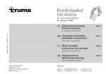
Multivent TBM
Gebrauchsanweisung
Einbauanweisung
Seite 2
Seite 4
Im Fahrzeug mitzuführen!
Operating instructions
Installation instructions
Page 5
Page 6
To be kept in the vehicle!
Mode d‘emploi
Instructions de montage
Page 7
Page 8
À garder dans le véhicule !
Bruksanvisning
Monteringsanvisning
Skall medföras i fordonet!
Sita 9
Sita 10
A
C
1
124 mm
m
3
2
2
Ø
55
m
8
4
3
7
0
13
m
m
9
6
11
12 V
B
D
E
12 V
2
5
10
11
Truma Multivent – Zweistufiges 12 V Universalgebläse
Gebrauchsanweisung
Technische Daten
(ermittelt nach EN 624 bzw. Truma Prüfbedingungen)
Kurzbeschreibung
Das Gebläse Truma Multivent TBM eignet sich für die Warmluftverteilung an der Heizung Trumatic S 2200 (Bild A), als
Dunstabzug oder Ventilator in der Küche oder im Schlafraum
(Bild B) oder zur Steigerung der Luftleistung in bestehenden
Warmluftanlagen mit besonders langen Rohrleitungen.
Multivent
b
a
Betriebsspannung
12 V Gleichspannung
Stromaufnahme
bei Halbstellung 0,23 A
bei Vollstellung 0,5 A
Luftfördermenge
bei Halbstellung 29 m³/h
bei Vollstellung 60 m³/h
EG-Typgenehmigung
e1 03 2603
c
a = Aus
b = Halbstellung
c = Vollstellung
Inbetriebnahme
Am Bedienteil auf die gewünschte Leistung (b oder c)
einschalten.
Ausschalten
Am Bedienteil ausschalten (a).
3
Einbauanweisung
Einbau und Reparatur des Truma Multivent darf nur vom
Fachmann durchgeführt werden.
Bei Verwendung von fahrzeug- bzw. herstellerspezifischen
Bedienteilen muss der elektrische Anschluss gemäß
den Truma Schnittstellenbeschreibungen erfolgen.
Für den Anschluss am Einbaukasten EKM oder der Rückwand mit Wärmeleitblech mittels Lüfterrohr ÜR Ø 65 mm
ist eine Ansaugdüse DM (Bild D: Art.-Nr. 40670-00) erforderlich.
1. Bild C
Gebläse (1) mit 2 Schrauben (2) an Boden, Wand, Decke usw.
befestigen (Gebläse funktioniert in jeder Lage).
2. Lüfterrohre Ø 65 mm (ÜR) in die Rohrstutzen einschieben
und mit Blechschrauben (3) sichern.
3. Platz für das Bedienteil (5) an gut sichtbarer Stelle vorsehen.
Ist eine Unterputzmontage nicht möglich, liefert Truma
auf Wunsch einen Aufputzrahmen (7 – Art.-Nr. 4000052600) als Zubehör.
4. Kabel (4) vom Gebläse (1) zum vorgesehenen Platz für das
Bedienteil (5) verlegen. Falls erforderlich, mit einem Kabel
3 x 0,75 mm² verlängern.
5. Loch Ø 55 mm bohren. Anschlusskabel vom Gebläse (4)
und Zuleitung 12 V (9) von hinten durch die Bohrung in der
Wand führen und gemäß Anschlussschema (Bild E) am
Bedienteil anklemmen.
1 = weiß
2 = braun
3 = grün
– = Zuleitung Minus
+ = Zuleitung Plus 12 V
Bild C
Hintere Abdeckkappe (8) als Zugentlastung aufsetzen und
Bedienteil (5) mit 4 Schrauben (10) befestigen. Anschließend
Abdeckrahmen (6) aufstecken.
Zum optischem Abschluss der Abdeckrahmen (6) liefert
Truma Seitenteile (11) in 8 verschiedenen Farben. Bitte
fragen Sie Ihren Händler.
Gerät am abgesicherten Bordnetz (Zentralelektrik 5 – 10 A) mit
Kabel 2 x 0,75 mm² anschließen. Bei direktem Anschluss an
die Batterie ist die Plus- und Minusleitung abzusichern.
Alle Kabel mit Kabelschellen sichern.
Bei Verwendung von Netzteilen ist zu beachten, dass die
Ausgangsspannung zwischen 11 V und 15 V liegt und
die Wechselspannungswelligkeit < 1,2 Vss beträgt.
Funktionsprüfung
Nach dem Einbau sämtliche Funktionen gemäß der Gebrauchsanweisung prüfen.
Die Gebrauchsanweisung ist dem Betreiber auszuhändigen!
4
Truma Multivent – Two-stage 12 V universal fan
Operating instructions
Technical data
(determined in accordance with EN 624 or Truma test
conditions)
Short Description
The Truma fan Multivent TBM is designed for the air distribution on the heater Trumatic S 2200 (fig. A), as a vapour
escape or as a ventilator in the kitchen or in the bathroom
(fig. B) or to increase the air output in existing warm air
distribution systems with extremly long ducting.
Multivent
b
a
Operational voltage
DC voltage 12 V
Current consumption
0.23 A in position 1/2
0.5 A in position 1
Air output
29 m³/h in position 1/2
60 m³/h in position 1
EC Type Approval
e1 03 2603
c
a = off
b = position 1/2
c = position 1
Operation
Switch to the desired power level (b or c) on the control panel.
Switching off
Switch off at the control panel (a).
5
Installation instructions
Installation and repair of the Truma Multivent fan may
only carried out by an expert.
When using control panels which are specific to the
vehicle or manufacturer, the electrical connection
must be effected in accordance with Truma interface
specifications.
For connection of the fan with air duct ÜR 65 mm dia.
to the installation box EKM or the rear panel with heat
deflector, a intake nozzle DM (fig. D: part no. 40670-00) is
required.
1. fig. C
Fix the fan (1) with two screws (2) to the floor, to the wall, to
the ceiling etc. (the fan works in all positions).
2. Push the ducts ÜR 65 mm dia. for the warm air distribution into the connection fittings and fasten with self tapping
screws (3).
3. Choose a place for the control panel (5) in a position which
is easy to view.
If flush mounting is not possible, Truma will supply an
on-surface frame (7 – part no. 40000-52600) as an
accessory on request.
4. Lay the cable (4) from the fan (1) to the place intended for
the operating unit (5). If required, use a cable 3 x 0.75 mm² as
an extension.
5. Drill a 55 mm diameter hole. Feed the connection cable
from the fan (4) and 12 V lead (9) from behind through the
hole in the wall, and connect it to the operating unit in accordance with the connection diagram (fig. E).
1 = white
2 = brown
3 = green
– = negative lead
+ = positive lead 12 V
Fig. C
Fit the rear cover cap (8) as a stress-relieving device, then secure the control panel (5) with 4 screws (10) and fit the cover
frame (6).
Truma offers side parts (11) in eight different colors for
finishing the cover frames (6) in a visually pleasing way.
Please ask your dealer.
Connect fan to fused vehicle power supply (central electrical
system 5 – 10 A) using a cable 2 x 0.75 mm². When connecting directly to the battery, always fuse the positive and negative lead.
Secure all cables with cable clips.
When power supplies are being used, it must be noted
that the output voltage is between 11 V and 15 V and the
alternating current ripple is < 1.2 Vss.
Function test
After installation, check all the functions in accordance with
the Operating Instructions.
The operating instructions must be handed over to the user!
6
Truma Multivent – Soufflerie universelle 12 V à deux niveaux
Description courte
Caractéristiques techniques
Le ventilateur Truma Multivent TBM convient à la distribution
de l’air chaud du chauffage Trumatic S 2200 (fig. A). Il est
aussi utilisé comme hotte d’évacuation des buées ou pour la
ventilation dans la cuisine ou le dortoir (fig. B) ainsi que pour
l’augmentation du débit d’air dans des installations de distribution d’air chaud avec des tuyaux d’une grande longueur.
Multivent
b
a
c
(établies selon la norme EN 624 et les conditions de contrôle
Truma)
Tension de service
Courant continu 12 V
Consommation de courant
0,23 A en pos. 1/2,
0,5 A en pos. 1
Débit d’air
29 m³/h en pos. 1/2,
60 m³/h en pos. 1
Homologation CE
e1 03 2603
a = arrêt
b = pos. 1/2
c = pos. 1
Mise en service
Au niveau de la pièce de commande, mettre en marche sur la
puissance souhaitée (b ou c).
Arrêt
Arrêt sur la pièce de commande (b).
7
Instructions de montage
La mise en place et la réparation du Multivent de Truma
ne doivent être effectuées que par un spécialiste.
5. Percer un trou de Ø 55 mm. Passer le câble de raccordement
de la soufflerie (4) et le câble d’alimentation 12 V (9) dans le
mur, par l’arrière, à travers le trou de perçage et les connecter
à la pièce de commande conformément au schéma de
raccordement (fig. E).
Lors de l’utilisation d’éléments de commande spécifiques
de véhicules ou de constructeurs, la connexion électrique
doit être réalisée en conformité avec les descriptions
d’interfaces Truma.
1 = blanc
2 = marron
3 = vert
– = Câble d’amenée du moins
+ = Câble d’amenée du plus 12 V DC
Pour monter le ventilateur par les conduites d’air chaud
Ø 65 mm (ÜR) à la niche EKM ou le panneau arrière avec
déflecteur de chaleur, une tuyère d’aspiration DM (fig. D :
n° d’art. 40670-00) est indispensable.
Fig. C
Installer le capuchon de protection arrière (8) qui servira de
décharge de traction, puis fixer la pièce de commande (5) à
l’aide de 4 vis (10). Pour finir, poser le cadre de protection (6).
1. Fig. C
Fixer le ventilateur (1) au sol, au mur, au plafond etc. par
deux vis (2). (Le ventilateur fonctionne dans n’importe quelle
position).
Pour la finition du cadre de protection (6), Truma fournit
des pièces latérales (11) dans 8 coloris différents. Veuillez
demander à votre concessionnaire.
2. Insérer les conduites d’air chaud de Ø 65 mm (ÜR) dans les
tubulures du ventilateur et fixer-les par des vis à tôle (3).
Brancher l'appareil, protégé par un fusible (système électrique
central 5 à 10 A), au réseau de bord avec un câble de
2 x 0,75 mm². En cas de branchement direct à la batterie,
protéger les fils plus et moins.
3. Prévoir une place bien visible pour la pièce de commande (5).
Fixer tous les câbles avec des colliers.
Si un montage encastré n‘est pas possible, Truma fournit
sur demande un cadre en applique (7 – n° d‘art. 4000052600) en tant qu‘accessoire.
4. Poser le câble (4) depuis la soufflerie (1) jusqu’à l’emplacement prévu pour la pièce de commande (5). Si nécessaire, le
rallonger avec un câble de 3 x 0,75 mm².
En cas d'utilisation de blocs d'alimentation secteur,
veiller à ce que la tension de sortie soit située entre 11 V
et 15 V et l'ondulation de tension alternative < 1,2 Vss.
Contrôle de fonctionnement
Après avoir mis en place l’appareil, contrôler l’ensemble de
ses fonctionnalités en se conformant au mode d’emploi.
Remettre le mode d’emploi à l’utilisateur!
8
Truma Multivent – Tvåstegs 12 V universalfläkt
Bruksanvisning
Tekniska data
(bestämda enligt EN 624 resp. Truma-provningsvillkor)
Kort beskrivning
Trumas fläkt, Multivent TBM är lämplig vid varmluftsfördelning
från mindre värmepannor som Trumatic S 2200 (bild A), som
köksfläkt eller ventilation i kök och sovrum (bild B) eller som
förstärkningsfläkt vid långa rördragningar.
Multivent
b
a
Driftsspänning
Likspänning 12 V
Strömförbrukning
Halvfart: 0,23 A
Helfart: 0,5 A
Luftkapacitet
Halvfart: 29 m³/h
Helfart: 60 m³/h
EG-typgodkännande
e1 03 2603
c
a = Av (Off)
b = Halvfart
c = Helfart
Igångkörning
Ställ in den önskade effekten (b eller c) på manöverdelen
Avstängning
Vredet vrides till läge (a) på manöverdelen.
9
Monteringsanvisning
Montage och reparationer på Truma Multivent får
endast utföras fackmän.
Vid användning av fordons- resp. tillverkarspecifika
manöverdelar, måste den elektriska anslutningen ske
enligt Trumas gränssnittsbeskrivningar.
För anslutning på inbyggnadskasett EKM eller bakvägg
med värmeledningsplåt med hjälp av luftslang ÜR Ø 65 mm,
erfordras insugnings-dosa DM, art.nr 40670-00 (bild D).
1. Bild C
Fäst fläkten (1) med hjälp av två skruvar (2) mot golv, vägg eller däck (Fläkten kan monteras på alla håll).
1 = Vit
2 = Brun
3 = Grön
– = Nätkabel minus
+ = Nätkabel plus 12 V
Bild C
Använd den bakre täckkåpan (8) som dragavlastare och skruva därefter fast panelen (5) med 4 skruvar (10). Fäst därefter
täckramen (6).
Som synlig avslutning till täckramarna (6) levererar Truma
sidodelar (11) i 8 olika färger. Fråga din representant.
Anslut apparaten till fordonets jordade elsystem (centralel
5 – 10 A) med kabel 2 x 0,75 mm². Vid direktanslutning till
batteriet ska plus- och minusledningen jordas.
Alla ledningar måste fästas med klammer.
2. Skjut in luftslang ÜR, Ø 65 mm i rörmuffen och säkra med
plåtskruvar (3).
3. Montera manöverpanelen (5) på väl synlig plats.
Om infälld montering inte är möjlig levererar Truma på
begäran en dosa för utanpåliggande montering (7 – art.
nr 40000-52600) som tillbehör.
4. Dra ledningen (4) från fläkten (1) till den förutsedda platsen
för manöverdelen (5). Förläng den om så erfordras med en
ledning 3 x 0,75 mm².
5. Borra ett hål Ø 55 mm. För in anslutningsledningen från
fläkten (4) och 12 V-matningen (9) bakifrån genom hålet i väggen och anslut dem till manöverdelen enligt kopplingsschemat (bild E).
10
När nätdelar används måste tillses att utgångsspänningen ligger mellan 11 V och 15 V och att växelspänningens
pulsation uppgår till < 1,2 VSS.
Funktionskontroll
Kontrollera efter montaget samtliga funktioner enligt
bruksanvisningen.
Bruksanvisningen skall överlämnas till användaren!
39030-23200 · 02 · 12/2010 · Om · ©
Truma Gerätetechnik
GmbH & Co. KG
Wernher-von-Braun-Straße 12
85640 Putzbrunn
Service
Telefon
Telefax
+49 (0)89 4617-2142
+49 (0)89 4617-2159
[email protected]
www.truma.com