1
Installation instructions
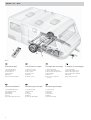
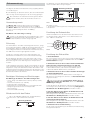
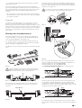
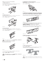
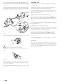
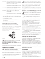
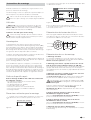
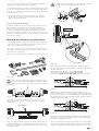
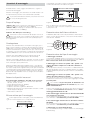
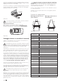
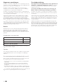
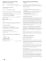
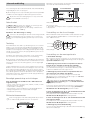
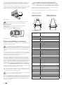
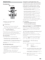
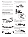
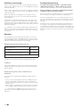
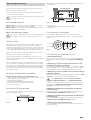
Installation is only possible on caravans / trailers with the following dimensions.
Read the installation instructions carefully before commencing the work, and then comply with them!
min. 25
min. 35 **
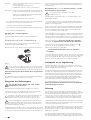
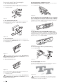
In the case of screws with sealant, make sure that the
thread is free of grease/oil.
min.
170*
140
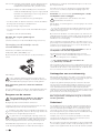
Please ensure that no metal chips or other contaminants get
into the control unit during installation.
min. 2.8
Caravan floor
min. 50
min. 1350 / max. 2000
max. 2400
Intended use
Fig. 7
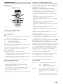
The Mover® XT was designed for use on single-axle
caravans with a gross weight of up to 2300 kg.
The Mover® XT2 was designed for use on dual-axle
caravans with a gross weight of up to 2400 kg.
All dimensions in mm.
* with loaded vehicle with max. permissible gross weight
** with U-profile
The Mover® XT / XT2 weighs approx. 28 kg.
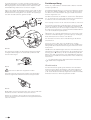
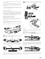
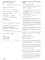
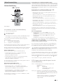
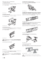
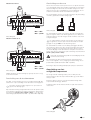
Measuring the frame height
Check the maximum towable weight for your towing
vehicle and the gross weight of your caravan to make
sure that they are designed for this additional weight.
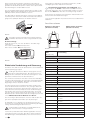
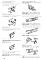
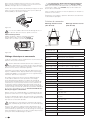
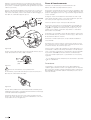
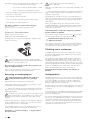
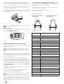
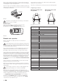
A frame height of at least 140 mm is required at the level of
the tyre hub / tyre centre in the range of 250 mm from the
outer edge of the tyre.
Approval
min. 140
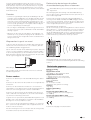
The Truma Mover® XT / XT2 has design approval, and a
“general operating permit” (ABE) has been issued for Germany.
Acceptance by a vehicle expert is not required (except when installing the low chassis kit). The general operating permit (ABE)
must be kept in the vehicle.
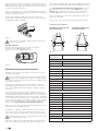
Fig. 8
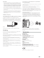
The Mover® XT / XT2 complies with other requirements of
EC Directives and Standards (see Declaration of Conformity).
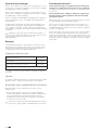
Determining the installation type
When installing the Mover® XT / XT2, the technical and administrative regulations of the country of first registration of
the vehicle must be observed.
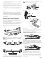
1. Standard installation
Standard installation is used with an U or L-profile chassis and
a frame height of at least 140 mm. No special accessories
are required.
Any modifications made to the device, or the use of any spare
parts or functionally significant accessories other than original
Truma parts, or failure to comply with the contents of the operating and installation instructions invalidates the warranty
and precludes any liability claims. This will also invalidate the
operating permit for the equipment.
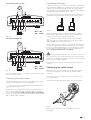
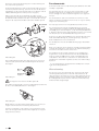
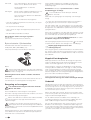
Tools and facilities required
To install the Mover® XT / XT2 you need:
– 8 mm, 10 mm,13 mm and 17 mm socket wrenches, ring
spanners or open-jawed spanners
– Torque wrenches (5 – 50 Nm)
– Cable cutter / crimping tool
– Electric drill / screwdriver / keyhole saw, diameter 25 mm
– 2-tonne trolley jack and suitable support trestles
– Adequate lighting
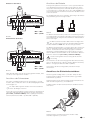
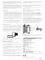
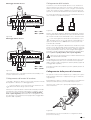
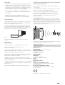
Minimum installation dimensions
A distinction is made between L-profile and U-profile
frames as shown in the illustration.
L-profile
Fig. 6
max. 20
Caravan floor
U-profile
min 250
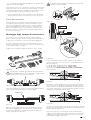
2. Installation on chassis with U or L-profile with a
frame height of between 110 and less than 140 mm
In order to compensate for height, the 30 mm spacer set (for
frame heights down to 110 mm) or the 60 mm spacer set
(for frame heights of less than 110 mm down to 80 mm) is
required.
3. Installation on chassis with U or L profiles with a
frame height of less than 80 mm
If the chassis has a frame height of less than 80 mm, a low
chassis kit must be fitted to compensate for the height.
If a low chassis kit is used in Germany, acceptance by a vehicle expert is required.
4. For the AL-KO Vario III / AV chassis with a frame thickness
of less than 2.8 mm it is essential to use the AL-KO Vario III /
AV installation kit as a reinforcement.
5. For attachment in front of the axle on the AL-KO
chassis M with adjustable beams
In order to compensate for overlapping frame edges, the
AL-KO Chassis M adapter set must be used.
6. For attachment in front of the axle on the AL-KO
chassis M with continuous frame
In order to compensate for overlapping frame edges, the
AL-KO Chassis M adapter set must be used.
7. Installation on Eriba Touring chassis
It is essential to use the Eriba Touring mounting set for the
Eriba Touring chassis.
21