1
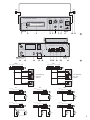
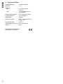
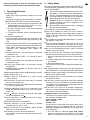
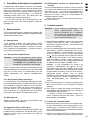
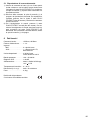
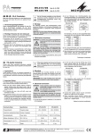
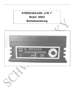
ELA-VERSTÄRKER MIT KASSETTENSPIELER
PA AMPLIFIER WITH CASSETTE PLAYER
PA-120T
Best.-Nr. 17.1130
BEDIENUNGSANLEITUNG
INSTRUCTION MANUAL
MODE D’EMPLOI
ISTRUZIONI PER L’USO
MANUAL DE INSTRUCCIONES
VEILIGHEIDSVOORSCHRIFTEN
SIKKERHEDSOPLYSNINGER
SÄKERHETSFÖRESKRIFTER
TURVALLISUUDESTA
®
D
A
CH
F
B
CH
E
Bevor Sie einschalten ...
GB
Wir wünschen Ihnen viel Spaß mit Ihrem
neuen Gerät von MONACOR. Dabei soll
Ihnen diese Bedienungsanleitung helfen alle
Funktionsmöglichkeiten kennen zu lernen.
Die Beachtung der Anleitung vermeidet
außerdem Fehlbedienungen und schützt Sie
und Ihr Gerät vor eventuellen Schäden durch
unsachgemäßen Gebrauch.
Den deutschen Text finden Sie auf den
Seite 4 – 6.
Avant toute mise en service ...
We wish you much pleasure with your new
unit by MONACOR. With these operating
instructions you will be able to get to know all
functions of the unit. By following these
instructions false operations will be avoided,
and possible damage to you and your unit
due to improper use will be prevented.
You will find the English text on the pages
7 – 9.
I
Nous vous remercions d’avoir choisi un
appareil MONACOR et vous souhaitons
beaucoup de plaisir à l’utiliser. Cette notice a
pour objectif de vous aider à mieux connaître
les multiples facettes de l’appareil et à vous
éviter toute mauvaise manipulation.
La version française se trouve pages 10 – 12.
Antes de cualquier instalación ...
Tenemos de agradecerle el haber adquirido
un equipo MONACOR y le deseamos un
agradable uso. Este manual quiere ayudarle
a conocer las multiples facetas de este
equipo y evitar cualquier uso inadecuado.
Before you switch on ...
Prima di accendere ...
Vi auguriamo buon divertimento con il Vostro
nuovo apparecchio MONACOR. Le istruzioni
per l’uso Vi possono aiutare a conoscere
tutte le possibili funzioni. E rispettando
quanto spiegato nelle istruzioni, evitate di
commettere degli errori, e così proteggete
Voi stessi, ma anche l’apparecchio, da eventuali rischi per uso improprio.
Il testo italiano lo potete trovare alle pagine
13 – 15.
NL
B
La versión española se encuentra en las
páginas 16 – 18.
Voordat u inschakelt ...
Wij wensen u veel plezier met uw nieuw toestel van MONACOR. Lees de veiligheidsvoorschriften, alvorens het toestel in gebruik te
nemen. Door de veiligheidsvoorschriften op
te volgen zal een slechte werking vermeden
worden, en zal een eventueel letsel aan uzelf
en schade aan uw toestel tengevolge van
onzorgvuldig gebruik worden voorkomen.
U vindt de veiligheidsvoorschriften op pagina
20.
DK
Inden De tænder for apparatet ...
Vi ønsker Dem god fornøjelse med Deres
nye MONACOR apparat. Læs oplysningerne
for en sikker brug af apparatet før ibrugtagning. Følg sikkerhedsoplysningerne for at
undgå forkert betjening og for at beskytte
Dem og Deres apparat mod skade på grund
af forkert brug.
Sikkerhedsoplysningerne finder De på side
20.
FIN
Ennen virran kytkemistä …
Toivomme, että uusi MONACOR-laitteesi tuo
sinulle paljon iloa ja hyötyä. Ole hyvä ja lue
käyttöohjeet ennen laitteen käyttöönottoa.
Luettuasi käyttöohjeet voit käyttää laitetta
turvallisesti ja vältyt laitteen väärinkäytöltä.
Käyttöohjeet löydät sivulta 21.
2
S
Förskrift
Vi önskar dig mycket nöje med din nya enhet
från MONACOR. Läs gärna säkerhetsinstruktionerna innan du använder enheten.
Genom att följa säkerhetsinstruktionerna kan
många problem undvikas, vilket annars kan
skada enheten.
Du finner säkerhetsinstruktionerna på sidan
21.
2x
2x
PA-120T PA MIXING AMPLIFIER
MIC 2
MIC 1
AUX/TAPE
ON
10
0
PLAY
10
0
10
0
AUTO STOP CASSETTE
FF
POWER
EJECT
MIC 2
MIC 1
1
2
3
4
5 6
7 8
9
10 11
1
ON
USE
12 V‡ /1.5 A
– COM 4 Ω 8 Ω 16 Ω 70 V 100 V
B
F
+
12 V‡
230 V~ / 50 Hz
L
R
AUX
12
13
14
15 16
17 18 19
100 V
– COM 4 Ω 8 Ω 16 Ω 70 V 100 V
B
12 V‡ /1.5 A
– COM 4 Ω 8 Ω 16 Ω 70 V 100 V
+
3b
+
+
100 V
-
70V
-
max. Belastung
max. load
15W RMS
+
100 V
-
+
+
70V
-
8Ω
– COM 4 Ω 8 Ω 16 Ω 70 V 100 V
B
16 Ω
12 V‡ /1.5 A
+
– COM 4 Ω 8 Ω 16 Ω 70 V 100 V
B
4a
+
– COM 4 Ω 8 Ω 16 Ω 70 V 100 V
6a
-
+
8Ω
-
8Ω
– COM 4 Ω 8 Ω 16 Ω 70 V 100 V
B
+
– COM 4 Ω 8 Ω 16 Ω 70 V 100 V
-
B
12 V‡ /1.5 A
+
– COM 4 Ω 8 Ω 16 Ω 70 V 100 V
5b
+
8Ω
+
8Ω
-
16 Ω
16 Ω
12 V‡ /1.5 A
4b
+
B
+
4Ω
4Ω
12 V‡ /1.5 A
-
12 V‡ /1.5 A
5a
+
-
max. Belastung
max. load
15W RMS
+
70V
-
100 V
-
4Ω
12 V‡ /1.5 A
+
2
B
3a
+
21
70V
12 V‡ /1.5 A
+
20
6b
+
4Ω
-
B
+
4Ω
-
+
8Ω
-
8Ω
3
D
A
Bitte klappen Sie die Seite 3 heraus. Sie sehen
dann immer die beschriebenen Bedienelemente
und Anschlüsse.
CH
1
Übersicht der Bedienelemente
1 Kontrollanzeige
leuchtet, wenn eine Musikkassette abgespielt oder
vorgespult wird
erlischt, wenn das Kassettenende erreicht ist
2 Taste PLAY/FF/EJECT für den Kassettenspieler
a Sobald eine Musikkassette in den Schacht (3)
gesteckt wird, springt die Taste ganz heraus und
die Kassette wird abgespielt.
b Zum Vorspulen die Taste bis zur Hälfte hineindrücken (rastet ein).
c Zum Herauswerfen der Kassette die Taste ganz
hineindrücken.
3 Kassettenschacht
Die Musikkassette mit der offenen Seite nach
rechts und mit der leeren Bandspule nach hinten
zeigend hineinstecken.
4 Lautstärkeregler AUX/TAPE für den Kassettenspieler und für ein an den Buchsen AUX (15) angeschlossenes Audiogerät
Hinweis: Entweder den Kassettenspieler betreiben
oder das angeschlossene Gerät. Anderenfalls sind
beide Signale zu hören.
5 Lautstärkeregler MIC 1 für ein an der Buchse
MIC 1 (6) angeschlossenes Mikrofon
6 6,3-mm-Klinkenbuchse (asym.) MIC 1 zum Anschluss eines Mikrofons
7 Lautstärkeregler MIC 2 für ein an der Buchse
MIC 2 (8) angeschlossenes Mikrofon
8 6,3-mm-Klinkenbuchse (asym.) MIC 2 zum Anschluss eines zweiten Mikrofons
9 Netzschalter POWER zum Ein- und Ausschalten,
wenn das Gerät mit 230 V~ betrieben wird
10 Montagebügel zur Befestigung des Verstärkers
unter eine Konsole
11 Montageschrauben (4 x)
12 Netzanschlussleitung zum Anschluss an eine
Steckdose (230 V~/50 Hz)
13 Sicherungshalter; eine durchgebrannte Sicherung
nur durch eine gleichen Typs ersetzen
14 Klemmschraube für einen eventuellen Masseanschluss (z. B. bei Brummproblemen)
15 Cinch-Eingangsbuchsen AUX für den Anschluss
eines Audiogerätes mit Line-Ausgang (z. B. Tuner,
CD-Spieler, Mischpult etc.)
16 Schalter 12 V zum Ein- und Ausschalten, wenn
der Verstärker mit 12 V betrieben wird
17 Schraubanschlüsse für den Betrieb mit 12 V oder
zur Notstromversorgung
18 Masseanschluss für den/die Lautsprecher
19 Schraubanschlüsse für Niederohm-Lautsprecher
(Impedanz 4 Ω, 8 Ω oder 16 Ω)
4
20 Schraubanschlüsse für ELA-Lautsprecher, die mit
100-V- oder 70-V-Technik arbeiten
21 Schutzkappe für die Schraubanschlüsse
Der Verstärker darf nicht ohne die Schutzkappe
betrieben werden!
2
Hinweise für den sicheren Gebrauch
Dieses Gerät entspricht der Richtlinie für elektromagnetische Verträglichkeit 89/336/EWG und der
Niederspannungsrichtlinie 73/23/EWG.
Das Gerät wird mit lebensgefährlicher Netzspannung (230 V~) versorgt. Nehmen Sie deshalb niemals selbst Eingriffe im Gerät vor.
Durch unsachgemäßes Vorgehen besteht die
Gefahr eines elektrischen Schlages. Außerdem erlischt beim Öffnen des Gerätes jeglicher
Garantieanspruch.
Vorsicht! Im Betrieb liegt an den Lautsprecheranschlüssen (20) berührungsgefährliche Spannung an.
Alle Anschlüsse nur bei ausgeschaltetem
Gerät vornehmen bzw. verändern.
Beachten Sie auch unbedingt die folgenden Punkte:
● Verwenden Sie das Gerät nur im Innenbereich.
Schützen Sie es vor Tropf- und Spritzwasser, hoher
Luftfeuchtigkeit und Hitze (zulässiger Einsatztemperaturbereich 0–40 °C).
● Stellen Sie keine mit Flüssigkeit gefüllten Gefäße,
z. B. Trinkgläser, auf das Gerät.
● Die in dem Gerät entstehende Wärme muss durch
Luftzirkulation abgegeben werden. Decken Sie darum die Lüftungsöffnungen des Gehäuses nicht ab.
● Stecken Sie nichts durch die Lüftungsöffnungen!
Dabei kann es zu einem elektrischen Schlag kommen.
● Nehmen Sie das Gerät nicht in Betrieb bzw. ziehen
Sie sofort den Netzstecker aus der Steckdose,
wenn:
1. sichtbare Schäden am Gerät oder an der Netzanschlussleitung vorhanden sind,
2. nach einem Sturz oder Ähnlichem der Verdacht
auf einen Defekt besteht,
3. Funktionsstörungen auftreten.
Geben Sie das Gerät in jedem Fall zur Reparatur in
eine Fachwerkstatt.
● Eine beschädigte Netzanschlussleitung darf nur
durch den Hersteller oder eine autorisierte Fachwerkstatt ersetzt werden.
● Ziehen Sie den Netzstecker nie an der Zuleitung aus
der Steckdose.
● Verwenden Sie für die Reinigung nur ein trockenes,
weiches Tuch, auf keinen Fall Chemikalien oder
Wasser.
● Wird das Gerät zweckentfremdet, falsch angeschlossen, nicht richtig bedient, überlastet oder
nicht fachgerecht repariert, kann für eventuelle
Schäden keine Haftung übernommen werden.
● Soll das Gerät endgültig aus dem Betrieb genommen werden, übergeben Sie es zur Entsorgung
einem örtlichen Recyclingbetrieb.
B
3
Einsatz- und Aufstellmöglichkeiten
Der ELA-Verstärker PA-120T ist speziell für den Einsatz in kleinen Beschallungsanlagen konzipiert. Es
lassen sich zwei Mikrofone anschließen und ein Gerät
mit Line-Ausgang (z. B. CD-Spieler, Tuner, Mischpult
etc.). Der eingebaute Kassettenspieler kann z. B. für
die Beschallung mit Hintergrundmusik genutzt werden.
Der PA-120T lässt sich als Tischgerät frei aufstellen
oder mit dem Montagebügel (10) unter eine Konsole
schrauben.
4
Verstärker anschließen
Alle Anschlüsse sollten nur durch eine qualifizierte
Fachkraft und unbedingt bei ausgeschaltetem Verstärker vorgenommen werden.
4.1 Lautsprecher
Es können ELA-Lautsprecher, die mit 100-V- oder 70-VTechnik arbeiten (Abb. 3a und 3b), oder NiederohmLautsprecher (Abb. 4a – 6b) angeschlossen werden.
Zum Anschluss die Schutzkappe (21) abschrauben.
4.1.1 ELA-Lautsprecher
Vorsicht! Bei ELA-Lautsprechern (Abb. 3a und 3b)
darf die Gesamtbelastung durch die Lautsprecher nicht mehr als 15 W Sinus
betragen, sonst wird der Verstärker überlastet und eventuell beschädigt.
Die Lautsprecher an die entsprechenden Lautsprecherklemmen (20) für den Pluspol und COM (18) für den
Minuspol anschließen. Der Plusanschluss der Lautsprecherkabel ist immer besonders gekennzeichnet.
4.1.2 Niederohm-Lautsprecher
Die Abb. 4a bis 6b zeigen verschiedene Möglichkeiten, einen oder zwei Lautsprecher mit entsprechender
Impedanz anzuschließen. Den oder die Lautsprecher
an die Klemme COM (18) für den Minuspol und an
einer der Impedanz entsprechenden Klemme (19) für
den Pluspol anschließen. Der Plusanschluss der Lautsprecherkabel ist immer besonders gekennzeichnet.
4.2 Mikrofone
An die Buchse MIC 1 (6) und/oder an die Buchse
MIC 2 (8) je ein Mikrofon anschließen.
4.3 Audiogerät mit Line-Ausgang
Wird der eingebaute Kassettenspieler nicht genutzt,
kann über den Eingang AUX (15) ein Gerät mit LineAusgang (z. B. CD-Spieler, Tuner, Mischpult etc.)
betrieben werden.
4.4 Strom- und Notstromversorgung
Für einen Dauerbetrieb mit Netzausfallsicherung an
die Klemmen „+” und „-” (17) einen 12-V-Akkumulator
anschließen. Diese Klemmen können auch angeschlossen werden, wenn zur Stromversorgung nur
eine 12-V-Quelle (Akku, KFZ-Bordnetz) vorhanden ist.
Zum Schluss den Netzstecker des Anschlusskabels (12) in eine Steckdose (230 V~/50 Hz) stecken.
5
Bedienung
Achtung! Vor dem Einschalten die Schutzkappe
(21) unbedingt wieder festschrauben.
Ohne sie darf der Verstärker nicht betrieben werden! Bei Berührung der Anschlüsse (20) besteht die Gefahr eines
elektrischen Schlages.
D
A
CH
1) Vor dem Einschalten alle drei Regler AUX/TAPE
(4), MIC 1 (5) und MIC 2 (7) ganz nach links auf
Null drehen. Dadurch werden Einschaltgeräusche
vermieden.
2) Bei Betrieb mit 230-V-Netzspannung den Verstärker mit dem Schalter POWER (9) einschalten. Bei
angeschlossener 12-V-Notstromversorgung zusätzlich den Schalter 12 V (16) in die Position ON
schalten. Wird das Gerät nur mit 12 V versorgt,
lediglich den Schalter 12 V betätigen. Bei eingeschaltetem Gerät leuchtet die Betriebsanzeige über
dem Schalter POWER.
Hinweis: Ist eine Notstromversorgung angeschlossen, ist der Verstärker immer in Betrieb. Mit der
Taste POWER läßt sich dann lediglich zwischen
Netzversorgung und Notstromversorgung umschalten. Für den normalen Betrieb mit der Taste
POWER auf Netzversorgung schalten (Position
ON). Bei einem Netzausfall schaltet der Verstärker
dann automatisch auf die Notstromversorgung um.
3) Für Mikrofondurchsagen den Regler MIC 1 (5) und/
oder MIC 2 (7) entsprechend der gewünschten
Lautstärke aufdrehen.
4) Zur Einstellung der Lautstärke des Kassettenspielers oder eines an den Buchsen AUX (15) angeschlossenen Gerätes den Regler AUX/TAPE (4)
aufdrehen.
Beim Betrieb des eingebauten Kassettenspielers muss das angeschlossene Gerät ausgeschaltet sein. Anderenfalls sind beide Signale zu hören.
5.1 Musikkassette abspielen
1) Die Kassette mit der offenen Seite nach rechts und
mit der leeren Bandspule nach hinten zeigend in
den Schacht (3) hineinstecken. Die Taste PLAY/FF/
EJECT (2) springt heraus. Die Kontrollanzeige (1)
über der Taste leuchtet und die Kassette wird abgespielt.
2) Am Ende der Kassette erlischt die Kontrollanzeige
(1) und die Wiedergabe stoppt. Zum Auswerfen der
Kassette die Taste PLAY/FF/EJECT ganz hineindrücken (rastet ein). Die Kassette umdrehen und
wieder hineinstecken.
3) Um die Kassette vorzuspulen, die Taste PLAY/FF/
EJECT bis zur Hälfte hineindrücken (rastet ein).
Zum Beenden des Vorspulens die Taste PLAY/FF/
EJECT etwas drücken, so dass sie wieder ausrastet. Ist die Kassette ganz bis zum Ende gespult,
erlischt die Kontrollanzeige (1) ebenfalls.
5
D
6
A
Ausgangsleistung: . . . . . . 15 WRMS, 25 WMAX
CH
Technische Daten
Klirrfaktor: . . . . . . . . . . . . < 1 %
Eingänge
MIC: . . . . . . . . . . . . . . . 2 x 6,3-mm-Klinke,
5 mV/1 Ω
AUX: . . . . . . . . . . . . . . 1 x Cinch-Buchsen L/R,
80 mV/25 kΩ
Lautsprecherausgang: . . . 4/8/16 Ω oder 70 /100 V
Frequenzbereich: . . . . . . . 100 – 15 000 Hz
Störabstand: . . . . . . . . . . > 60 dB
Stromversorgung: . . . . . . 230 V~/50 Hz/40 VA oder
12 V /1,5 A
Einsatztemperatur: . . . . . 0 – 40 °C
Abmessungen (B x H x T): 245 x 78 x 223 mm
Gewicht: . . . . . . . . . . . . . . 3,4 kg
Laut Angaben des Herstellers.
Änderungen vorbehalten.
6
Please unfold page 3. Then you can always see the
operating elements and connections described.
1
Operating Elements
1 Indicating LED
lights up if a music cassette is played or is on fast
forward
extinguishes if the end of the cassette is reached
2 Button PLAY/FF/EJECT for the cassette player
a As soon as a music cassette is inserted into the
compartment (3), the button jumps out completely and the cassette is played.
b For fast forward, press in the button half-way
(locks into place).
c To eject the cassette, press in the button completely.
3 Cassette compartment
Insert the music cassette with the open side to the
right and with the blank tape spool pointing to the
rear.
4 Volume control AUX/TAPE for the cassette player
and for an audio unit connected to jacks AUX (15)
Note: Either operate the cassette player or the
connected unit. Otherwise both signals are
audible.
5 Volume control MIC 1 for a microphone connected
to jack MIC 1 (6)
6 6.3 mm jack (unbal.) MIC 1 to connect a microphone
7 Volume control MIC 2 for a microphone connected
to jack MIC 2 (8)
8 6.3 mm jack (unbal.) MIC 2 to connect a second
microphone
9 POWER switch to switch on and off if the unit is
operated with 230 V~
10 Mounting bracket to fix the amplifier below a console
11 Mounting screws (4 x)
12 Mains cable for connection to a mains socket
(230 V~/50 Hz)
13 Fuse holder; a blown fuse must only be replaced
by one of the same type
14 Clamping screw for a possible ground connection
(e. g. for hum problems)
15 Phono input jacks AUX for the connection of an
audio unit with line output (e. g. tuner, CD player,
mixer, etc.)
16 12 V switch for switching on and off if the amplifier is operated with 12 V
17 Screw terminals for operation with 12 V or emergency power supply
18 Ground terminal for the speaker/s
19 Screw terminals for low impedance speakers
(impedance 4 Ω, 8 Ω, or 16 Ω)
20 Screw terminals for PA speakers which operate
with 100 V or 70 V technique
21 Protection cover for the screw terminals
The amplifier must not be operated without protection cover!
2
Safety Notes
GB
This unit corresponds to the directive 89/336/EEC for
electromagnetic compatibility and to the low voltage
directive 73/23/EEC.
The unit is supplied with hazardous mains voltage (230 V~). Leave servicing to skilled personnel only. Inexpert handling may cause an electric shock hazard. Furthermore, any guarantee
claim will expire if the unit has been opened.
Caution! There is a hazard of contact at the
speaker terminals (20) with a dangerous voltage during operation.
All connections must only be made or changed
with the unit switched off.
It is essential to observe the following items:
● The unit is suitable for indoor use only. Protect it
against dripping water and splash water, high humidity, and heat (admissible ambient temperature
range 0 – 40 °C).
● Do not place any vessels filled with liquid, e. g. drinking glasses, on the unit.
● The heat being generated in the monitor has to be
removed via air circulation. Therefore, the air vents
at the housing must not be covered with any objects.
● Do not insert anything into the air vents! This could
result in an electric shock.
● Do not set the unit into operation, and immediately
disconnect the mains plug from the mains socket if
1. there is visible damage to the unit or to the mains
cable,
2. a defect might have occurred after a drop or similar accident,
3. there are malfunctions.
The unit must in any case be repaired by skilled personnel.
● A damaged mains cable must only be replaced by
the manufacturer or by authorized, skilled personnel.
● Never pull the mains cable to disconnect the mains
plug from the mains socket.
● For cleaning only use a dry, soft cloth, by no means
chemicals or water.
● If the unit is used for purposes other than originally
intended, if it is not connected or operated correctly,
overloaded, or not repaired in an expert way, there is
no liability for possible damage.
● If the unit is to be put out of operation definitively,
take it to a local recycling plant for disposal which is
not harmful to the environment.
● Important for U. K. Customers!
The wires in this mains lead are coloured in accordance with the following code:
green/yellow = earth
blue = neutral
brown = live
As the colours of the wires in the mains lead of this
appliance may not correspond with the coloured
markings identifying the terminals in your plug, proceed as follows:
1. The wire which is coloured green and yellow
must be connected to the terminal in the plug
which is marked with the letter E or by the earth
B
7
GB
symbol , or coloured green or green and yellow.
2. The wire which is coloured blue must be connected to the terminal which is marked with the
letter N or coloured black.
3. The wire which is coloured brown must be connected to the terminal which is marked with the
letter L or coloured red.
Warning – This appliance must be earthed.
3
Possibilities of Application and
Installation
The PA amplifier PA-120T is especially designed for
use in small PA systems. Two microphones and a unit
with line output (e. g. CD player, tuner, mixer, etc.) can
be connected. The installed cassette player can e. g.
be used for PA applications with background music.
The PA-120T can be placed as a table top unit or be
screwed with the mounting bracket (10) below a console.
4
Connecting the Amplifier
All connections should only be made by qualified personnel and in any case with the amplifier switched off.
4.1 Speakers
PA speakers which operate with 100 V or 70 V technique (figs. 3a and 3b) or low impedance speakers
(figs. 4a – 6b) can be connected. For the connection
screw off the protection cover (21).
4.1.1 PA speakers
Caution! In case of PA speakers (figs. 3a and 3b)
the total load by the speakers must not
exceed 15 WRMS, otherwise the amplifier
will be overloaded and possibly damaged.
Connect the speakers to the corresponding speaker
terminals (20) for the positive pole and COM (18) for
the negative pole. The positive connection of the
speaker cables is always especially coded.
4.1.2 Low impedance speakers
Figs. 4a to 6b show the different possibilities to connect one or two speakers with corresponding impedance. Connect the speaker/s to the terminal COM
(18) for the negative pole and to a terminal corresponding to the impedance (19) for the positive pole. The
positive connection of the speaker cables is always
especially coded.
4.2 Microphones
Connect one microphone each to jack MIC 1 (6)
and/or to jack MIC 2 (8).
8
4.3 Audio unit with line output
If the built-in cassette recorder is not used, it is possible to operate a unit with line output (e. g. CD player,
tuner, mixer, etc.) via the input AUX (15).
4.4 Power supply and emergency power
supply
For a permanent operation with power failure back-up
connect a 12 V rechargeable battery to the terminals
“+” and “-” (17). These terminals can also be connected if only a 12 V source (rechargeable battery, electric system of a car) is available for the power supply.
Finally connect the mains plug of the cable (12) to a
mains socket (230 V~/50 Hz).
5
Operation
Attention! Prior to switching-on, tightly screw on the
protection cover (21) in any case. Without
it the amplifier must not be operated!
When touching the connections (20) there
is a danger of an electric shock.
1) Prior to switching-on, set all three controls AUX/
TAPE (4), MIC 1 (5), and MIC 2 (7) to the left stop
to zero. Thus, switching-on noise will be prevented.
2) For the operation with 230 V mains voltage switch
on the amplifier with the POWER switch (9). With
the 12 V emergency power supply connected, additionally set the 12 V switch (16) to position ON. If
the unit is only supplied with 12 V, only actuate the
12 V switch. With the unit switched on, the power
LED above the POWER switch lights up.
Note: If an emergency power supply is connected,
the amplifier is always in operation. With the
POWER button it is only possible to switch over
between mains supply and emergency power supply. For normal operation switch the POWER button
to mains supply (position ON). In case of mains failure the amplifier automatically switches to emergency power supply.
3) For microphone announcements turn up the control
MIC 1 (5) and/or MIC 2 (7) according to the desired
volume.
4) To adjust the volume of the cassette player or of
one of the units connected to the jacks AUX (15),
turn up the control AUX/TAPE (4).
When operating the installed cassette player,
the connected unit must be switched off. Otherwise
both signals can be heard.
5.1 Playing a music cassette
1) Insert the cassette with the open side to the right
and with the blank tape spool pointing to the rear
into the compartment (3). The button PLAY/FF/
EJECT (2) jumps out. The indicating LED (1) above
the button lights up and the cassette is played.
2) At the end of the cassette the indicating LED (1)
extinguishes and the replay stops. To eject the cassette, press in the button PLAY/EFF/EJECT com-
pletely (locks into place). Turn over the cassette
and insert it into the compartment again.
3) For fast forward, press in button PLAY/EFF/EJECT
half-way (locks into place). To stop the fast forward,
slightly press button PLAY/FF/EJECT so that it is
released again. If the end of the cassette is reached,
the indicating LED (1) likewise extinguishes.
6
GB
Specifications
Output power: . . . . . . . . . 15 WRMS, 25 WMAX
THD: . . . . . . . . . . . . . . . . < 1 %
Inputs
MIC: . . . . . . . . . . . . . . 2 x 6.3 mm jack,
5 mV/1 Ω
AUX: . . . . . . . . . . . . . . 1 x phono jacks L/R,
80 mV/25 kΩ
Speaker output: . . . . . . . . 4/8/16 Ω or 70 /100 V
Frequency range:: . . . . . . 100 – 15 000 Hz
S/N ratio: . . . . . . . . . . . . . > 60 dB
Power supply: . . . . . . . . . 230 V~/50 Hz/40 VA
or 12 V /1.5 A
Ambient temperature: . . . 0 – 40 °C
Dimensions (W x H x D): . 245 x 78 x 223 mm
Weight: . . . . . . . . . . . . . . . 3.4 kg
According to the manufacturer.
Subject to change.
9
F
B
Ouvrez le présent livret page 3 de manière à visualiser les éléments et branchements.
CH
1
Eléments et branchements
1 LED de contrôle :
brille lorsqu’une cassette est lue ou bobinée
(avance rapide)
s’éteint lorsque la fin de la cassette est atteinte
2 Touche PLAY/FF/EJECT pour le lecteur de cassettes
a Dès qu’une cassette est insérée dans le compartiment cassette (3), la touche est entièrement
sortie, la cassette est lue.
b Pour bobiner la cassette, enfoncez la touche à
moitié (cran d’enclenchement).
c Pour éjecter la cassette, enfoncez entièrement
la touche.
3 Compartiment cassettes : la cassette doit être
insérée, la partie bande vers la droite, la partie vide
d’enroulement de la cassette vers l’arrière.
4 Potentiomètre de réglage de volume AUX/TAPE
pour le lecteur de cassettes et pour un appareil
audio relié aux prises AUX (15).
Conseil : faites fonctionner soit le lecteur de cassettes soit l’appareil relié. Dans le cas contraire, les
deux signaux sont audibles.
5 Potentiomètre de réglage de volume MIC 1 pour un
micro relié à la prise MIC 1 (6)
6 Prise jack 6,35 (asymétrique) MIC 1 pour brancher
un micro
7 Potentiomètre de réglage de volume MIC 2 pour un
micro relié à la prise MIC 2 (8)
8 Prise jack 6,35 (asymétrique) MIC 2 pour brancher
un second micro
9 Interrupteur POWER Marche/Arrêt lorsque l’appareil fonctionne avec une tension d’alimentation
230 V~.
10 Etrier de montage pour fixer l’amplificateur sous
une console
11 Vis de montage (x 4)
12 Cordon secteur à relier à une prise secteur 230 V~/
50 Hz
13 Porte-fusible : tout fusible endommagé doit être
exclusivement remplacé par un fusible de même
type
14 Vis pour un éventuel branchement masse (p. ex.
en cas de problème de ronflement)
15 Prises d’entrée RCA AUX pour brancher un
appareil audio à sortie Ligne (p. ex. tuner, lecteur
CD, table de mixage ...)
16 Interrupteur 12 V
pour Marche/Arrêt lorsque
l’amplificateur fonctionne avec une tension d’alimentation 12 V
17 Bornes à vis pour le fonctionnement 12 V ou l’alimentation de secours
18 Branchement masse pour le/les haut-parleur(s)
19 Bornes à vis pour des haut-parleurs basse impédance (impédance 4 Ω, 8 Ω ou 16 Ω)
10
20 Bornes à vis pour les haut-parleurs Public Adress
fonctionnant en ligne 100 V ou 70 V
21 Cache de protection pour les bornes ; l’amplificateur ne doit pas fonctionner sans ce cache de protection
2
Conseils d’utilisation et de sécurité
Cet appareil répond à la norme 89/336/CEE relative à
la compatibilité électromagnétique (CE) et à la norme
73/23/CEE relative aux appareils basse tension.
Cet amplificateur est alimenté par une tension
en 230 V~. Ne touchez jamais l’intérieur de
l’appareil car, en cas de mauvaise manipulation, vous pourriez subir une décharge électrique mortelle. En outre, l’ouverture de l’appareil
rend tout droit à la garantie caduque.
Attention : pendant le fonctionnement, une
tension dangereuse est présente aux bornes
haut-parleurs (20) .
Tout branchement ne peut être effectué ou
modifié que si l’appareil est éteint.
Respectez scrupuleusement les points suivants :
● L’appareil n’est conçu que pour une utilisation en
intérieur. Protégez-le des éclaboussures, de tout
type de projections d’eau, de l’humidité et de la chaleur (température ambiante admissible 0 – 40 °C).
● En aucun cas, vous ne devez poser d’objet contenant du liquide ou un verre sur l’appareil.
● La chaleur dégagée par l’appareil doit être correctement évacuée par la circulation d’air. En aucun cas,
les ouïes de ventilation de l’amplificateur ne doivent
être obturées.
● Ne faites rien tomber dans les ouïes de ventilation,
vous pourriez vous électrocuter.
● Ne faites jamais fonctionner l’amplificateur et
débranchez-le immédiatement lorsque :
1. des dommages sur l’appareil ou le cordon secteur
apparaissent,
2. après une chute ou accident similaire..., l’appareil
peut présenter un défaut,
3. des dysfonctionnements apparaissent.
Dans tous les cas, les dommages doivent être
réparés par un technicien spécialisé.
● Tout cordon secteur endommagé doit être exclusivement remplacé par le fabricant ou un technicien
habilité.
● Ne débranchez jamais l’appareil en tirant sur le cordon secteur.
● Pour nettoyer l’appareil, utilisez un chiffon sec et
doux, en aucun cas de produits chimiques ou d’eau.
● Nous déclinons toute responsabilité en cas de dommage si l’appareil est utilisé dans un but autre que
celui pour lequel il a été conçu, s’il n’est pas correctement branché, utilisé ou réparé par une personne
habilitée ou s’il y a surcharge.
● Lorsque l’appareil est définitivement retiré du marché, vous devez le déposer dans une usine de recyclage adaptée, locale, pour une élimination non polluante.
B
3
Possibilités d’utilisation et d’installation
L’amplificateur Public Adress PA-120T est spécialement conçu pour une utilisation dans de petites installations de sonorisation. Il est possible de brancher
deux microphones et un appareil à sortie Ligne (p. ex.
lecteur CD, tuner, table de mixage ...). Le lecteur de
cassettes intégré peut, p. ex., être utilisé pour une
sonorisation de musique d’ambiance.
Le PA-120T peut être posé directement sur une
table ou placé sous une console grâce à l’étrier de
montage (10).
4.4 Alimentation secteur et alimentation de
secours
Pour un fonctionnement en continu en cas de coupure
de courant, vous pouvez relier un accumulateur 12 V
aux bornes “+” et “-” (17). Ces bornes peuvent également être utilisées lorsque, pour l’alimentation, uniquement une source 12 V (p. ex. accumulateur, alimentation véhicule) existe.
Reliez enfin le cordon secteur (12) à une prise secteur 230 V~/50 Hz.
5
4
Branchements
Tous les branchements ne doivent être effectués que
par un technicien qualifié et habilité, l’appareil devant
impérativement être éteint.
4.1 Haut-parleurs
Reliez à la prise MIC 1 (6) et/ou à la prise MIC 2 (8)
respectivement un microphone.
5.1 Lecture de cassettes audio
Attention ! Pour des haut-parleurs Public Adress
(schéma 3a et 3b), la charge maximale
pour les haut-parleurs ne doit pas dépasser 15 WRMS sinon l’amplificateur est en
surcharge et pourrait être endommagé.
Reliez les haut-parleurs aux bornes haut-parleurs (20)
correspondantes pour le pôle plus et à la borne COM
(18) pour le pôle moins. Le branchement plus des
câbles haut-parleur est toujours spécifiquement
repéré.
4.1.2 Haut-parleurs basse impédance
Les schémas 4a à 6b présentent différentes possibilités de branchement d’un ou deux haut-parleurs avec
leur impédance respective. Reliez le ou les haut-parleur(s) à la borne COM (18) pour le pôle moins et à
une des bornes (19) correspondant à l’impédance
pour le pôle plus. Le branchement plus des câbles
haut-parleur est toujours spécifiquement repéré.
4.3 Appareil audio à sortie Ligne
Si le lecteur de cassettes intégré n’est pas utilisé, il est
possible de faire fonctionner, via l’entrée AUX (15), un
appareil à sortie Ligne (p. ex. lecteur CD, table de
mixage, tuner...).
CH
Attention ! Avant d’allumer l’amplificateur, vous
devez impérativement revisser le
cache de protection (21) ; l’amplificateur ne doit pas fonctionner sans lui !
Un risque de décharge électrique existe au contact des bornes (20).
4.2 Microphones
4.1.1 Haut-parleurs Public Adress
B
Fonctionnement
1) Avant d’allumer l’appareil, tournez les trois potentiomètres AUX/TAPE (4), MIC 1 (5) et MIC 2 (7)
entièrement à gauche sur zéro ; on évite ainsi tout
bruit fort à l’allumage.
2) Pour un fonctionnement avec une tension d’alimentation 230 V~, allumez l’amplificateur avec l’interrupteur POWER (9). Si l’alimentation de secours
12 V est branchée, mettez, en plus l’interrupteur
12 V (16) sur la position ON. Si l’appareil n’est alimenté que par une tension 12 V, activez uniquement l’interrupteur 12 V . Lorsque l’appareil est
allumé, la LED témoin de fonctionnement située
au-dessus de l’interrupteur POWER, brille.
Conseil : si une alimentation de secours est
connectée, l’amplificateur est toujours en fonctionnement. Avec la touche POWER, vous pouvez
commuter uniquement entre alimentation secteur
et alimentation de secours. Pour un mode de fonctionnement normal, passez, avec la touche
POWER sur alimentation secteur (position ON). En
cas de coupure de courant, l’amplificateur commute automatiquement sur l’alimentation de
secours.
3) Pour des annonces micro, tournez le potentiomètre
MIC 1 (5) et/ou MIC 2 (7) en fonction du volume
souhaité.
4) Pour régler le volume du lecteur de cassettes ou
d’un appareil relié aux prises AUX (15), tournez le
potentiomètre AUX/TAPE (4).
Lorsque le lecteur de cassettes intégré fonctionne, l’appareil relié doit être éteint ; sinon les
deux signaux sont audibles.
Il est possible d’utiliser des haut-parleurs Public
Adress ligne 100 V ou 70 V (schémas 3a et 3b) ou des
haut-parleurs basse impédance (schémas 4a – 6b).
Pour connecter les haut-parleurs, il convient de dévisser le cache de protection (21).
F
1) Placez la cassette, côté ouvert vers la droite et partie vide d’enroulement vers l’arrière dans le compartiment (3). La touche PLAY/FF/EJECT (2) ressort ; la LED de contrôle (1) au-dessus de la touche
brille et la cassette est lue.
2) A la fin de la cassette, la LED (1) s’éteint, la lecture
s’arrête ; pour éjecter la cassette, enfoncez la tou-
11
F
B
CH
che PLAY/FF/EJECT complètement (le cran s’enclenche). Tournez la cassette et replacez-la dans le
compartiment.
3) Pour faire avancer la cassette, enfoncez la touche
PLAY/FF/EJECT jusqu’à la moitié de sa hauteur
(le cran s’enclenche). Pour arrêter l’avance rapide,
enfoncez la touche PLAY/FF/EJECT jusqu’à ce
que la touche ressorte. Si la cassette est bobinée
entièrement jusqu’à la fin, la LED (1) s’éteint également.
6
Caractéristiques techniques
Puissance de sortie : . . . . 15 WRMS, 25 WMAX
Taux de distorsion : . . . . . < 1 %
Entrées
MIC : . . . . . . . . . . . . . . 2 x jack 6,35, 5 mV/1 Ω
AUX : . . . . . . . . . . . . . . 1 x prise RCA G/D,
80 mV/25 kΩ
Sortie haut-parleur : . . . . . 4/8/16 Ω ou 70 /100 V
Bande passante : . . . . . . . 100 – 15 000 Hz
Rapport signal : . . . . . . . . > 60 dB
Alimentation : . . . . . . . . . . 230 V~/50 Hz/40 VA ou
12 V /1,5 A
Température de
fonctionnement : . . . . . . . 0 – 40 °C
Dimensions (L x H x P) : . 245 x 78 x 223 mm
Poids : . . . . . . . . . . . . . . . 3,4 kg
D’après les données du constructeur.
Tout droit de modification réservé.
12
Vi preghiamo di aprire completamente la pagina 3.
Così vedrete sempre gli elementi di comando e i
collegamenti descritti.
1
Elementi di comando
1 Spia di controllo
è accesa durante la riproduzione di una cassetta o
durante l’avvolgimento in avanti;
si spegne alla fine della cassetta
2 Tasto PLAY/FF/EJECT per il lettore di cassette
a Non appena si inserisce una cassetta nel vano
(3), il tasto si sblocca e inizia la riproduzione
b Per avvolgere la cassetta in avanti premere il
tasto a meta (fino allo scatto)
c Per espellere la cassetta premere il tasto fino in
fondo
3 Vano per musicassette
Inserire la cassetta con il lato aperto rivolto a
destra; la bobina vuota deve essere rivolta versa
l’operatore
4 Regolatore volume AUX/TAPE per il lettore di cassette e per un altro apparecchio audio collegato con
le prese AUX (15)
N.B.: Fare funzionare o il lettore di cassette o l’altra
sorgente. Altrimenti si sentono i segnali di entrambi.
5 Regolatore volume MIC 1 per un microfono collegato con la presa MIC 1 (6)
6 Presa jack 6,3 mm (asimm.) MIC 1 per il collegamento di un microfono
7 Regolatore volume MIC 2 per un microfono collegato con la presa MIC 2 (8)
8 Presa jack 6,3 mm (asimm.) MIC 2 per il collegamento di un secondo microfono
9 Interruttore di rete POWER per accendere e spegnere l’apparecchio se funziona con 230 V~
10 Staffa di montaggio per fissare l’amplificatore sotto
una consolle
11 Viti di montaggio (4 x)
12 Cavo rete per il collegamento con una presa di rete
(230 V~/50 Hz)
13 Portafusibile; sostituire un fusibile difettoso con
uno dello stesso tipo
14 Morsetto per un eventuale collegamento di massa
(p. es. nel caso di ronzii)
15 Prese d’ingresso AUX per il collegamento di apparecchi audio con uscita Line (p. es. tuner, lettore
CD, mixer ecc.)
16 Interruttore 12 V per accendere e spegnere l’amplificatore se funziona con 12 V
17 Contatti a vite per il funzionamento a 12 V o per
corrente di emergenza
18 Contatto di massa per altoparlante/i
19 Contatti a vite per altoparlanti a bassa impedenza
(4 Ω, 8 Ω o 16 Ω)
20 Contatti a vite per altoparlanti PA con uscita audio
100 V o 70 V
21 Cappuccio di protezione per i contatti a vite
Non fare funzionare l’amplificatore senza il cappuccio di protezione!
2
Avvertenze di sicurezza
I
Quest’apparecchio è conforme alle direttive CE
89/336/CEE sulla compatibilità elettromagnetica e
73/23/CEE per apparecchi a bassa tensione.
L’apparecchio funziona con tensione di rete di
230 V~. Non intervenire mai al suo interno; la
manipolazione scorretta può provocare delle
scariche pericolose. Se l’apparecchio viene
aperto, cessa ogni diritto di garanzia.
Attenzione! Durante il funzionamento, ai contatti degli altoparlanti (20) è presente una tensione pericolosa al contatto.
Eseguire o modificare tutti i collegamenti solo
l’apparecchio spento.
Durante l’uso si devono osservare assolutamente i
seguenti punti:
● Far funzionare l’apparecchio solo all’interno di locali.
Proteggerlo dall’acqua gocciolante e dagli spruzzi
d’acqua, da alta umidità dell’aria e dal calore (temperatura d’impiego ammessa fra 0 e 40 °C).
● Non depositare sull’apparecchio dei contenitori
riempiti di liquidi, p. es. bicchieri.
● Dev’essere garantita la libera circolazione dell’aria
per dissipare il calore che viene prodotto all’interno
dell’apparecchio. Non coprire in nessun modo le
fessure d’aerazione.
● Non inserire oggetti nelle fessure d’aerazione e non
farci cadere niente. Altrimenti si potrebbe provocare
una scarica elettrica.
● Non mettere in funzione l’apparecchio e staccare
subito la spina rete se:
1. l’apparecchio o il cavo rete presentano dei danni
visibili;
2. dopo una caduta o dopo eventi simili sussiste il
sospetto di un difetto;
3. l’apparecchio non funziona correttamente.
Per la riparazione rivolgersi sempre ad un’officina
competente.
● Il cavo rete, se danneggiato, deve essere sostituito
solo dal costruttore o da un laboratorio autorizzato.
● Staccare il cavo rete afferrando la spina, senza tirare il cavo.
● Per la pulizia usare solo un panno morbido, asciutto;
non impiegare in nessun caso prodotti chimici o
acqua.
● Nel caso d’uso improprio, di collegamenti sbagliati,
d’impiego scorretto, di sovraccarico o di riparazione
scorretta non si assume nessuna responsabilità per
eventuali danni.
● Se si desidera eliminare l’apparecchio definitivamente, consegnarlo per lo smaltimento ad un’istituzione locale per il riciclaggio.
B
13
I
Possibilità di impiego e di collocazione
4.4 Alimentazione e alimentazione di emergenza
L’amplificatore PA-120T è stato realizzato specialmente per l’impiego in piccoli impianti di sonorizzazione. Si possono collegare due microfoni nonché un
apparecchio con uscita Line (p. es. lettore CD, tuner,
mixer ecc.). Il lettore integrato per cassette può essere
usato per sonorizzazioni di fondo.
Il PA-120T può essere collocato liberamente su un
tavolo, e con la staffa di montaggio (10) può essere
montato anche sotto una consolle.
Per il funzionamento permanente protetto contro la
caduta di rete collegare un accumulatore 12 V con i
morsetti “+” e “-” (17). Questi morsetti possono essere
usati anche se per l’alimentazione è disponibile solo
una sorgente 12 V (accumulatore, rete dell’autoveicolo).
Alla fine inserire la spina di rete del cavo (12) in una
presa di rete (230 V~/50 Hz).
3
5. Funzionamento
4
Collegamento dell’amplificatore
Tutti i collegamenti devono essere eseguiti solo da
una persona esperta e qualificata. L’amplificatore
deve assolutamente essere spento.
4.1 Altoparlanti
Si possono collegare altoparlanti PA con uscita audio
100 V o 70 V (figg. 3a e 3b) oppure altoparlanti a bassa
impedenza (figg. 4a – 6b). Per il collegamento svitare il
cappuccio di protezione (21).
4.1.1 Altoparlanti PA
Attenzione! Nel caso di altoparlanti PA (figg. 3a e
3b), la potenza globale degli altoparlanti
non deve superare 15 WRMS per non
sovraccaricare ed eventualmente danneggiare l’amplificatore.
Collegare gli altoparlanti con i relativi morsetti (20) per
il positivo e COM (18) per il negativo. Il positivo dei
cavi è sempre contrassegnato in modo particolare.
4.1.2 Altoparlanti a bassa impedenza
Le figure da 4a a 6b illustrano le diverse possibilità per
collegare uno o due altoparlanti con impedenza adeguata. Collegarli con il morsetto COM (18) per il negativo e per il positivo con uno dei morsetti (19) a
seconda dell’impedenza. Il positivo dei cavi è sempre
contrassegnato in modo particolare.
4.2 Microfoni
Collegare un microfono con la presa MIC 1 (6) e/o con
la presa MIC 2 (8).
4.3 Apparecchio audio con uscita Line
Se il lettore integrato di cassette non viene usato,
all’ingresso AUX (15) si può collegare un apparecchio
con uscita Line (p. es. lettore CD, tuner, mixer, ecc.)
14
Attenzione! Prima di accendere occorre riavvitare
assolutamente il cappuccio di protezione (21). Senza il cappuccio, l’amplificatore non deve essere usato! Toccando i contatti (20) si corre il pericolo
di una scossa elettrica.
1) Prima dell’accensione girare tutti i tre i regolatori
AUX/TAPE (4), MIC 1 (5) e MIC 2 (7) completamente a sinistra sullo zero. In tal modo si evitano i
rumori di commutazione.
2) Nel caso di funzionamento con tensione di rete
230 V~, accendere l’amplificatore con l’interruttore
POWER (9). Se è collegata l’alimentazione di
emergenza a 12 V, portare anche l’interruttore
12 V (16) in posizione ON. Se l’apparecchio deve
funzionare solo con tensione di 12 V basta azionare
l’interruttore 12 V . Se l’apparecchio è acceso, la
spia di controllo sopra l’interruttore POWER è
accesa.
N.B.: Se l’alimentazione di emergenza è collegata,
l’amplificatore è sempre in funzione. Con il tasto
POWER si cambia semplicemente fra alimentazione rete e alimentazione di emergenza. Per il funzionamento normale attivare l’alimentazione rete
con il tasto POWER (posizione ON). In caso di
caduta di rete, l’amplificatore passa automaticamente all’alimentazione di emergenza.
3) Per avvisi fatti con il microfono aprire il regolatore
MIC 1 (5) e/o MIC 2 (7) secondo necessità.
4) Per impostare il volume del lettore integrato di cassette o di un apparecchio collegato con le prese
AUX (15), aprire il regolatore AUX/TAPE (4).
Se viene usato il lettore integrato di cassette,
l’apparecchio collegato deve essere spento. Altrimenti si sentono entrambi i segnali.
5.1 Riproduzione di una musicassetta
I
1) Inserire la cassetta nel vano (3) con il lato aperto
rivolta a destra e con la bobina vuota rivolta verso
l’operatore. Il tasto PLAY/FF/EJECT (2) si sblocca.
La spia di controllo (1) sopra il tasto si accende e la
riproduzione inizia.
2) Alla fine della cassetta, la spia di controllo (1) si
spegne e la riproduzione si arresta. Per espellere la
cassetta premere fino in fondo il tasto PLAY/
FF/EJECT (fino all’incastro). Rivoltare la cassetta e
inserirla di nuovo.
3) Per l’avvolgimento in avanti, premere il tasto
PLAY/FF/EJECT a metà (fino allo scatto). Per terminare l’avvolgimento in avanti esercitare una leggera pressione sul tasto PLAY/FF/EJECT per
sbloccarla. Se la cassetta è arrivata alla fine, anche
la spia di controllo (1) si spegne.
6
Dati tecnici
Potenza d’uscita: . . . . . . . 15 WRMS, 25 WMAX
Fattore di distorsione: . . . < 1 %
Ingressi
MIC: . . . . . . . . . . . . . . . 2 x jack 6,3 mm
AUX: . . . . . . . . . . . . . . 1 x prese cinch L/R,
80 mV/25 kΩ
Uscita altoparlanti: . . . . . . 4/8/16 Ω opp.
uscita audio 70 /100 V
Banda passante: . . . . . . . 100 – 15 000 Hz
Rapporto S/R: . . . . . . . . . > 60 dB
Alimentazione: . . . . . . . . . 230 V~/50 Hz/40 VA opp.
12 V /1,5 A
Temperatura d’esercizio: . 0 – 40 °C
Dimensioni (l x h x p): . . . 245 x 78 x 223 mm
Peso: . . . . . . . . . . . . . . . . 3,4 kg
Dati forniti dal produttore.
Con riserva di modifiche tecniche.
15
E
Abrir el libro página 3 de manera a visualizar los
elementos y las conexiones.
20 Bornes atornillados para los altavoces PA que funcionan en línea 100 V o 70 V.
21 Tapa de protección para los bornes; el amplificador
no debe funcionar sin la tapa de protección!
1
Elementos
1 LED de control:
brilla cuando una cassette audio está “leída” o
rebobinada (avance rápido)
se apaga cuando el fin de la cassette está alcanzada.
2 Tecla PLAY/FF/EJECT para el cassette.
a En cuanto una cassette audio está insertada en
el compartimiento (3), la tecla salta completamente, la cassette está leída.
b Para rebobinar, apretar la tecla a mitad (el
muelle se engancha).
c Para sacar la cassette, apretar del todo la tecla.
3 Compartimiento: la cassette audio debe insertarse,
la parte banda hacia la derecha, la parte vacía de
enrollamiento de la cassette hacia atrás.
4 Potenciómetro de regulación del volumen AUX/
TAPE para el cassette y para un aparato audio
conectado con las tomas AUX (15).
Consejo: hacer funcionar el cassette o el aparato
conectado. En el caso contrario, las dos señales
son audibles.
2
B
Este amplificador está alimentado por una tensión en 230 V~. No manipular nunca el interior
del aparato, podría en caso de mala manipulación sufrir una descarga eléctrica mortal. Por lo
tanto, la apertura del aparato niega todo derecho a una garantía.
Atención: durante el funcionamiento, una tensión peligrosa esté presente en los bornes de
los altavoces (20).
Toda conexión puede efectuarse o modificarse
solo si el aparato está apagado.
Respetar escrupulosamente los puntos siguientes:
●
5 Potenciómetro de regulación del volumen MIC 1
para un micro conectado con la toma MIC 1 (6)
El aparato está fabricado solo para una utilización
en interior. Protegerlo de las salpicaduras, de todo
tipo de proyecciones de agua, de la humedad et del
calor (temperatura de funcionamiento admisible
0 – 40 °C).
●
6 Toma jack 6,35 (asimétrica) MIC 1 para conectar
un micro.
En ningún caso, dejar un objeto con un contenido
líquido o un vaso sobre el aparato.
●
8 Toma 6,35 (asimétrica) MIC 2 para conectar un
segundo micro.
El calor generado por el aparato debe evacuarse
correctamente por una buena circulación de aire. En
ningún caso, los agujeros de ventilación del amplificador deben obstruirse.
●
9 Interruptor POWER ON/OFF cuando el aparato
funciona con una tensión de alimentación 230 V~.
No hacer caer nunca algo en los agujeros de ventilación, podría sufrir una descarga eléctrica.
●
13 Porta fusible: todo fusible fundido debe ser cambiado únicamente por un fusible de mismo tipo.
No haga nunca funcionar el amplificador y desconectarlo inmediatamente cuando:
1. daños aparecen en el aparato o en el cable de red.
2. después de una caída o accidente similar..., si el
aparato presenta un defecto.
3. disfunciones aparecen.
En todos los casos, los daños deben repararse por
un técnico especializado.
●
14 Tornillo para una eventual conexión masa (p. ej. en
caso de problema de zumbido).
Todo cable de red dañado debe exclusivamente
cambiarse por el fabricante o un técnico habilitado.
●
15 Toma de entrada RCA AUX para conectar un aparato audio a la salida Línea (p. ej. tuner, lector CD,
mesa de mezcla).
No desconectar nunca el aparato tirando del cable
de red.
●
16 Interruptor 12 V para ON/OFF cuando el amplificador funciona con una tensión de alimentación
12 V .
Para limpiar el aparato, utilizar un trapo seco y
blando, en ningún caso limpiarlo con productos químicos o agua.
●
Rechazamos toa responsabilidad en caso de daños
si el aparato está utilizado con otro fin para el cual
ha sido fabricado, si no está correctamente conectado, utilizado o reparado por una persona habilitada o si hay sobrecarga.
●
Cuando el aparato está definitivamente sacado del
servicio, debe depositarlo en una fábrica de reciclaje
adaptada, para una eliminación no contaminante.
7 Potenciómetro de regulación de volumen MIC 2
para un micro conectado a la toma MIC 2 (8).
10 Soporte de montaje parar sujetar el amplificador
bajo una consola.
11 Tornillo de montaje (x 4).
12 Cable de red a conectar con una toma de red
230 V~/50 Hz.
17 Bornes atornillados para el funcionamiento 12 V o
la alimentación de socorro.
18 Conexión masa para él/los altavoces.
19 Bornes atornillados para altavoces baja impedancia (impedancia 4 Ω, 8 Ω o 16 Ω).
16
Consejos de utilización
Este aparato responde a la norma 89/336/CEE relacionada a la compatibilidad electromagnética y a la
norma 73/23/CEE relacionada con los aparatos de
baja tensión.
3
Posibilidad de utilización y de
instalación
El amplificador PA PA-120T está especialmente fabricado para una utilización en pequeñas instalaciones
de sonorización. Es imposible conectar dos micro y un
aparato con salida Línea (p. ej. el lector CD, tuner,
mesa de mezcla). El cassette integrado puede p. ej.,
utilizarse para una sonorización de música de
ambiente.
El PA-120T puede estar situado en una mesa o
bajo una consola por medio de un soporte de montaje
(10).
4
Conexiones
Todas las conexiones deberían efectuarse solo por un
técnico calificado y habilitado, el aparato estando
imperativamente apagado.
4.1 Altavoces
Es posible utilizar altavoces PA línea 100 V o 70 V
(esquema 3a y 3b) o altavoces de baja impedancia
(esquema 4a – 6b). Para la conexión la tapa de protección (21) se tiene que destornillar.
4.1.1 Altavoces PA
¡Atención! Para altavoces PA (esquema 3a y 3b), la
carga máxima para los altavoces no
debe sobrepasar 15 WRMS si no el amplificador estuviese en sobrecarga y podría
ser dañado.
Conectar los altavoces con los bornes altavoces (20)
correspondientes para el polo positivo y a al borne
COM (18) para el polo negativo. La conexión positiva
de los cables altavoces está siempre específicamente
señalada.
4.1.2 Altavoces baja impedancia
Los esquemas 4a a 6b presentan diferentes posibilidades de conexión de un o dos altavoces con su
impedancia respectiva. Conectar el o los altavoces al
borne COM (18) para el polo negativo y a uno de los
borne (19) correspondiente a la impedancia para el
polo positivo. La conexión positiva de los cables altavoces está siempre específicamente señalada.
4.4 Alimentación de red y alimentación de
socorro
E
Para un funcionamiento en continuo en caso de corte
de corriente, puede conectar un acumulador 12 V con
los bornes “+” y “-” (17). Estos bornes pueden también ser utilizados si existe para la alimentación solamente una fuente 12 V (por ejemplo acumulador, alimentación vehículo).
Conectar por fin el cable de red (12) con una toma
de red 230 V~/50 Hz.
5
Funcionamiento
¡Atención! ¡Antes de conectar el amplificador, debe
imperativamente atornillar de nuevo la
tapa de protección (21); el amplificador
no debe funcionar sin ella! Un riesgo de
descarga eléctrica existe al contacto de
los bornes (20).
1) Antes de conectar el aparato, dar vuelta a los tres
potenciómetros AUX/TAPE (4), MIC 1 (5) y MIC 2
(7) hacia la izquierda en posición cero; se evita así
todo ruido fuerte al conectar el aparato.
2) Para un funcionamiento con una tensión de alimentación 230 V~, conectar el amplificador con el
interruptor POWER (9). Si la alimentación de
socorro 12 V está conectada, conectar también el
interruptor 12 V (16) en la posición ON. Si el aparato solo está alimentado por una tensión 12 V,
activar solamente el interruptor 12 V . Cuando el
aparato está conectado, el LED de funcionamiento,
situado por encima del interruptor POWER, brilla.
Consejo: si una alimentación de socorro está
conectada, el amplificador está siempre en funcionamiento. En este caso, con la tecla POWER,
puede conmutar solamente entre alimentación de
red y alimentación de socorro. Para un modo de
funcionamiento normal, pasar, con la tecla POWER
en alimentación de red (posición ON). En caso de
corte de corriente, el amplificador conmuta
automáticamente en la alimentación de socorro.
3) Para anuncios de micrófono, dar vuelta al potenciómetro MIC 1 (5) y/o MIC 2 (7) en función del
volumen deseado.
4) Para regular el volumen del cassette o de un aparato conectado con las tomas AUX (15), dar vuelta
al potenciómetro AUX/ TAPE (4).
Cuando el cassette integrado funciona, el aparato conectado debe estar desconectado; si no, las
dos señales audibles.
4.2 Microfónos
Conectar con la toma MIC 1 (6) y/o a la toma MIC 2
(8) respectivamente un micro.
4.3 Aparato audio con salida línea
Si el cassette integrado no se utiliza, es posible hacer
funcionar, por medio de la entrada AUX (15), un aparato con salida línea (p. ej. lector CD, mesa de mezcla,
tuner).
5.1 Lectura de una cassette audio
1) Poner la cassette, lado abierto hacia la derecha y
parte vacía de enrollamiento hacia atrás, en el
compartimiento (3). La tecla PLAY/FF/EJECT (2)
sale; el LED de control (1) encima de la tecla brilla
y la cassette se lee.
2) Al fin de la cassette, el LED (1) se apaga, la lectura
se para; para sacar la cassette, apretar la tecla
PLAY/FF/EJECT completamente (el muelle se
17
E
engancha). Dar vuelta la cassette y ponerla de
nuevo en el compartimiento.
3) Para hacer avanzar la cassette, apretar la tecla
PLAY/FF/EJECT hasta la mitad de su altura (el
muelle se engancha). Para parar el avance rápido,
apretar la tecla PLAY/FF/EJECT hasta que la tecla
salga. Si la cassette está rebobinada enteramente
hasta el final, el LED (1) se apaga también.
6
Características técnicas
Potencia de salida: . . . . . 15 WRMS, 25 WMAX
Tasa de distorsión: . . . . . . < 1 %
Entradas
MIC: . . . . . . . . . . . . . . . 2 x jack 6,35 mm,
5 mV/1 Ω
AUX: . . . . . . . . . . . . . . 1 x toma RCA L / R,
80 mV/25 kΩ
Salida altavoz: . . . . . . . . . 4/8/16 Ω o 70 /100 V
Banda pasante: . . . . . . . . 100 – 15 000 Hz
Relación Señal: . . . . . . . . > 60 dB
Alimentación: . . . . . . . . . . 230 V~/50 Hz/40 VA o
12 V /1,5 A
Temperatura ambiente: . . 0 – 40 °C
Dimensiones (L x H x P): . 245 x 78 x 223 mm
Peso: . . . . . . . . . . . . . . . . 3,4 kg
Según datos del fabricante.
Todo derecho de modificación reservado.
18
19
NL
PA-120T
DK
PA-120T
Lees aandachtig de onderstaande veiligheidsvoorschriften, alvorens het toestel in gebruik te nemen.
Mocht u bijkomende informatie over de bediening van
het toestel nodig hebben, lees dan de Duitse, Engelse,
Franse, of Italiaanse tekst in deze handleiding.
Læs nedenstående sikkerhedsoplysninger opmærksomt igennem før ibrugtagning af enheden. Bortset fra
sikkerhedsoplysningerne henvises til den engelske,
tyske, franske eller italienske tekst.
Veiligheidsvoorschriften
Vigtige sikkerhedsoplysninger
Dit toestel is in overeenstemming met de EU-richtlijn
89/336/EEG voor elektromagnetische compatibiliteit
en 73/23/EEG voor toestellen op laagspanning.
De netspanning (230 V~) van het toestel is
levensgevaarlijk. Open het toestel niet, want
door onzorgvuldige ingrepen loopt u het risico
van een elektrische schok. Bovendien vervalt
elke garantie bij het eigenhandig openen van
het toestel.
Opgelet! Tijdens het gebruik staan de luidsprekeraansluitingen (20) onder een levensgevaarlijke spanning. De in- en uitgangen mogen enkel
aangesloten en gewijzigd worden, wanneer het
toestel uitgeschakeld is.
Let eveneens op het volgende:
● Het toestel is enkel geschikt voor gebruik binnenshuis. Vermijd druip- en spatwater, uitzonderlijk warme
plaatsen en plaatsen met een hoge vochtigheid (toegestaan omgevingstemperatuurbereik: 0 – 40 °C).
● Plaats geen bekers met vloeistof zoals drinkglazen
op het toestel.
● De warmte die in het toestel ontstaat, moet door de
ventilator afgevoerd worden. Zorg er daarom voor,
dat de ventilatieopeningen van de kast door geen
enkel voorwerp afgedekt worden.
● Zorg ervoor dat u niets in de ventilatieopeningen
steekt! Er bestaat immers gevaar voor elektrische
schokken.
● Schakel het toestel niet in resp. trek onmiddellijk de
stekker uit het stopcontact, wanneer:
1. het toestel of het netsnoer zichtbaar beschadigd
zijn,
2. er een defect zou kunnen optreden nadat het toestel bijvoorbeeld gevallen is,
3. het toestel slecht functioneert.
Het toestel moet in elk geval hersteld worden door
een gekwalificeerd vakman.
● Een beschadigd netsnoer mag enkel door de fabrikant
of door een gekwalificeerd persoon hersteld worden.
● Trek de stekker nooit met het snoer uit het stopcontact.
● Gebruik voor de reiniging uitsluitend een droge,
zachte doek. Gebruik in geen geval chemicaliën of
water.
● In geval van ongeoorloofd of verkeerd gebruik, verkeerde aansluiting, foutieve bediening, overbelasting of herstelling door een niet-gekwalificeerd
persoon vervalt de garantie bij eventuele schade.
● Wanneer het toestel definitief uit bedrijf genomen
wordt, bezorg het dan voor verwerking aan een
plaatselijk recyclagebedrijf.
Dette udstyr overholder EU-direktivet vedrørende
elektromagnetisk kompatibilitet 89/336/EØF og lavspændingsdirektivet 73/23/EØF.
Denne enhed benytter livsfarlig netspænding
(230 V~). For at undgå fare for elektrisk stød
må kabinettet ikke åbnes. Overlad servicering
til autoriseret personel. Desuden bortfalder
enhver reklamationsret, hvis enheden har
været åbnet.
Vigtigt! Efter tilslutning er der livsfarlig spænding i højttalerterminalerne (20). Ved tilslutning
eller ændring i tilslutning skal forstærkeren
slukkes.
Vær altid opmærksom på følgende:
● Enheden er kun beregnet til indendørs brug. Beskyt
enhederne mod vanddråber og -stænk, høg luftfugtighed og varme (tilladt temperaturområde i drift
0 – 40 °C).
● Undgå at placere væskefyldte genstande, som
f. eks. glas, ovenpå enheden.
● Varmen, der udvikles i enheden, skal kunne slippe
ud ved hjælp af luftcirkulation. Ventilationshullerne i
kabinettet samt køleribberne på siderne må derfor
ikke tildækkes.
● Undlad at indføre eller tabe noget i ventilationshullerne! Dette kan forårsage elektrisk stød.
● Tag ikke enheden i brug og tag straks stikket ud af
stikkontakten i følgende tilfælde:
1. hvis der er synlig skade på enheden eller netkablet
2. hvis der kan være opstået skade, efter at enheden er tabt eller lignende
3. hvis der forekommer fejlfunktion.
Enheden skal altid repareres af autoriseret personel.
● Et beskadiget netkabel må kun repareres af producenten eller af autoriseret personel.
● Tag aldrig stikket ud af stikkontakten ved at trække i
kablet, tag fat i selve stikket.
● Til rengøring må kun benyttes en tør, blød klud; der
må under ingen omstændigheder benyttes kemikalier eller vand.
● Hvis enheden benyttes til andre formål, end den
oprindeligt er beregnet til, hvis den ikke er korrekt
tilsluttet, hvis den betjenes forkert, overbelastet,
eller hvis den ikke repareres af autoriseret personel,
omfattes eventuelle skader ikke af garantien.
● Hvis enheden skal tages ud af drift for bestandigt,
skal den bringes til en lokal genbrugsstation for
bortskaffelse.
B
20
B
B
S
PA-120T
FIN
PA-120T
Innan enheten tas i bruk observera följande säkerhetsinstruktioner. Behövs ytterligare information för handhavande utav enheten finner Ni det i den Tyska,
Engelska, Franska eller Italienska delen i manualen.
Ole hyvä ja huomioi aina seuraavat turvallisuutta
koskevat ohjeet ennen laitteen käyttöön ottoa. Katso
käyttöön liittyviä ohjeita Saksan, Englannin, Ranskan
tai Italian kielisistä ohjeista, jos tarvitset lisää tietoa
laitteen käytöstä.
Säkerhetsföreskrifter
Turvallisuudesta
Enheten uppfyller EG-direktiv 89/336/EWG avseende
elektromagnetiska störfält samt EG-direktiv 73/23/
EWG avseende lågspänningsapplikationer.
Enheten använder hög spänning internt
(230 V~). Öppna därför aldrig chassit på egen
hand utan överlåt all service till auktoriserad
verkstad. Alla garantier upphör att gälla om
egna eller aouktoriserade ingrepp görs i enheten.
Varning! Vad användning finns hög spänning
på högtalarutgångarna (20). Alla anslutningar
skall göras med förstärkaren frånslagen.
Ge även akt på följande:
● Enheten är endast avsedd för inomhusbruk. Enheten skall skyddas mot vätskor, hög luftfuktighet och
hög värme (arbetstemperatur 0 – 40 °C).
● Placera inte föremål innehållande vätskor, t. ex.
dricksglass, på enheten.
● Värmen som alstras vid användning leds bort med
en fläkt. Täck aldrig över enheten så att luftcirkulationen försämras.
● Stoppa eller tappa aldrig föremål i kylhålen då detta
kan leda till elektriska genomslag.
● Tag omedelbart ut kontakten ur elurtaget om något
av följande fel uppstår:
1. Elsladden eller enheten har synliga skador.
2. Enheten är skadad av fall ed.
3. Enheten har andra felfunktioner.
Enheten skall alltid repareras på auktoriserad verkstad.
● En skadad elsladd skall bytas på verkstad.
● Drag inte ut kontakten genom att dra i sladden utan
ta tag i kontaktkroppen.
● Rengör endast med en ren och torr trasa. Använd
aldrig vätskor i någon form då dessa kan rinna in
och orsaka kortslutning.
● Om enheten används på annat sätt än som avses
eller om den används på felaktigt sätt, överbelastas
eller repareras av obehörig personal upphör alla
garantier att gälla. Dessutom tas i dessa fall inget
ansvar för skada som uppkommit på person eller
materiel.
● Om enheten skall kasseras bör den lämnas till återvinning.
Tämä laite vastaa direktiiviä 89/336/EEC sähkömagneettisesta yhteensopivuudesta sekä matalajännitedirektiiviä 73 / 23 / EEC.
Tämä laite toimii hengenvaarallisella jännitteellä (230 V~). Jätä huoltotoimet valtuutetun
huoltoliikkeen tehtäväksi. Asiantuntematon
käsittely saattaa aiheuttaa sähköiskun vaaran.
Huomioi myös, että takuu raukeaa, jos laite on
avattu.
Varoitus! Käytön aikana kaiutin liittimissä (9 ja
10) on vaarallisen korkea jännite, joten kaikki
liitännät tulee tehdä silloin, kun virta ei ole kytketty laitteeseen.
Huomioi seuraavat seikat:
● Tämä laite soveltuu vain sisätilakäyttöön. Suojele
laitetta kosteudelta, vedeltä ja kuumuudelta (sallittu
ympäröivä lämpötila 0 – 40 °C).
● Älä sijoita laitteen päälle mitään nestettä sisältävää,
kuten vesilasia tms.
● Laitteessa kehittyvä lämpö poistetaan ilmanvaihdolla. Tämän vuoksi laitteen tuuletusaukkoja ei saa
peittää.
● Älä työnnä mitään esinettä tuuletusaukosta sisään!
Sähköiskun vaara.
● Irrota virtajohto pistorasiasta, äläkä käynnistä laitetta, jos:
1. virtajohdossa on havaittava vaurio
2. putoaminen tai muu vastaava vahinko on saattanut aiheuttaa vaurion
3. laitteessa esiintyy toimintahäiriöitä
Kaikissa näissä tapauksissa laite tulee toimittaa valtuutettuun huoltoliikkeeseen.
● Vaurioituneen verkkojohdon saa vaihtaa vain valtuutettu ammattimies.
● Älä koskaan irrota virtajohtoa pistorasiasta johdosta
vetämällä.
● Käytä puhdistamiseen pelkästään kuivaa, pehmeää
kangasta. Älä käytä kemikaaleja tai vettä.
● Maahantuoja ja valmistaja eivät vastaa mahdollisesta vahingosta, jos laitetta käytetään muuhun tarkoitukseen kuin se alun perin on suunniteltu, se on
väärin asennettu, sitä on väärin käytetty tai huollatettu muualla kuin valtuutetussa huoltoliikkeessä.
● Kun laite poistetaan lopullisesti käytöstä, huolehdi,
että laite hävitetään asianmukaisesti.
B
B
21
Copyright © by MONACOR ® International GmbH & Co. KG, Bremen, Germany
All rights reserved. www.monacor.com
12.01.01