1
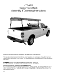
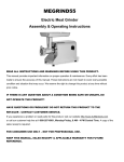
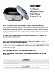
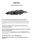
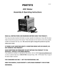
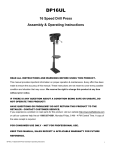
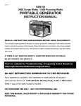
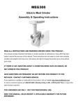
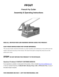
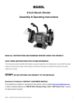
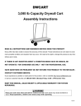
HTRACKC
Horizontal Truck Rack
Assembly & Operating Instructions
READ ALL INSTRUCTIONS AND WARNINGS BEFORE USING THIS PRODUCT.
This manual provides important information on proper operation and maintenance. Every effort has been
made to ensure the accuracy of this manual. We reserve the right to change this product at any time without
prior notice.
STOP! DO NOT RETURN THIS PRODUCT TO THE RETAILER.
Questions? Problems? CONTACT CUSTOMER SERVICE.
If you experience a problem or need parts for this product, visit our website http://www.buffalotools.com or
call our customer help line at 1-888-287-6981, Monday-Friday, 8 AM - 4 PM Central Time. A copy of the
sales receipt is required.
2010 01
Horizontal Truck Rack HTRACKC
Assembly and Operating Instructions
Lay out all parts according to assembly diagram 1 and 2, parts list, and hardware list, to verify you
have received all necessary pieces.
ASSEMBLY DIAGRAM 1
A
B
B
3
10
12
2
1
C
D
5R
3
11
4R
F
5L
E
7
2
H
4L
7
6
14
6
F
14
14
2
G
13
14
HTRACKC Horizontal Truck Rack
Parts List
Item No.
1
2
3
4L
4R
5L
5R
6
7
10
11
12
13
14
Description
Cab Hoop
Front Side Kit
Rear Side Kit
Left Front Upstand
Right Front Upstand
Left Rear Upstand
Right Rear Upstand
Mounting Foot
Mounting Foot
Front Bar
Center Bar
Rear Bar
Clamps
Riser * (for trucks with tall cabs)
Quantity
1
2
2
1
1
1
1
2
2
1
1
1
4
4
Remarks
With Welded Tip
* Riser sold separately. Call Customer Service to order. Available free, just pay shipping/handling.
Hardware List
Item No.
Description
Quantity
Item No.
Description
Quantity
A
Bolt: M16 x 30
Nut: M16
Flat Washer: Φ16
4
4
8
F
B
Bolt: M12 x 50
Nut : M12
Flat Washer: Φ 12
8
8
8
G
C
Bolt: M12x50
2
H
D
Bolt : M10x35
Nut : M10
Flat Washer: Φ10
2
2
2
8
8
8
16
8
8
8
8
2
2
22
I
E
M12x75
Nut : M12
Flat Washer: Φ12
2
Bolt : M18x88
Nut : M18
Spring Washer: Φ18
Flat Washer: Φ18
Bolt: M12x72
Nut : M12
Spring Washer: Φ12
Flat Washer: Φ 12
Bolt : M10x70
Nut : M10
Spring Washer
Flat Washer: Φ10
“J” Shape Screw
Nut : M12
Spring Washer: Φ12
Flat Washer: Φ12
HTRACKC Horizontal Truck Rack
8
8
8
8
2
3
In order to properly assemble the rack you need to determine if the rack will be
installed on a LONG BED or SHORT BED truck.
WARNING: DO NOT tighten any bolts during the following steps.
Step 1
Slide one of the Rear Upstands (5) into the Rear Side Kit (3) as shown in Fig 2. Then connect them
using bolts, flat washers, and nuts provided.(B)
Step 2
Install the Rear Bar (12) over the end of the Side Kit as shown in Fig 3. Using bolt, (C) to attach the
Rear Bar to the Side Kit. Fig 4.
12
B
C
D
3
5
FIG 2
FIG 3
G
FIG 4
Step 3
Install 2 piece bolts (G) through the Rear Upstand (5) and the Rear Bar (12). Attach using flat and
spring washers, nuts as shown in Fig 4. Repeat the above steps to the opposite side.
Do not tighten any bolts.
WARNING: Truck bed size determines rack assembly. Follow instructions below.
Step 4
(For Short Bed Truck)
Slide the Front Bar (10) onto the Front Side Kit (2) first, then slide the Front Upstand (4) into Front
Side Kit backward as shown in Fig 6.
(For Long Bed Truck)
Slide the Front Bar (10) onto the Front Side Kit (2) first, then slide the Front Upstand into Front Side
Kit forward as shown in Fig 7 and Fig 8. Bolt the Front Upstand (4) using 2 piece bolt, flat washer,
and nut (B). Then connect the Front Upstand to the Front Bar (10) by 2 piece bolts (G), flat and
spring washers, nuts (G). Repeat to the opposite side.
Do not tight any bolts.
4
HTRACKC Horizontal Truck Rack
Backward
Forward
2
10
2
4
FIG 5
FIG 6
10
4
FIG 7
2
FIG 8
Step 5
Slide the Front and Rear Side Kit (2 & 3) together. Bolt the clamps together using 2 piece bolts (A)
with flat washers, nuts (A). Use Fig 9 and Fig 10 for reference. Repeat for the opposite side.
3
2
13
FIG 9
A
FIG 10
Step 6
Insert the Cab Hoop (1) into both Front Side Kits (2). Attach it to the Front Side Kits using 2 piece
bolts, flat washers, nuts (H). Use Fig 11 and Fig 12 for reference.
Remember do not tighten any bolts.
HTRACKC Horizontal Truck Rack
5
1
2
H
FIG 11
FIG 12
Step 7
Position the Center Bar (11) onto the Front or Rear Side Kits, and attach with 2 piece bolts, flat
washers, nuts (E). Fig 13. and Fig 14.
Note: The center bar is adjustable and can be placed anywhere along the length
of the Side Kit.
11
FIG 13
FIG 14
E
Step 8
Install the Left Front Mounting Foot (6) to the Bottom of the Front Upstand. Bolt them together using
2 piece bolts, 4 piece flat washers, 2 piece spring washers, and nuts. Fig 15 and Fig 16.
Note: All of the lips of the Mounting Feet must face towards the inside of the
truck bed.
Repeat above step to the other three mounting feet. Remember do not tighten any bolts.
4L
Flat washer
Flat washer
6
Spring washer
FIG 15
6
FIG 16
HTRACKC Horizontal Truck Rack
Step 9
You will need to know the distance between the Front Mounting Foot and the Rear Mounting Foot
and the size of the bed of your truck before lifting the rack onto your vehicle. Measure the length of
your truck with the tailgate closed, and measure between the center of the Front and Rear Upstands,
and move the Front Upstand backwards or forwards as needed to match the size of the truck bed.
Do not tighten any bolts.
Note: You will require assistance for the following steps.
Step 10
Position the Front Mounting Feet as close as possible to the front corner of the bed rails. Align the
Rear Mounting Feet as close as possible to the corner of the bed rail in order to position the rack onto
your vehicle more stability.
WARNING: The Upstands can be adjusted while the rack is on the bed.
There are two ways to attach the Rack to your vehicle: No Drill Installation and Permanent Installation.
Please fellow the instructions below:
NO DRILL INSTALLATION
Step 11
You must use 2 "J" hooks (provided) per mounting foot order to attach the rack to your truck bed.
If there are obstructions under the bed rail which will prevent using the "J" hooks, move the Upstands
to the proper position.
Step 12
Insert the "J" hooks into the Mounting Foot as shown in Fig 17. Attach them using flat and spring
washers, nuts.
NOTE: If the threaded part of the "J" hook remaining above the bed rail is too long, cut it off with
a hacksaw.
Repeat the above steps to other three Mounting Feet.
7
I
FIG 17
HTRACKC Horizontal Truck Rack
7
PERMANENT INSTALLATION:
Step 11
Push the Mounting Foot towards the bed rail and make sure the lip of the Mounting Foot stays firmly
against the edge of the bed. Mark three slots on the top of the Mounting Foot using a felt tip marker.
Use Fig 18 and Fig 19 are for reference.
WARNING: Before drilling your vehicle's bed rails, you MUST check to see if you
have a clear hole from the top of rail to the underside of the rail. Use at least TWO
bolts to attach each Mounting Foot to the vehicle.
Step 12
Use a center punch to position the center of the holes, then drill the mounting holes in the bed rails
using a 5/16 drill bit.
FIG 18
FIG 19
Step 13
Bolt the rack to the bed rail using 2 piece bolts, 4 piece flat washers, 2 piece spring washers, and
2 piece nuts. Repeat the above steps to other three Mounting Feet.
Step 14
Stand in front of your truck and check if the Cap Hoop is parallel with the horizontal surface of the
truck cab roof. Push or pull the rack to adjust.
Step 15
When you are satisfied with the above steps, tighten the Mounting Feet first then tighten all other
bolts and screws.
Note:
Use Riser Kit only if extra height is needed to clear truck cab.
Part No. 4L, 4R, 5L, 5R - Upstand
Part No. 14 - Riser
Part No. 6 & 7 - Mounting Foot
8
HTRACKC Horizontal Truck Rack
HTRACKC
Support de caisse horizontal
Assemblage et mode d'emploi
CONSIGNES DE SÉCURITÉ
Veuillez lire toutes les instructions et mises en garde avant d'utiliser cet article.
ARRÊT! NE RENVOYEZ PAS CE GÉNÉRATEUR AU DÉTAILLANT.
Questions ? Problèmes ? OUTILS DE BUFFALO DE CONTACT. si vous éprouvez
un problème ou avez besoin des pièces pour ce produit, visitez notre site Web
http://www.buffalotools.com. Ou, appelez notre
ligne d'aide de client à 1-800-568-6657, Lundi-Vendredi, 8 AM - temps central 16 h.
Une copie du reçu de
ventes est exigée.
VEUILLEZ LIRE TOUTES LES INSTRUCTIONS ET MISES EN GARDE AVANT D'UTILISER CET ARTICLE.
Ce guide fournit des renseignements importants sur l'utilisation et l'entretien de cet article. Toutes les
mesures ont été prises afin d'assurer l'exactitude des informations. Nous nous réservons le droit de modifier
ce produit en tout temps sans préavis.
Attention!
NE RETOURNEZ PAS CE PRODUIT CHEZ LE DÉTAILLANT.
Questions ? Problèmes ? COMMUNIQUEZ AVEC BUFFALO TOOLS .
Si vous éprouvez des difficultés ou avez besoin de pièces pour ce produit, visitez notre site Web
http://www.buffalotools.com. ou appelez notre ligne d'aide à la clientèle au 1 888-287-6981, du lundi au
vendredi, de 8 h à 16 h HNC. Une copie du reçu de vente est exigée.
2010 01
Support de caisse horizontal HTRACKC Assemblage et mode d’emploi
En suivant les schémas d'assemblage numéro 1 et 2, les listes des pièces et de quincaillerie,
disposer toutes les pièces sur le sol et s'assurer qu'il n'en manque aucune.
Schéma d'assemblage n° 1
A
B
B
3
10
12
2
1
C
D
5R
3
11
G
13
4R
F
5L
E
7
2
H
4L
7
6
6
F
Schéma d'assemblage n° 2
14
14
14
2
14
HTRACKC Support de caisse horizontal
Liste des pièces
N° d'article
1
2
3
4L
4R
5L
5R
6
7
10
11
12
13
Description
Arceau de cabine
Monture côté - avant
Monture côté - arrière
Montant avant - gauche
Montant avant - droite
Montant arrière - gauche
Montant arrière - droite
Pied de montage - gauche
Pied de montage - droite
Traverse avant
Traverse centrale
Traverse arrière
Brides de fixation
Quantité
1
2
2
1
1
1
1
2
2
1
1
1
4
14
Rallonge **
4
Commentaire
Pointe soudée
Pour l'usage sur des camions à
grandes cabines.
Rallonge ** vendu séparément. COMMUNIQUEZ AVEC BUFFALO TOOLS 1-888-287-6981
Liste de quincaillerie
N°
d'article
A
B
Description
Quantité
Description
Quantité
Boulon : M16 x 30
N°
d'article
4
F
Boulon :M18x88
8
Écrou : M16
Rondelle plate : Ø 16
4
Écrou :M18
Rondelle à ressort:
Ø 18
Rondelle plate :
φ18
Boulon :M12x72
Écrou :M12
Rondelle à
ressort : φ12
Rondelle plate φ12
Boulon :M10x70
Écrou :M10
Rondelle à ressort
Rondelle plate φ10
Crochet en J
Écrou :M12
Rondelle à ressort
φ12
Rondelle plate φ12
8
Boulon : M12 x 50
Écrou :M12
8
8
8
G
Rondelle plate φ12
C
Boulon : M12x50
8
2
D
Boulon :M10x35
Écrou :M10
Rondelle plate φ10
2
2
2
E
M12x75
2
Écrou :M12
Rondelle plate φ12
2
HTRACKC Support De Caisse Horizontal
H
I
8
16
8
8
8
8
2
2
22
8
8
8
8
3
Afin d'assembler correctement le support de caisse, il faut déterminer s'il sera
installé sur un camion à plate-forme LONGUE ou COURTE. ATTENTION : NE
serrer AUCUN boulon pendant les étapes suivantes.
ÉTAPE 1
Faire glisser un montant arrière (5) dans la monture de côté arrière (3), tel qu'illustré à la figure 2.
Puis fixer le tout à l'aide des boulons, rondelles plates et écrous fournis (B).
ÉTAPE 2
Installer la traverse arrière (12) à l'extrémité de la monture de côté, tel qu'illustré à la figure 3. À
l'aide d'un boulon (C), fixer la traverse arrière à la monture de côté (figure 4).
12
B
C
D
3
5
FIG 2
FIG 3
G
FIG 4
ÉTAPE 3
Installer deux boulons (G) dans le montant arrière (5) et la traverse arrière (12). Fixer à l'aide des
rondelles plates et à ressort et des écrous, tel qu'illustré à la figure 4. Répéter les étapes ci-dessus pour
assembler l'autre côté. NE SERRER AUCUN BOULON MAINTENANT.
ATTENTION : SUIVRE LES INSTRUCTIONS CI-DESSOUS SELON LA PLATE-FORME
DE CAMION UTILISÉE.
ÉTAPE 4
(Camion à plate-forme COURTE)
Faire d'abord glisser la traverse avant (10) dans la monture côté avant (2), puis faire glisser le montant
avant gauche (4) à l'arrière dans la monture côté avant, tel qu'illustré à la figure 6.
(Camion à plate-forme LONGUE)
Faire glisser la traverse avant (10) dans la monture côté avant (2) en premier, puis faire glisser le
montant avant dans la monture côté avant, tel qu'illustré à la figure 7 et 8. Fixer le montant avant (4) à
l'aide de deux boulons, deux rondelles plates et deux écrous (B). Puis, fixer le montant avant à la
traverse avant (10) à l'aide de deux boulons (G), deux rondelles plates et à ressort et deux écrous (G).
Répéter cette étape pour assembler l'autre côté. NE SERRER AUCUN BOULON MAINTENANT.
4
HTRACKC Supprt de caisse horizontal
Avant
Backward
Arrière
Forward
Pour les plate-formes
longues, faire glisser
les éléments de ce
côté.
2
2
Pour les plate-formes
courtes, faire glisser
les éléments de ce
côté.
10
4
FIG 5
FIG 6
10
4
FIG 7
2
FIG 8
ÉTAPE 5
Insérer les montures avant et arrière (2 et 3) l'une dans l'autre. Serrer les brides de fixation à l'aide de
deux boulons (A), deux rondelles plates et deux écrous (A) selon les figures 9 et 10. Répéter cette étape
pour assembler l'autre côté.
3
2
13
FIG 9
A
FIG 10
ÉTAPE 6
Insérer l'arceau de cabine (1) dans les deux montures avant (2) et le fixer à l'aide de deux boulons, deux
rondelles plates et deux écrous (H) selon les figures 11 et 12. Ne serrer aucun boulon maintenant.
HTRACKC Support de caisse horizontal
5
1
2
H
FIG 11
FIG 12
ÉTAPE 7
Poser la traverse centrale (11) sur les montures avant et arrière et la fixer à l'aide de deux boulons,
deux rondelles plates et deux écrous (E) selon les figures 13 et 14.
NOTE : La traverse centrale est réglable et peut être fixée n'importe où sur la
longueur de la monture de côté.
11
FIG 13
FIG 14
E
ÉTAPE 8
Poser le pied de montage avant gauche (6) à la base du montant avant et les fixer ensemble à l'aide
de deux boulons, quatre rondelles plates, deux rondelles à ressort et deux écrous selon les figures
15 et 16.
Note : Toutes les lèvres des pieds de montage doivent faire face à l'intérieur de
la plate-forme du camion.
4L
Rondelle plate
6
Rondelle plate
Rondelle à
ressort
FIG 15
FIG 16
Répéter cette étape pour installer les trois autres pieds de montage. Ne serrer aucun
boulon maintenant.
6
HTRACKC Support de caisse horizontal
ÉTAPE 9
Déterminer la distance entre le pied de montage avant et arrière et la dimension de la plate-forme du
camion avant de poser le support sur le véhicule. Mesurer la longueur de la plate-forme avec la porte
fermée et mesurer entre le centre des montants avant et arrière. Déplacer les montants avant vers
l'avant ou l'arrière au besoin afin d'obtenir la bonne dimension de la plate-forme.
Ne serrer aucun boulon maintenant. Effectuer les étapes suivantes avec l'aide
d'une ou deux personnes afin de soulever et déposer le support sur la plate-forme
du camion.
ÉTAPE 10
Placer les pieds de montage avant aussi près que possible du coin avant des rails de plate-forme.
Aligner les pieds de montage arrière aussi près que possible du coin des rails de plate-forme de
manière à assurer plus de stabilité au support sur le véhicule.
ATTENTION : Les montants peuvent être ajustés alors que le support est posé
sur la plate-forme.
Le support peut être fixé au véhicule de deux façons : sans percer de trous ou installation
permanente. Veuillez suivre les étapes ci-dessous.
INSTALLATION SANS PERCER DE TROUS
ÉTAPE 11
Utiliser deux crochets en J (fournis) par pied de montage pour tenir le support afin de le fixer à la
plate-forme du véhicule. Si les rails de la plate-forme présentent des obstructions empêchant
l'utilisation des crochets en J, déplacer les montants à l'endroit approprié.
ÉTAPE 12
Insérer le crochet en J dans le pied de montage, tel qu'illustré à la figure 17 et les fixer à l'aide de
rondelles plates et à ressort et d'écrous.
NOTE : Si la partie filetée du crochet en J est trop longue au-dessus du rail de la plate-forme,
la couper avec une scie à métaux.
Répéter les étapes ci-dessus pour installer les trois autres pieds de montage.
7
I
FIG 17
HTRACKC Support de caisse horizontal
7
INSTALLATION PERMANENTE
ÉTAPE 11
Pousser le pied de montage vers le rail de la plate-forme et s'assurer que la lèvre du pied de montage
repose fermement contre le bord de la plate-forme. Marquer trois fentes sur le dessus du pied de
montage à l'aide d'un crayon feutre, tel qu'illustré à la figure 18 et 19.
ATTENTION: Avant de percer les rails sur la plate-forme du véhicule, il FAUT vérifier que le trou
passe de bord en bord du rail. Fixer chaque pied de montage au véhicule à l'aide d'au moins
DEUX boulons.
ÉTAPE 12
Utiliser un pointeau pour positionner le centre des trous, puis percer les trous de montage dans les
rails de la plate-forme à l'aide d'un foret de 5/16.
FIG 18
FIG 19
ÉTAPE 13
Fixer le support au rail de la plate-forme à l'aide de deux boulons, quatre rondelles plates, deux
rondelles à ressort et deux écrous.Répéter les étapes ci-dessus pour installer les trois autres pieds
de montage.
ÉTAPE 14
Debout devant le camion, vérifier si l'arceau est parallèle avec la surface horizontale du toit de la
cabine du camion. Si ce n'est pas le cas, demander à un aide de tirer ou de pousser le support afin
de faire l'ajustement.
ÉTAPE 15
Lorsque tous les ajustements sont terminés, bien serrer les boulons des pieds de montage en premier,
puis tous les autres boulons et vis.
NOTE: Utiliser la trousse de rallonge uniquement pour obtenir un dégagement suffisant entre
le support et la cabine du camion.
Part No. 4L, 4R, 5L, 5R - Montant
Part No. 14 - Rallonge
Part No. 6 & 7 - Pied de montage
8
HTRACKC Support de caisse horizontal