1
REV 001
nautical equipment evolution
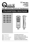
PULSANTIERA MULTIUSO
HRC 1002
HRC 1004
HRC 1006
HRC 1008
HRC 1002 L
HRC 1004 L
HRC 1006 L
HRC 1008 L
UP
DOWN
LEFT
RIGHT
I
Manuale d’uso
PULSANTIERA MULTIUSO HRC
GB
User’s Manual
HRC MULTIPURPOSE CONTROL PANEL
F
Manuel de l’utilisateur
BOITIER DE COMMANDE MULTI-USAGE HRC
D
Benutzerhandbuch
MEHRZWECK-FERNBEDIENUNG HRC
E
Manual del usuario
TABLERO DE PULSADORES MULTIUSO HRC
I
INDICE
Pag. 4 Caratteristiche e Installazione installazione della presa
Pag. 5 Installazione installazione della presa
Pag. 6 Funzionamento - connessione della
pulsantiera alla presa
GB
INDEX
Pg. 10 Characteristics and installation installing the socket
Pg. 11 Installation - installing the socket
Pg. 12 Operating - connecting the control
panel to the socket
F
P. 19 Fonctionnement schémas de branchement
P. 20 Fonctionnement - allumage et
extinction de la torche
P. 21 Caractéristiques techniques
INHALTSANGABE
S. 22 Eigenschaften und Installation
Installation der Steckdose
S. 23 Installation - Installation der Steckdose
S. 24 Betrieb - Anschluss der
Fernbedienung an die Steckdose
E
Pg. 13 Operating - connection diagrams
Pg. 14 Operating switching the torch on and off
Pg. 15 Technical data
SOMMAIRE
P. 16 Caractéristiques et installation installation de la prise
P. 17 Installation - installation de la prise
P. 18 Fonctionnement - connexion du
boîtier de commande à la prise
D
Pag. 7 Funzionamento schemi di collegamento
Pag. 8 Funzionamento - accensione e
spegnimento della torcia
Pag. 9 Caratteristiche tecniche
S. 25 Betrieb - Anschlusstafeln
S. 26 Betrieb - Anschluss und Ausschalten
der Lampe
S. 27 Technische daten
INDICE
Pág. 28 Características e Instalación instalación de la toma
Pág. 29 Instalación - instalación de la toma
Pág. 30 Funcionamiento - conexión del
tablero de pulsadores en la toma
Pág. 31 Funcionamiento - esquema de
conexión
Pág. 32 Funcionamiento - prender y apagar
la antorcha
Pág. 33 Caracteristicas tecnicas
3
I
CARATTERISTICHE E INSTALLAZIONE
PULSANTIERA MULTIUSO
La pulsantiera multiuso Quick™ è uno strumento progettato per azionare a distanza vari
sistemi mobili a bordo dell’imbarcazione come gruette, passerelle, scalette-bagno, salpa
ancora.
INSTALLAZIONE
PRIMA DI UTILIZZARE LO STRUMENTO, LEGGERE ATTENTAMENTE IL PRESENTE
MANUALE D’USO. IN CASO DI DUBBI CONTATTARE IL RIVENDITORE O IL SERVIZIO
CLIENTI QUICK™.
La pulsantiera è stata progettata per gli scopi descritti in questo manuale d’uso. La società
Quick™ non si assume alcuna responsabilità per danni diretti o indiretti causati da un uso
improprio dell’apparecchio, da un’errata installazione o da possibili errori presenti in questo
manuale.
ATTENZIONE: l'utilizzatore elettrico, comandato dalla pulsantiera, deve essere dotato di
sistemi di sicurezza tali da impedire danni a persone, cose o all'ambiente che possano
generarsi da un difetto di funzionamento della pulsantiera.
L’APERTURA DELLO STRUMENTO DA PARTE DI PERSONALE NON AUTORIZZATO FA
DECADERE LA GARANZIA.
LA CONFEZIONE CONTIENE: pulsantiera, supporto, presa, guarnizione e coperchio presa, viti,
dima di foratura, il presente manuale d’uso.
INSTALLAZIONE DELLA PRESA
Di seguito sarà descritta una procedura di installazione tipica.
Non è possibile descrivere una procedura che sia applicabile a tutte le situazioni.
Adattare questa procedura per soddisfare i propri requisiti.
Individuare la posizione più adatta dove praticare la sede per alloggiare la presa seguendo
questi criteri:
• La presa deve essere posizionata in modo che sia facilmente raggiungibile dall’operatore.
• Scegliere una posizione che sia pulita, liscia e piana.
• Deve essere presente un accesso posteriore per l’installazione e la manutenzione.
• Deve esistere spazio sufficiente dietro alla posizione scelta per il libero passaggio del cavo
della presa.
• La parte posteriore della presa deve essere protetta dal contatto con acqua o umidità.
• Porre particolare attenzione quando si effettuano i fori sui pannelli o su parti dell’imbarcazione.
Questi fori non devono indebolire o causare rotture alla struttura dell’imbarcazione.
4
INSTALLAZIONE
I
Installazione della presa
Dopo aver scelto dove posizionare lo strumento, procedere come riportato di seguito:
• Posizionare la dima di foratura (fornita in dotazione) sulla superficie dove sarà installata la presa.
• Marcare il centro di ogni foro.
• Realizzare il foro per il passaggio del cavo della presa con una fresa diametro indicato sulla
dima di foratura.
• Rimuovere la dima ed eventuali bave presenti sul foro.
• Applicare la guarnizione alla base della presa.
• Inserire il cavo nel foro praticato.
• Fissare la presa avvitando le 4 viti in dotazione.
• Prima di procedere con i collegamenti elettrici accertarsi che l’alimentazione non sia presente.
• Per il collegamento elettrico dei cavi, riferirsi alla colorazione dei cavi in fig. 1.
• Inserire un fusibile rapido da 200mA sulla linea di alimentazione della torcia (cavi A e B, se presenti).
• Alimentare la pulsantiera solo dopo aver effettuato e verificato l’esattezza di tutti i collegamenti
elettrici.
HRC 1002
HRC 1004
UP
DOWN
LEFT
RIGHT
HRC 1006
HRC 1008
HRC 1002 L
HRC 1004 L
HRC 1006 L
HRC 1008 L
UP
DOWN
LEFT
RIGHT
5
I
FUNZIONAMENTO
CONNESSIONE DELLA PULSANTIERA ALLA PRESA
HRC 1002 - HRC 1004
Connessione dello strumento
Dopo avere installato la presa come descritto in precedenza, procedere come riportato di
seguito:
• Estrarre il coperchio di protezione della presa.
• Inserire la spina dello strumento nell’apposita presa facendo attenzione al verso d’inserzione.
• Ruotare la ghiera della spina in senso orario (innesto a baionetta) fino a serrarla
completamente.
Disconnessione dello strumento
• Ruotare la ghiera della spina in senso antiorario ed estrarla.
• Coprire la presa con l’apposito coperchio.
ATTENZIONE: assicurarsi di coprire la presa con l’apposito coperchio, quando lo
strumento è disconnesso.
CONNESSIONE DELLA PULSANTIERA ALLA PRESA
HRC 1006 - HRC 1008 - HRC 1002 L - HRC 1004 L - HRC 1006 L - HRC 1008 L
Connessione dello strumento
Dopo avere installato la presa come descritto in precedenza, procedere come riportato di
seguito:
• Ruotare la ghiera del coperchio di protezione in senso antiorario ed estrarla.
• Inserire la spina dello strumento nell’apposita presa facendo attenzione al verso d’inserzione.
• Ruotare la ghiera della spina in senso orario fino a serrarla completamente.
Disconnessione dello strumento
• Ruotare la ghiera della spina in senso antiorario fino a svitarla completamente ed estrarla.
• Coprire la presa con l’apposito coperchio, ruotando la ghiera in senso orario.
ATTENZIONE: assicurarsi di coprire la presa con l’apposito coperchio, quando lo
strumento è disconnesso.
6
FUNZIONAMENTO
I
FIG.1
HRC 1002
1
2
HRC 1004
2
1
2
1
2
3
4
3
4
3
4
5
6
5
6
7
8
MARRONE COMUNE
BLU
NERO
2
HRC 1008
1
MARRONE COMUNE
1
HRC 1006
MARRONE COMUNE
BLU
NERO
BIANCO
VERDE
1
2
3
4
MARRONE COMUNE
BLU
NERO
BIANCO
VERDE
ROSSO
GRIGIO
1
2
3
4
5
6
1
2
3
4
5
6
7
8
HRC 1002 L
1
2
HRC 1004 L
2
A
B
BLU
NERO
VIOLA
TURCHESE
HRC 1008 L
1
2
1
2
1
2
3
4
3
4
3
4
5
6
5
6
7
8
MARRONE COMUNE
1
HRC 1006 L
BLU
NERO
BIANCO
VERDE
ROSSO
GRIGIO
ARANCIO
GIALLO
MARRONE COMUNE
1
2
3
4
A
B
BLU
NERO
BIANCO
VERDE
VIOLA
TURCHESE
MARRONE COMUNE
1
2
3
4
5
6
A
B
BLU
NERO
BIANCO
VERDE
ROSSO
GRIGIO
VIOLA
TURCHESE
MARRONE COMUNE
1
2
3
4
5
6
7
8
A
A e B alimentazione torcia (senza polarità).
B
BLU
NERO
BIANCO
VERDE
ROSSO
GRIGIO
ARANCIO
GIALLO
VIOLA
TURCHESE
7
I
FUNZIONAMENTO
ACCENSIONE E SPEGNIMENTO DELLA TORCIA
HRC 1002 L / HRC 1008 L
L’accensione e lo spegnimento della torcia avviene premendo e rilasciando il pulsante che si
trova in alto con il simbolo della luce, vedere fig. 2.
All’accensione dello strumento la torcia è sempre spenta, anche se in precedenza lo strumento
è stato disconnesso dall’alimentazione con la torcia accesa.
FIG.2
UP
DOWN
LEFT
RIGHT
ATTENZIONE: nei modelli HRC 1002 / HRC 1008 è presente il tasto con il simbolo della
luce anche se non sono dotati della torcia.
8
CARATTERISTICHE TECNICHE
I
CARATTERISTICHE TECNICHE
HRC 1002
HRC 1002 L
MODELLO
HRC1004
HRC 1004 L
HRC 1006
HRC 1006 L
HRC 1008
HRC 1008 L
CARATTERISTICHE ELETTRICHE
Portata in corrente dei contatti (1)
5A
Tensione alimentazione torcia (2)
6 ÷ 30 Vdc
Assorbimento torcia (2)
100mA Max
CARATTERISTICHE AMBIENTALI
Temperatura operativa
Grado di protezione
(3)
-20 ÷ +70 °C
IP 67
CONTENITORE
Dimensioni (LxAxP)
62.2 x 185 x 49.4 mm
GENERALI
Massima estensione cavo
Classe EMC
(1)
(2)
(3)
4m
EN 55022/B
Su carico resistivo a 30 Vdc.
Solo nei modelli HRC 1002 L / HRC 1008 L.
Con la spina correttamente inserita nella presa. Esclusa la zona della presa dove è saldato il cavo di uscita (IP 00).
LA QUICK™ SI RISERVA IL DIRITTO DI APPORTARE MODIFICHE ALLE CARATTERISTICHE TECNICHE DELL’APPARECCHIO E AL CONTENUTO DI QUESTO MANUALE SENZA ALCUN PREAVVISO.
9
GB
CHARACTERISTICS AND INSTALLATION
MULTIPURPOSE CONTROL PANEL
The Quick™ multipurpose control panel is an instrument designed for the remote control of
various moving systems on board a boat, including mini-crane, gangplank, swimming ladder,
anchor hoist.
INSTALLATION
BEFORE USING THE INSTRUMENT STUDY THE PRESENT MANUAL OF USE. IN CASES OF
DOUBT CONTACT THE RETAILER OR QUICK™ CUSTOMER SERVICE.
The control was designed for the purposes described in this manual of use. The company
Quick™ does not accept any responsibility for direct or indirect damage caused by the
improper use of the device, by incorrect installation, or for any errors in the present manual.
WARNING: the electrical appliance controlled by the control panel must be provided
with safety systems to prevent damage to persons, things, or the environment that
might result from the defective operation of the control panel.
THE OPENING OF THE INSTRUMENT BY UNAUTHORIZED PERSONNEL MAKES THE
WARRANTY VOID.
THE PACKAGE CONTAINS: control panel, support, socket, socket seal and cover, screws,
drilling template, the present manual of use.
FITTING THE SOCKET
A typical installation procedure is described below.
It is not possible to define a single procedure that is applicable in every situation.
Adapt the procedure described here to your own requirements.
Identify the most appropriate position for the socket seating on the basis of the following
criteria:
• The socket must be positioned so that it can easily be reached by the operator.
• Choose a clean, smooth, flat location.
• Rear access is required for installation and maintenance.
• There must be sufficient space behind the chosen position for the passage of the socket
cable.
• The back of the socket must not be exposed to contact with water or humidity.
• Take particular attention when drilling the panels or parts of the boat. The holes must not
weaken or cause the breakage of structural elements of the boat.
10
INSTALLATION
GB
Installing the socket
After choosing where to position the instrument, proceed as follows:
• Position the drilling template (provided) on the surface where the socket will be installed.
• Mark the centre of each hole.
• Create the hole for the passage of the socket cable with a milling cutter of diameter indicated
on the drilling template.
• Remove the template and any splinters around the hole.
• Fit the seal to the socket base.
• Put the cable through the hole created.
• Fix the socket in position with the 4 screws provided.
• Before making the electrical connections ensure that the electrical supply is not connected.
• For the connection of the electrical wires refer to the wire colouring as in fig. 1.
• Insert a fast-acting fuse of 200mA on the torch supply line (wires A and B, if present).
• Before switching on the power to the control, check that all the electrical connections are
correct.
HRC 1002
HRC 1004
UP
DOWN
LEFT
RIGHT
HRC 1006
HRC 1008
HRC 1002 L
HRC 1004 L
HRC 1006 L
HRC 1008 L
UP
DOWN
LEFT
RIGHT
11
GB
OPERATING
CONNECTING THE CONTROL PANEL TO THE SOCKET
HRC 1002 - HRC 1004
Connecting the instrument
After installing the socket as described above, proceed as follows:
• Remove the protective cover from the socket.
• Insert the instrument plug in the socket, taking care that the position of insertion is correct.
• Rotate the plug locking ring-nut clockwise (bayonet connection) until fully closed.
Disconnecting the instrument
• Rotate the plug locking ring-nut anticlockwise and remove it.
• Cover the socket with the cover provided.
WARNING: always ensure that the socket is closed with the cover provided when the
instrument is disconnected.
CONNECTING THE CONTROL PANEL TO THE SOCKET
HRC 1006 - HRC 1008 - HRC 1002 L - HRC 1004 L - HRC 1006 L - HRC 1008 L
Connecting the instrument
After installing the socket as described above, proceed as follows:
• Rotate the ring-nut of the protective cover anticlockwise and remove it.
• Insert the instrument plug into the relevant socket, taking care that the position of insertion is
correct.
• Turn the plug locking ring-nut clockwise until fully closed.
Disconnecting the instrument
• Turn the plug locking ring-nut anticlockwise until fully open and remove.
• Cover the socket with the cover provided, turning the ring-nut clockwise.
WARNING: always ensure that the socket is closed with the cover provided when the
instrument is disconnected.
12
OPERATING
GB
FIG.1
HRC 1002
1
2
HRC 1004
2
1
2
1
2
3
4
3
4
3
4
5
6
5
6
7
8
BROWN ROUND
BLUE
BLACK
2
HRC 1008
1
BROWN ROUND
1
HRC 1006
BROWN ROUND
BLUE
BLACK
WHITE
GREEN
1
2
3
4
BROWN ROUND
BLUE
BLACK
WHITE
GREEN
RED
GREY
1
2
3
4
5
6
1
2
3
4
5
6
7
8
HRC 1002 L
1
2
HRC 1004 L
2
A
B
BLUE
BLACK
PURPLE
TURQUOISE
HRC 1008 L
1
2
1
2
1
2
3
4
3
4
3
4
5
6
5
6
7
8
BROWN ROUND
1
HRC 1006 L
BLUE
BLACK
WHITE
GREEN
RED
GREY
ORANGE
YELLOW
BROWN ROUND
1
2
3
4
A
B
BLUE
BLACK
WHITE
GREEN
PURPLE
TURQUOISE
BROWN ROUND
1
2
3
4
5
6
A
B
BLUE
BLACK
WHITE
GREEN
RED
GREY
PURPLE
TURQUOISE
BROWN ROUND
1
2
3
4
5
6
7
8
A
A and B torch supply (without polarity).
B
BLUE
BLACK
WHITE
GREEN
RED
GREY
ORANGE
YELLOW
PURPLE
TURQUOISE
13
GB
OPERATING
SWITCHING THE TORCH ON AND OFF
HRC 1002 L / HRC 1008 L
The torch is switched on and off by pressing and releasing the button at the top with the light
symbol, see fig. 2. When the instrument is first switched on the torch is always off, even if
previously disconnected from the supply with the torch on.
FIG.2
UP
DOWN
LEFT
RIGHT
WARNING: models HRC 1002 / HRC 1008 have the button with the light symbol even
though they are not equipped with a torch.
14
TECHNICAL DATA
GB
TECHNICAL DATA
HRC 1002
HRC 1002 L
MODEL
HRC1004
HRC 1004 L
HRC 1006
HRC 1006 L
HRC 1008
HRC 1008 L
ELECTRICAL CHARACTERISTICS
Current capacity of contacts (1)
5A
Torch supply voltage (2)
6 ÷ 30 Vdc
Torch power absorption (2)
100mA Max
AMBIENT CHARACTERISTICS
Operating temperature
Protection rating
(3)
-20 ÷ +70 °C
IP 67
CASE
Dimensions (LxHxD)
62.2 x 185 x 49.4 mm
GENERAL
Maximum cable extension
EMC class
(1)
(2)
(3)
4m
EN 55022/B
On resistive load at 30 Vdc.
Only on models HRC 1002 L / HRC 1008 L.
With the plug correctly inserted into the socket. Excluding the area of the socket where the exit cable is fixed (IP 00).
QUICK™ RESERVES THE RIGHT TO MODIFY THE TECHNICAL CHARACTERISTICS OF THE EQUIPMENT AND THE CONTENTS OF THIS MANUAL WITHOUT PRIOR NOTICE.
15
F
CARACTERISTIQUES ET INSTALLATION
BOITIER DE COMMANDE MULTI-USAGE
Le boîtier de commande Quick™ est un instrument conçu pour actionner à distance différents
systèmes mobiles à bord du bateau comme des grues, des passerelles, des échelles de bain,
des guindeaux.
INSTALLATION
AVANT D’UTILISER L’INSTRUMENT, LIRE ATTENTIVEMENT CE MODE D’EMPLOI.
EN CAS DE DOUTES, CONTACTER LE REVENDEUR OU LE SERVICE CLIENTELE
QUICK™.
Le boîtier de commande a été conçu pour les utilisations décrites dans ce mode d'emploi. La
firme Quick™ n’assume aucune responsabilité en cas de dommages directs ou indirects
causés par une utilisation impropre de l’appareil, par une mauvaise installation ou par des
erreurs éventuelles dans ce manuel.
ATTENTION: l’appareil électrique, commandé par le boîtier de commande, doit être
équipé de systèmes de sécurité visant à empêcher les dommages aux personnes, aux
biens ou à l’environnement, qui pourraient être dus à un défaut de fonctionnement du
boîtier de commande.
L’OUVERTURE DE L’INSTRUMENT PAR DU PERSONNEL NON AUTORISE REND
AUTOMATIQUEMENT LA GARANTIE NON VALIDE.
L’EMBALLAGE CONTIENT: le boîtier de commande, le support, la prise, la garniture et le
couvercle de la prise, les vis, le gabarit de perçage, le mode d’emploi.
INSTALLATION DE LA PRISE
La procédure d’installation typique est décrite ci-après.
Il n’est pas possible de fournir une procédure qui soit applicable à toutes les situations.
Adapter cette procédure pour répondre aux propres conditions requises.
Déterminer la position la plus adaptée où préparer l’emplacement de la prise en suivant ces
critères:
• La prise doit être placée de façon à être facilement accessible par l’opérateur.
• Choisir une position propre, lisse et plate.
• Il faut un accès par l'arrière pour l’installation et l’entretien.
• Il faut un espace suffisant derrière la position choisie pour le libre passage du câble de la
prise.
• La partie postérieure de la prise doit être protégée du contact avec l’eau ou l’humidité.
• Faire particulièrement attention quand on perce les trous sur les panneaux ou sur des pièces
du bateau.
• Ces trous ne doivent pas affaiblir ou causer de ruptures à la structure du bateau.
16
INSTALLATION
F
Installation de la prise
Après avoir choisi où placer l’instrument, procéder comme indiqué ci-après:
• Placer le gabarit de perçage (livré avec le produit) sur la surface où sera installée la prise.
• Marquer le centre de chaque trou.
• Faire le trou pour le passage du câble de la prise avec un forêt du diamètre indiqué sur le
gabarit de perçage.
• Retirer le gabarit et nettoyer les bavures éventuelles dans le trou.
• Appliquer la garniture à la base de la prise.
• Introduire le câble dans le trou préparé.
• Fixer la prise en vissant les 4 vis fournies.
• Avant d'effectuer les branchements électriques, vérifier qu'il n'y ait pas d'alimentation électrique
au moment du branchement.
• Pour le branchement électrique des câbles, se référer à la couleur des câbles sur la fig. 1.
• Mettre un fusible rapide de 200mA sur la ligne d’alimentation de la torche (câbles A et B, si
présents).
• Alimenter le boîtier uniquement après avoir effectué et vérifié l’exactitude de tous les
branchements électriques.
HRC 1002
HRC 1004
UP
DOWN
LEFT
RIGHT
HRC 1006
HRC 1008
HRC 1002 L
HRC 1004 L
HRC 1006 L
HRC 1008 L
UP
DOWN
LEFT
RIGHT
17
F
FONCTIONNEMENT
CONNEXION DU BOITIER DE COMMANDE A LA PRISE
HRC 1002 - HRC 1004
Connexion de l’instrument
Après avoir installé la prise selon la description ci-dessus, procéder comme suit:
• Enlever le couvercle de protection de la prise.
• Introduire la fiche de l’instrument dans la prise correspondante en faisant attention au sens
d’introduction.
• Tourner l’embout de la prise dans le sens des aiguilles d’une montre (branchement à
baïonnette) jusqu’à la serrer complètement.
Déconnexion de l’instrument
• Tourner l’embout de la fiche dans le sens contraire aux aiguilles d'une montre et le retirer.
• Couvrir la prise avec son couvercle.
ATTENTION: Assurez-vous de couvrir la prise avec le bon couvercle, lorsque
l’instrument est déconnecté.
CONNEXION DU BOITIER DE COMMANDE A LA PRISE
HRC 1006 - HRC 1008 - HRC 1002 L - HRC 1004 L - HRC 1006 L - HRC 1008 L
Connexion de l’instrument
Après avoir installé la prise selon la description fournie, procéder comme suit:
• Tourner l’embout du couvercle de protection dans le sens contraire aux aiguilles d’une
montre et l’extraire.
• Introduire la fiche de l’instrument dans la prise en faisant attention au sens d’insertion.
• Tourner l'embout de la fiche dans le sens des aiguilles d'une montre jusqu'à la serrer
complètement.
Déconnexion de l’instrument
• Tourner l’embout de la fiche dans le sens contraire aux aiguilles d’une montre jusqu’à la
dévisser complètement et l’extraire.
• Couvrir la prise avec le couvercle en tournant l'embout dans le sens des aiguilles d'une
montre.
ATTENTION: s'assurer de bien couvrir la prise avec son couvercle quand l'instrument
est déconnecté.
18
FONCTIONNEMENT
F
FIG.1
HRC 1002
1
2
HRC 1004
2
1
2
1
2
3
4
3
4
3
4
5
6
5
6
7
8
MARRON COMMUN
BLEU
NOIR
2
HRC 1008
1
MARRON COMMUN
1
HRC 1006
MARRON COMMUN
BLEU
NOIR
BLANC
VERT
1
2
3
4
MARRON COMMUN
BLEU
NOIR
BLANC
VERT
ROUGE
GRIS
1
2
3
4
5
6
1
2
3
4
5
6
7
8
HRC 1002 L
1
2
HRC 1004 L
2
A
B
BLEU
NOIR
MAUVE
BLEU TURQUOISE
HRC 1008 L
1
2
1
2
1
2
3
4
3
4
3
4
5
6
5
6
7
8
MARRON COMMUN
1
HRC 1006 L
BLEU
NOIR
BLANC
VERT
ROUGE
GRIS
ORANGE
JAUNE
MARRON COMMUN
1
2
3
4
A
B
BLEU
NOIR
BLANC
VERT
MAUVE
BLEU TURQUOISE
MARRON COMMUN
1
2
3
4
5
6
A
B
BLEU
NOIR
BLANC
VERT
ROUGE
GRIS
MAUVE
BLEU TURQUOISE
MARRON COMMUN
1
2
3
4
5
6
7
8
A
A et B alimentation torche (sans polarité).
B
BLEU
NOIR
BLANC
VERT
ROUGE
GRIS
ORANGE
JAUNE
MAUVE
BLEU TURQUOISE
19
F
FONCTIONNEMENT
ALLUMAGE ET EXTINCTION DE LA TORCHE
HRC 1002 L / HRC 1008 L
L’allumage et l’extinction de la torche s'effectue en appuyant et en relâchant le bouton qui se
trouve en haut avec le symbole de la lumière, voir fig. 2.
Lors de l’allumage de l’instrument, la torche est toujours éteinte, même si auparavant
l’instrument a été déconnecté lorsque la torche était allumée.
FIG.2
UP
DOWN
LEFT
RIGHT
ATTENTION: les modèles HRC 1002 / HRC 1008 sont pourvus du bouton ave le symbole
de la lumière même s'ils ne sont pas équipés de torche.
20
CARACTÉRISTIQUES TECHNIQUES
F
CARACTÉRISTIQUES TECHNIQUES
HRC 1002
HRC 1002 L
MODÈLE
HRC1004
HRC 1004 L
HRC 1006
HRC 1006 L
HRC 1008
HRC 1008 L
CARACTÉRISTIQUES ELECTRIQUES
Charge maxi des contacts (1)
5A
Tension alimentation torche (2)
6 ÷ 30 Vdc
Consommation torche (2)
100mA Max
CARACTERISTIQUES AMBIANTES
Température de service
Degré de protection
(3)
-20 ÷ +70 °C
IP 67
COFFRET
Dimensions (LxHxP)
62.2 x 185 x 49.4 mm
CARACTERISTIQUES GENERALES
Extension maximum du câble
Catégorie EMC
(1)
(2)
(3)
4m
EN 55022/B
Surcharge résistive sous 30 Vdc.
Uniquement sur les modèles HRC 1002 L / HRC 1008 L.
Avec la fiche correctement introduite dans la prise. La zone de la prise où est soudé le câble de sortie est exclue (IP 00).
LA QUICK™ SE RÉSERVE LE DROIT D’APPORTER DES MODIFICATIONS AUX CARACTÉRISTIQUES TECHNIQUES DE L’INSTRUMENT ET AU CONTENU DE CE MODE D’EMPLOI SANS AUCUN PRÉAVIS.
21
D
EIGENSCHAFTEN UND INSTALLATION
MULTIFUNKTIONALE FERNBEDIENUNG
Die Mehrzweck-Tastatur Quick™ ist eine Fernbedienung für verschiedene bewegliche Systeme
an Bord, wie Davits, Laufgänge, Badeleiter, Ankerkette.
INSTALLATION
BEVOR SIE IHR NEUES GERÄT IN BETRIEB NEHMEN, LESEN SIE BITTE DIE
GEBRAUCHSANWEISUNG SORGFÄLTIG DURCH. SOLLTEN SIE FRAGEN HABEN,
SETZEN SIE SICH BITTE MIT DER QUICK-VERTRETUNG IHRES LANDES IN
VERBINDUNG.
Diese Fernbedienung wurde für die in dieser Gebrauchsanweisung beschriebenen Zwecke
entwickelt. Die Firma Quick™ übernimmt keine Verantwortung für Schäden, die direkt oder
indirekt durch die unsachgemäße Benutzung des Gerätes, durch eine falsche Installation oder
mögliche Fehler in diesem Handbuch verursacht wurden.
ACHTUNG: Das elektrische Gerät, das mit der Fernbedienung bedient wird, muss mit
speziellen Sicherheitssystemen zur Verhinderung von Schäden an Personen, Sachen
oder der Umwelt ausgestattet sein; besagte Schäden könnten durch einen unsachgemäßen Betrieb der Fernbedienung entstehen.
DAS ÖFFNEN DES GERÄTES DURCH NICHT AUTORISIERTES PERSONAL HAT DEN VERFALL
DER GARANTIE ZUR FOLGE.
IM LIEFERUMFANG BEFINDEN SICH: Fernbedienung, Halterung, Steckdose, Dichtung und
Steckdosendeckel, Schrauben, gelochte Schablone und die vorliegende Gebrauchsanleitung.
INSTALLATION DER STECKDOSE
Im Folgenden wird ein typisches Installationsbeispiel beschrieben. Leider ist es nicht möglich,
Installationen für alle möglichen Situationen aufzuzeigen.
Passen Sie diese Prozedur an Ihre Bedürfnisse an.
Legen Sie die am besten geeignete Position für die Anbringung der Steckdose fest; befolgen Sie
dabei diese Kriterien:
• Die Steckdose muss so positioniert sein, dass sie der Anwender einfach erreichen kann.
• Die Position muss sauber, glatt und eben sein.
• Es muss ein rückseitiger Zugang für Installations- und Wartungsmaßnahmen vorhanden sein.
• Es muss hinter der gewählten Position genug Platz für ein bequemes Durchführen des
Steckdosenkabels vorhanden sein.
• Der Rückteil der Steckdose muss vor Wasser oder Feuchtigkeit geschützt sein.
• Seien Sie besonders vorsichtig, wenn Sie die Bohrungen am Schott oder an der Bootsstruktur
vornehmen. Diese Bohrungen dürfen die Struktur des Bootes nicht in Mitleidenschaft ziehen
oder Brüche verursachen.
22
INSTALLATION
D
Installation der Steckdose
Nachdem den Montageort festgelegt wurde, gehen Sie wie folgt vor:
• Die (mitgelieferte) gelochte Schablone auf die Oberfläche anlegen, wo die Steckdose installiert
werden soll.
• Die Mitte jeder Bohrung anzeichnen.
• Die Bohrung für den Durchlauf des Kabels der Steckdose mit einer Fräse ausführen, deren Durchmesser auf der gelochten Schablone angegeben ist.
• Die Schablone und eventuelle Grate an der Bohrung entfernen.
• Die Dichtungen an der Basis der Steckdose anbringen.
• Das Kabel in die Öffnung einführen.
• Die Steckdose mit den 4 mitgelieferten Schrauben befestigen.
• Bevor die elektrischen Anschlüsse vorgenommen werden, vergewissern Sie sich, dass kein
Strom anliegt.
• Für die elektrischen Anschlüsse der Kabel richten Sie sich nach den Farben der Kabel in Abb. 1.
• Führen Sie eine flinke Sicherung mit 200mA in die Versorgung der Scheinwerfer-Lampe ein (Kabel
A und B, wenn vorhanden).
• Schließen Sie die Fernbedienung erst an, wenn alle Stromanschlüsse vorgenommen und überprüft wurden.
HRC 1002
HRC 1004
UP
DOWN
LEFT
RIGHT
HRC 1006
HRC 1008
HRC 1002 L
HRC 1004 L
HRC 1006 L
HRC 1008 L
UP
DOWN
LEFT
RIGHT
23
D
BETRIEB
ANSCHLUSS DER FERNBEDIENUNG AN DIE STECKDOSE
HRC 1002 - HRC 1004
Anschluss des Gerätes
Nach Installation der Steckdose, wie oben beschrieben, gehen Sie nun wie folgt vor:
• Den Schutzdeckel der Steckdose entnehmen.
• Den Stecker des Gerätes in die Steckdose stecken; achten Sie dabei auf die Richtung, in die
der Stecker eingesetzt wird.
• Den Ring des Steckers im Uhrzeigersinn (Bajonettkupplung) drehen, bis er fest sitzt.
Abnehmen des Gerätes
• Den Ring des Steckers gegen den Uhrzeigersinn drehen und herausziehen.
• Die Steckdose mit dem entsprechenden Deckel verschließen.
ACHTUNG: Vergewissern Sie sich, dass die Steckdose mit dem passenden Deckel
verschlossen wird, wenn das Gerät nicht angeschlossen ist.
ANSCHLUSS DER FERNBEDIENUNG AN DIE STECKDOSE
HRC 1006 - HRC 1008 - HRC 1002 L - HRC 1004 L - HRC 1006 L - HRC 1008 L
Anschluss des Gerätes
Nach Installation der Steckdose, wie oben beschrieben, gehen Sie nun wie folgt vor:
• Den Ring des Schutzdeckels gegen den Uhrzeigersinn drehen und herausziehen.
• Den Stecker des Geräts in die entsprechende Steckdose stecken; achten Sie dabei auf die
Richtung, in die der Stecker eingesetzt wird .
• Den Ring des Steckers im Uhrzeigersinn drehen und ganz festdrehen.
Abnehmen des Gerätes
• Den Ring des Steckers gegen den Uhrzeigersinn drehen und komplett herausziehen.
• Die Steckdose mit dem entsprechenden Deckel verschließen; dazu den Ring im Uhrzeigersinn
drehen.
ACHTUNG: Vergewissern Sie sich, dass die Steckdose mit dem passenden Deckel
verschlossen wird, wenn das Gerät nicht angeschlossen ist.
24
BETRIEB
D
ABB.1
HRC 1002
1
2
HRC 1004
2
1
2
1
2
3
4
3
4
3
4
5
6
5
6
7
8
BRAUN GEMEINSAM
BLAU
SCHWARZ
2
HRC 1008
1
BRAUN GEMEINSAM
1
HRC 1006
BRAUN GEMEINSAM
BLAU
SCHWARZ
WEIß
GRÜN
1
2
3
4
BRAUN GEMEINSAM
BLAU
SCHWARZ
WEIß
GRÜN
ROT
GRAU
1
2
3
4
5
6
1
2
3
4
5
6
7
8
HRC 1002 L
1
2
HRC 1004 L
2
A
B
BLAU
SCHWARZ
LILA
TÜRKIS
HRC 1008 L
1
2
1
2
1
2
3
4
3
4
3
4
5
6
5
6
7
8
BRAUN GEMEINSAM
1
HRC 1006 L
BLAU
SCHWARZ
WEIß
GRÜN
ROT
GRAU
ORANGE
GELB
BRAUN GEMEINSAM
1
2
3
4
A
B
BLAU
SCHWARZ
WEIß
GRÜN
LILA
TÜRKIS
BRAUN GEMEINSAM
1
2
3
4
5
6
A
B
BLAU
SCHWARZ
WEIß
GRÜN
ROT
GRAU
LILA
TÜRKIS
BRAUN GEMEINSAM
1
2
3
4
5
6
7
8
A
A und B Einspeisung der Scheinwerfer-Lampe (ohne Polung).
B
BLAU
SCHWARZ
WEIß
GRÜN
ROT
GRAU
ORANGE
GELB
LILA
TÜRKIS
25
GERÄTEBETRIEB
D
EIN- UND AUSSCHALTEN DER SCHEINWERFER-LAMPE
HRC 1002 L / HRC 1008 L
Das Ein- und Ausschalten des Scheinwerfers geschieht durch Betätigen der Taste mit dem
Lichtsymbol oben, siehe Abb. 2.
Beim Einschalten des Gerätes ist der Scheinwerfer immer ausgeschaltet, auch wenn der
Scheinwerfer vorher bei Abschalten des Gerätes eingeschaltet war.
ABB.2
UP
DOWN
LEFT
RIGHT
ACHTUNG: Bei den Modellen HRC 1002 / HRC 1008 gibt es eine Taste mit dem
Lichtsymbol, obwohl diese nicht mit einem Scheinwerfer ausgestattet sind.
26
TECHNISCHE DATEN
D
TECHNISCHE DATEN
HRC 1002
HRC 1002 L
MODELL
HRC1004
HRC 1004 L
HRC 1006
HRC 1006 L
HRC 1008
HRC 1008 L
ELEKTRISCHE EIGENSCHAFTEN
Leistung der Kontakte in Strom (1)
5A
Speisungsspannung Lampe (2)
6 ÷ 30 Vdc
Absorption Lampe (2)
100mA Max
RAUMEIGENSCHAFTEN
Betriebstemperatur
Schutzstufe
(3)
-20 ÷ +70 °C
IP 67
BEHÄLTER
Abmessungen (LxBxT)
62.2 x 185 x 49.4 mm
ALLGEMEINES
Maximale Länge Kabel
EMC-Klasse
(1)
(2)
(3)
4m
EN 55022/B
Auf Widerstandslast 30 Vdc.
Nur bei den Modellen HRC 1002 L / HRC 1008 L.
Bei korrekt in die Steckdose eingestecktem Stecker. Mit Ausnahme des Steckdosenbereichs, wo das Ausgangskabel angelötet ist (IP 00).
QUICK™ BEHÄLT SICH DAS RECHT AUF ÄNDERUNGEN DER TECHNISCHEN EIGENSCHAFTEN DES GERÄTS UND DES INHALTS DIESES HANDBUCHS OHNE VORANKÜNDIGUNG VOR.
27
E
CARACTERÍSTICAS E INSTALACIÓN
TABLERO DE PULSADORES MULTIUSO
El tablero de pulsadores Quick™ es un instrumento proyectado para comandar de lejos varios
sistemas móviles a borde de la embarcación como las grúas, las pasarelas móviles, gradasbaño, molinetes.
INSTALACIÓN
PRIMERO DE UTILIZAR EL INSTRUMENTO, LEER CON ATENCIÓN EL PRESENTE
MANUAL DEL USUARIO. EN CASO DE DUDAS CONTACTAR EL REVENDEDOR O EL
SERVICIO DE CLIENTES QUICK™.
El tablero de pulsadores ha sido proyectado para las funciones descritas en este manual del
usuario. La sociedad Quick™ no se asume ninguna responsabilidad por daños directos o
indirectos causados por un uso impropio del aparato, por una equivocada instalación o por
posibles errores presentes en este manual.
ATENCIÓN: El usuario eléctrico, comandado del tablero de pulsadores, tiene que ser
dotado de sistemas de seguridad para poder impedir daños a las personas, a las cosas o
al ambiente que puedan generarse de un defecto de funcionamiento del tablero de
pulsadores.
LA ABERTURA DEL INSTRUMENTO POR PARTE DE PERSONAL NO AUTORIZADO HACE
DECAER LA GARANTíA.
LA CONFECCIÓN CONTIENE: tablero de pulsadores, soporte, toma, guarnición y tapa toma,
tornillos, plantilla, manual del usuario.
INSTALACIÓN DE LA TOMA
En seguida será descrito un procedimiento de instalación tìpico. No es posible describir un
procedimiento que se pueda aplicar a todas las situaciones. Adaptar éste procedimiento para
satisfacer los propios requisitos.
Escoger la posición más apta donde alojar la toma siguiendo estos criterios:
• La toma tiene que ser instalada en modo que sea fácilmente alcanzable para el usuario
• Escoger una posición que sea limpia, lisa y plana.
• Tiene que ser presente un acceso atrás del plano de donde se fija la toma, para la instalación
y la manutención.
• Tiene que haber espacio suficiente atrás de la posición escogida para el pasaje del cable de la
toma.
• La parte posterior de la toma tiene que ser protegida contra el contacto con el agua o humedad.
• Poner particular atención cuando se hacen los agujeros en los paneles o sobre partes de la
embarcación. Estos agujeros no tienen que debilitar o causar daños a la estructura de la
embarcación.
28
INSTALACIÓN
E
Instalación de la Toma
Después de haber escogido donde posicionar el instrumento, proceder como se muestra a continuación:
• Posicionar la plantilla (suministrada con el instrumento) sobre la superficie donde será instalado
el instrumento.
• Marcar el centro de cada agujero.
• Hacer los agujeros para el pasaje del cable de la toma con una fresa del diámetro indicado en
plantilla.
• Quitar la plantilla y eventuales babas presentes en los agujeros.
• Meter la guarnición en la base de la toma.
• Introducir el cable en el agujero hecho.
• Fijar la toma atornillando los 4 tornillos que son dotados con el instrumento.
• Primero de proceder con las conexiones eléctricas asegurarse que la alimentación non esté presente.
• Para las conexiones eléctricas de los cables, referirse a los colores de los cables en Fig. 1.
• Introducir un fusible rápido de 200mA en la linea de alimentación de la antorcha (cables A y B,
si son presentes).
• Alimentar el tablero de pulsadores solo después de haber verificado la exactitud de todas las
conexiones eléctricas.
HRC 1002
HRC 1004
UP
DOWN
LEFT
RIGHT
HRC 1006
HRC 1008
HRC 1002 L
HRC 1004 L
HRC 1006 L
HRC 1008 L
UP
DOWN
LEFT
RIGHT
29
E
FUNCIONAMIENTO
CONEXIÓN DEL TABLERO DE PULSADORES EN LA TOMA
HRC 1002 - HRC 1004
Conexión del instrumento
Después de haber instalado la toma como descrito primero, proseguir como se describe en
seguida:
• Quitar la tapa de protección de la toma.
• Introducir el enchufe del instrumento en su toma haciendo atención al sentido de
introducción.
• Hacer girar el anillo del enchufe en el sentido de las manecillas del reloj (injerto a bayoneta)
hasta bloquearla.
Desconexión del instrumento
• Hacer girar el anillo del enchufe en el sentido contrario de las manecillas del reloj y extraerlo.
• Cubrir la toma con su tapa.
ATENCIÓN: asegurarse de cubrir la toma con su tapa, cuando el instrumento está
desconectado.
CONEXIÓN DEL TABLERO DE PULSADORES EN LA TOMA
HRC 1006 – HRC 1008 – HRC 1002 L - 1004 L - 1006 L – HRC 1008 L
Conexión del instrumento
Después de haber instalado la toma como descrito primero, proseguir como se describe en
seguida:
• Hacer girar el anillo de la tapa de protección en el sentido contrario de las manecillas del reloj
y extraerla.
• Introducir el enchufe del instrumento en su toma haciendo atención al sentido de
introducción.
• Hacer girar el anillo del enchufe en el sentido de las manecillas del reloj hasta cerrarla
completamente.
Desconexión del instrumento
• Hacer girar el anillo del enchufe en el sentido contrario de las manecillas del reloj hasta
destornillarlo completamente y extraerlo.
• Cubrir la toma con su tapa, haciendo girar el anillo en el sentido de las manecillas del reloj.
ATENCIÓN: asegurarse de cubrir la toma con su tapa, cuando el instrumento está
desconectado.
30
FUNCIONAMIENTO
E
FIG.1
HRC 1002
1
2
HRC 1004
2
1
2
1
2
3
4
3
4
3
4
5
6
5
6
7
8
MARRÓN COMÚN
AZUL
NEGRO
2
HRC 1008
1
MARRÓN COMÚN
1
HRC 1006
MARRÓN COMÚN
AZUL
NEGRO
BLANCO
VERDE
1
2
3
4
MARRÓN COMÚN
AZUL
NEGRO
BLANCO
VERDE
ROJO
GRIS
1
2
3
4
5
6
1
2
3
4
5
6
7
8
HRC 1002 L
1
2
HRC 1004 L
2
A
B
AZUL
NEGRO
VIOLETA
TURQUESA
HRC 1008 L
1
2
1
2
1
2
3
4
3
4
3
4
5
6
5
6
7
8
MARRÓN COMÚN
1
HRC 1006 L
AZUL
NEGRO
BLANCO
VERDE
ROJO
GRIS
NARANJO
AMARILLO
MARRÓN COMÚN
1
2
3
4
A
B
AZUL
NEGRO
BLANCO
VERDE
VIOLETA
TURQUESA
MARRÓN COMÚN
1
2
3
4
5
6
A
B
AZUL
NEGRO
BLANCO
VERDE
ROJO
GRIS
VIOLETA
TURQUESA
MARRÓN COMÚN
1
2
3
4
5
6
7
8
A
A y B alimentación antorcha (sin polaridad).
B
AZUL
NEGRO
BLANCO
VERDE
ROJO
GRIS
NARANJO
AMARILLO
VIOLETA
TURQUESA
31
E
INSTALACIÓN
PRENDER Y APAGAR LA ANTORCHA
HRC 1002 L / HRC 1008 L
Para prender y apagar la antorcha se tiene que pulsar y dejar de pulsar el pulsador que está en
la parte superior con el símbolo de la luz, ver fig. 2.
Cuando se prende el instrumento la antorcha queda siempre apagada, aunque si primero el
instrumento se ha desconectado con la antorcha prendida.
FIG.2
UP
DOWN
LEFT
RIGHT
ATENCIÓN: En los modelos HRC 1002 / 1008 está presente el pulsador con el símbolo
de la luz aunque si no son dotados de la antorcha.
32
ESPECIFICACIONES TÉCNICAS
E
CARACTERÍSTICAS TÉCNICAS
HRC 1002
HRC 1002 L
MODELO
HRC1004
HRC 1004 L
HRC 1006
HRC 1006 L
HRC 1008
HRC 1008 L
CARACTERÍSTICAS ELÉCTRICAS
Máxima corriente de los contactos (1)
5A
Tensión de alimentación antorcha (2)
6 ÷ 30 Vdc
Absorción antorcha (2)
100mA Max
CARACTERÍSTICAS AMBIENTALES
Temperatura de trabajo
Grado de protección
(3)
-20 ÷ +70 °C
IP 67
CONTENEDOR
Medidas (LXAXP)
62.2 x 185 x 49.4 mm
GENERALES
Máxima extensión
Clase EMC
(1)
(2)
(3)
4m
EN 55022/B
Con carga resistiva a 30 Vdc.
Sólo modelos HRC 1002 L / HRC 1008 L.
Con el enchufe correctamente introducido el la toma. Excluida la zona de la toma donde está saldado el cable de salida (IP 00).
QUICK™ SE RESERVA EL DERECHO DE APORTAR MODIFICACIONES EN LAS CARACTERÍSTICAS TÉCNICAS DEL APARATO Y EN EL CONTENIDO DE ESTE MANUAL SIN OBLIGACIÓN DE AVISAR PREVIAMENTE.
33
HRC / L DIMENSIONI (mm)
DIMENSIONS - DIMENSIONS - ABMESSUNGEN - MEDIDAS
HRC 1002 / L
HRC 1004 / L
HRC 1006 / L
HRC 1008 / L
62.2
DOWN
LEFT
RIGHT
185
165
UP
59.1
34
49.4
41.6
NOTE
NOTES / NOTES / DIE ANMERKUNGEN / NOTAS
CMPLSHRC0R01
QUICK SRL - VIA PIANGIPANE , 120/A - 48020 PIANGIPANE (RAVENNA) - ITALY
TEL. +39.0544.415061 - FAX +39.0544.415047
www.quickitaly.com - E-mail: [email protected]