1
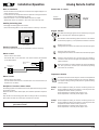
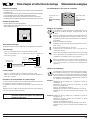
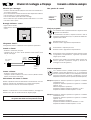
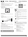
Montage- / Bedienungsanleitung
Montagehinweise
Analoge Fernbedienung
Gesamtansicht Bedienungsebene
- Montage der Fernbedienung (FB) an einer Innenwand in ca. 1.5 m Höhe
über Fußboden.
- Für die optimale Funktion des Raumtemperatursensors muß die FB in
einem repräsentativen Raum montiert werden.
- Die FB darf nicht von Schränken oder Vorhängen verdeckt werden.
- Alle Heizkörperventile müssen in diesem Raum voll geöffnet sein.
1
Linker Drehknopf
Temperaturwahl
2
3
4
0
1
2
3
_
4
+
Rechter Drehknopf
Programmwahl
Montage Wandsockel
- Wandsockel von der FB abnehmen.
- Wandsockel auf Unterputzdose Ø55mm anschrauben oder direkt an der
Wand befestigen.
Programmwahl
Mit dem rechten Drehknopf können fünf verschiedene
Heizprogramme ausgewählt werden. Im Einzelnen sind dies:
1
Im Automatikbetrieb arbeitet die Heizungsanlage nach dem
Schaltzeitenprogramm (1,2 od.3), das an der Kesselregelung
ausgewählt wurde.
4
Wandsockel
Heizbetrieb über 24 Stunden.
Speicherladung gemäß dem ausgewählten Schaltuhrenprogramm.
Elektrischer Anschluß
Die elektrische Verdrahtung darf nur von Fachkräften durchgeführt werden.
Sparbetrieb über 24 Stunden.
Speicherladung gemäß dem ausgewählten Schaltuhrenprogramm.
Fernbedienung
Sommerbetrieb (Heizung aus), Speicherladung gemäß ausgewähltem Schaltuhrenprogramm, Frostschutz für die Heizungsanlage gewährleistet.
- Betriebsschalter ausschalten
- FB mit 2-adrigem Kabel (Mindestquerschnitt 0,5mm²) entsprechend Skizze
verdrahten.
4
Brenner und Heizungsumwälzpumpe(n) aus, Speicherladung
aus, Frostschutz gewährleistet (siehe Montage-/Bedienungsanleitung Regelung).
Fernkontakt
bauseits
1
2
1
Bus
grün
Grüner Stecker
der Regelung
Temperaturwahl
Klemmleiste
Fernbedienung
1
2
3
Fernkontakt
4
- Betriebsschalter ausschalten
- Fernkontakt mit 2-adrigem Kabel (Mindestquerschnitt 0,5mm²) entsprechend Skizze verdrahten.
Funktionsbeschreibung Fernkontakt
Hier besteht die Möglichkeit direkt mit einem potentialfreien Kontakt die
Heizungsanlage auf 24 Stunden Heizbetrieb zu schalten.
Bleibt der Fernkontakt offen, läuft die Regelung im eingestellten Betrieb.
FB wieder auf Sockel aufsetzen und einrasten. Beim Aufsetzen darauf achten,
daß die Kontaktstifte an der FB nicht verbogen werden.
Achtung: Nach erfolgter Installation muß die Programmwahl der
Heizkesselregelung in Stellung AUTO gestellt werden.
0 1
2
3
_
4
+
Mit dem linken Drehknopf kann die aktuelle Raumtemperatur,
ausgehend von der Stellung 0, um +/- 4°C verändert werden.
Die Sollwertverstellung wirkt sich sowohl auf die eingestellte
Tagessolltemperatur (Heizbetrieb), als auch auf die eingestellte
Nachtsolltemperatur (Sparbetrieb) aus.
Beispiel 1: Eingestellte Raumtemperatur an der Regelung im
Heizbetrieb: 21°C
Eingestellte Raumtemperatur an der Regelung im
Sparbetrieb: 18°C
Temperaturwahl: Stellung 0
Raumtemperatur Heizbetrieb: ca. 21°C
Raumtemperatur Sparbetrieb: ca. 18°C
Beispiel 2: Eingestellte Raumtemperatur an der Regelung im
Heizbetrieb: 21°C
Eingestellte Raumtemperatur an der Regelung im
Sparbetrieb: 18°C
Temperaturwahl: Stellung 2
Raumtemperatur Heizbetrieb: ca. 23°C
Raumtemperatur Sparbetrieb: ca. 20°C
Wolf GmbH · Postfach 1380 · 84048 Mainburg · Tel. 08751/74-0 · Fax 08751/741600 · Internet: www.wolf-heiztechnik.de
Art.-Nr. 30 43 479
6.6701.311-00
04/05
D
Installation/Operation
Notes on installation
Analog Remote Control
General view of controls
- Mount the remote control (RC) on an interior wall at a height of approx. 1.5
meters above floor level .
- In order for the room-temperature sensor to operate correctly, the RC must
be installed where the temperature is typical.
- Make sure the RC is not concealed behind furniture or drapes.
- Thermostatic valves on radiators in this room must all be fully open.
1
2
3
Left knob
4
Temperature
0
1
2
3
_
4
+
Right knob
Program
Installing the backing plate
- Disengage the backing plate from the RC.
- Secure the backing plate to a dia. 55mm wall box or directly to the wall.
Program selection
Five different heating programs can be selected by turning the
knob on the right. The individual programs are:
1
In Automatic mode the heating system functions in accordance
with the timer program (1, 2 or 3) selected on the boiler controller.
4
Backing plate
Heating over 24 hours.
Storage tanks are heated in accordance with the timer program.
Electrical connection
Only trained, qualified electricians are permitted to connect the wiring.
Economy mode over 24 hours.
Storage tanks are heated in accordance with the timer program.
Remote control
- Switch off the main switch
- Wire the RC with 2-core cable (min. cross-section 0.5mm²) as illustrated
in the sketch below.
4
Summer mode (heating off), storage tanks are heated in
accordance with the timer program, frost protection for heating
system is ensured.
Rem.contact by
others
1
2
1
grün
Bus
Burner and heating circulation pump(s) off, storge-tank heating
off, frost protection ensured (see installation/operating
instructions for controller).
Green plug of
controller
Terminals,
RC
Temperature selection
Remote contact
- Switch off the main switch
- Wire the remote contact with 2-core cable (min. cross-section 0.5mm²) as
illustrated in the sketch.
Description of function: remote contact
The heating system can be switched to 24-hour operation directly, by means
of a floating contact.
While the remote contact remains open, the controller operates in the preset
mode.
1
0 1
2
3
4
2
3
_
4
+
The knob on the left is used to vary the current room temperature
+/- 4°C from the standard 0 setting. The correction applies to
the daytime setting (heating mode) and the nighttime setting
(economy mode).
Example
No. 1:
Room-temperature setting at controller in heating mode: 21°C
Room-temperature setting at controller in economy mode: 18°C
Temperature-selector knob: in position 0
Room temperature in heating mode: approx. 21°C
Room temperature in economy mode: approx. 18°C
Example
No. 2:
Room-temperature setting at controller in heating mode: 21°C
Room-temperature setting at controller in economy mode: 18°C
Temperature-selector knob: turned to position 2
Room temperature in heating mode: approx. 23°C
Room temperature in economy mode: approx. 20°C
Snap the RC onto the backing plate. When locating the RC on the backing
plate, make sure that the contact pins of the RC are not bent.
Important:
After installing, always set the boiler controller program selector to AUTO.
Wolf GmbH · Postfach 1380 · 84048 Mainburg · Tel. +49 8751/74-0 · Fax +49 8751/741600 · Internet: www.wolf-heiztechnik.de
GB
Mode d’emploi et instructions de montage
Télécommande analogique
Vue d’ensemble de la face avant de commande
Instructions de montage
- Montage de la télécommande (TC) sur un mur intérieur à environ 1,5m de hauteur
par rapport au sol.
- La télécommande doit être montée dans une pièce représentative afin de garantir
un fonctionnement optimal du capteur de température intérieure.
- La télécommande ne doit pas être couverte par une armoire ou des rideaux.
- Les robinets de tous les radiateurs situés dans la pièce doivent être ouverts à fond.
1
Commutateur rotatif
gauche
2
3
4
0
1
2
3
_
Commutateur rotatif
droit
4
+
Sélection de température
Montage du support mural
Sélection de programme
- Retirer le support mural de la télécommande.
- Visser le support mural directement dans le mur ou sur une boîte d’encastrement
(Ø 55mm) située dans le mur.
Sélection de programme
1
Le commutateur rotatif droit permet de sélectionner cinq programmes de chauffage différents. Ces programmes sont les
suivants:
En mode automatique, l’installation de chauffage fonctionne
selon l’un des programmes à commutation horaire (1,2 ou 3),
programme ayant été sélectionné auparavant sur la régulation
de chaudière.
Mode de chauffage sur 24 heures.
Chargement de l’accumulateur selon le programme de commutation horaire.
4
Support mural
Raccordement électrique
Le câblage électrique ne doit être effectué que par des personnes qualifiées.
Mode d’économie d’énergie sur 24 heures.
Chargement de l’accumulateur selon le programme de
commutation horaire.
Télécommande
- Placer le commutateur de fonctionnement en position d’arrêt.
- Câbler la télécommande avec un câble bifilaire (section minimale 0,5
mm²) selon le croquis.
4
Position «été» (chauffage à l’arrêt), chargement de l’accumulateur
selon le programme de commutation horaire. La protection de
l’installation de chauffage contre le gel est garantie.
Contact
éloigné
Brûleur et pompe(s) de circulation arrêtés. Chargement de
l’accumulateur hors service, protection contre le gel garantie
(voir le mode d’emploi et les instructions de montage de la
régulation).
1
2
1
Bus
grün
Connecteur vers la
régulation (vert)
Bornier de la
télécommande
Sélection de température
Contact éloigné
1
- Placer le commutateur de fonctionnement en position d’arrêt
- Câbler le contact éloigné avec un câble bifilaire (section minimale 0,5
mm²) selon le croquis.
0 1
2
3
4
2
3
_
4
+
Description du fonctionnement du contact éloigné
Un contact à potentiel flottant offre la possibilité de commuter l’installation
de chauffage en mode de chauffage sur 24 heures.
La régulation fonctionne suivant le mode sélectionné lorsque ce contact est
ouvert.
Replacer la TC sur le support et l’enclipser. Faire attention lors de l’opération
à ne pas tordre ses contacts électriques.
ATTENTION: après l’installation correcte, il est nécessaire de placer le
commutateur de sélection de programme de la régulation de
chaudière en position AUTO.
RSW
·
Parc Galvani
·
4, rue Galvani
·
Le commutateur rotatif gauche permet de faire varier la température actuelle de la pièce de +/- 4°C en considérant la position
0 comme référence. La variation de la température de consigne
affecte non seulement la température de consigne de jour (mode
de chauffage), mais également la température de consigne de
nuit (mode d’économie d’énergie).
Exemple 1: Température de pièce ajustée sur la régulation en mode de
chauffage: 21°C
Température de pièce ajustée sur la régulation en mode
d’économie d’énergie: 18°C
Sélection de température: position 0
Température de la pièce en mode de chauffage: 21°C environ
Température de la pièce en mode d’économie d’énergie: 18°C
environ
Exemple 2: Température de pièce ajustée sur la régulation en mode de
chauffage: 21°C
Température de pièce ajustée sur la régulation en mode
d’économie d’énergie: 18°C
Sélection de température: position 2
Température de la pièce en mode de chauffage: 23°C environ
Température de la pièce en mode d’économie d’énergie: 20°C
environ
91300 Massy
·
Tél. 01 60 13 64 70
·
Fax 01 60 13 64 71
F
Comando a distanza analogico
Istruzioni di montaggio e d’impiego
Indicazioni per il montaggio
Vista generale dei comandi
- montare il comando a distanza (CD) ad un muro interno ad un’altezza di ca.
1,5 m sopra il pavimento.
- per un funzionamento ottimale del sensore della temperatura ambiente,
il CD va montato in uno spazio rappresentativo.
- il CD non deve essere coperto da armadi o tendaggi.
- tutte le valvole del corpo riscaldante presente nella stanza in cui si trova
il CD devono essere aperte.
1
Selettore sinistro
Selezione
temperatura
2
3
4
0
1
2
3
_
4
+
Selettore destro
Selezione
programmi
Montaggio dell’attacco a muro
- togliere l’attacco dal CD.
- avvitare l’attacco alla scatola incassata (Ø 55 mm) oppure fissare direttamente
al muro.
Selezione programmi
Con il selettore destro è possibile selezionare i seguenti 5 diversi
programmi di riscaldamento:
1
In funzionamento automatico, l’impianto funziona in base al
programma di temporizzazione (1,2 o 3) selezionato mediante il
regolatore della caldaia.
4
Riscaldamento per 24 ore.
Memoria in base al programma di temporizzazione.
attacco a muro
Collegamento elettrico
Il collegamento elettrico va effettuato solo da personale specializzato.
Funzionamento a risparmio per 24 ore.
Memoria in base al programma di temporizzazione.
Comando a distanza
- disattivare l’interruttore principale
- collegare il CD con un cavo a due fili (diametro minimo 0,5mm2) come
indicato nella figura.
4
Funzionamento estivo (riscaldamento spento), memoria in base
al programma di temporizzazione, è garantita la protezione
antigelo per la caldaia.
contatto a
distanza
lato muro
Bruciatore e la/e pompa/e di circolazione spenti, memoria non
attiva, è garantita la protezione antigelo (v. istruzioni di
montaggio e d’uso del regolatore).
1
2
1
Bus
grün
spina verde del
regolatore
morsettiera
comando a
distanza
Contatto a distanza
- disattivare l’interruttore principale
- collegare il contatto a distanza con un cavo a due fili (diametro minimo
0,5mm2) come indicato nella figura.
Selezione temperatura
1
2
3
4
0 1
2
3
_
4
+
Con il selettore sinistro è possibile modificare la temperatura
ambiente a partire dalla posizione 0 di +/- 4°. La regolazione
del valore nominale ha effetto sia sulla temperatura nominale
giornaliera impostata (modalità riscaldamento) sia sulla
temperatura nominale notturna impostata (modalità risparmio).
Funzionamento del contatto a distanza
Sussiste la possibilità di attivare direttamente il funzionamento di 24 ore
tramite un contatto privo di potenziale. Se il contatto rimane aperto,
l’impianto funziona in base al funzionamento impostato.
Rimettere il CD sull’attacco e far innestare. Durante il montaggio far
attenzione che i perni di contatto del CD non vengano piegati.
Attenzione:
Una volta terminata l’installazione, la selezione dei programmi
del regolatore della caldaia deve essere posizionata su AUTO
Esempio1: Temperatura ambiente impostata sul regolatore in modalità
riscaldamento: 21°C
Temperatura ambiente impostata sul regolatore in modalità
risparmio: 18°C
Selezione temperatura: posizione 0
Temperatura ambiente modalità riscaldamento: ca. 21°C
Temperatura ambiente modalità risparmio: ca. 18°C
Esempio2: Temperatura ambiente impostata sul regolatore in modalità
riscaldamento: 21°C
Temperatura ambiente impostata sul regolatore in modalità
risparmio: 18°C
Selezione temperatura: posizione 2
Temperatura ambiente modalità riscaldamento: ca. 23°C
Temperatura ambiente modalità risparmio: ca. 20°C
Wolf Caldaie Italia S.r.l., Via 25 Aprile 17, 20097 S. Donato Milanese (MI), Tel.: +39/02-5161641, Fax: +39/02-515216, Internet: www.wolfitalia.com
I