1
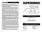
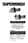
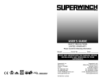
GARANTIE LIMITÉE
VALABLE A TRAVERS LE MONDE
GARANTIE LIMITÉE. Superwinch, Inc. (le “Vendeur”) garantit à l’acheteur d’origine (“vous”) que
toutes les pièces et composants, sont sans vice de matériaux ou de fabrication, et ce, pendant une
période d’un (1) an à compter de la date d’achat prouvable. Tout produit Superwinch défectueux
sera réparé ou remplacé sans dépenses de votre part si vous respectez ces procédures. Les
garanties énoncées par les présentes sont exclusives tiennent lieu de toutes autres garanties
expresses ou implicites.
PROCÉDURE DE RECOURS À LA GARANTIE LIMITEE.
Dès découverte d’un produit Superwinch défectueux, vous devrez envoyer à Superwinch, à l’usine
ou à un Centre de réparation autorisé par l’usine, une notification écrite dudit défaut et vous
devrez envoyer par courrier ou autre service de livraison le Superwinch défectueux, port et frais
postaux payés à l’avance. Les réparations ou remplacements par le Vendeur conformément à la
présente Garantie s’effectueront normalement dans les quinze (15) jours ouvrables suivant réception du Superwinch défectueux. Le Vendeur ou ses Agents autorisés peut facturer des frais
raisonnables pour les pièces et la main d’oeuvre en cas de réparation non couverte par la présente
Garantie limitée.
LIMITATIONS ET EXCLUSIONS EN CE QUI CONCERNE LA GARANTIE ET LES REMÈDES.
La réparation et/ou le remplacement de tout Superwinch défectueux ou de tout composant d’un
tel Superwinch tel que convenu par les présentes est votre remède exclusif. Les exclusions et limitations de garanties et les limitations de REMEDES ci-dessous seront expressément applicables :
A. Garanties expresses . Le Vendeur garantit que le Superwinch est tel qu’il est décrit dans le
“Mode d’emploi Superwinch” fourni avec la présente; aucune autre garantie expresse n’est donnée en ce qui concerne le Superwinch. Si un modèle ou échantillon vous a été montRé, ledit modèle ou échantillon a été utilisé à des fins d’illustration uniquement et ne sera pas considéré une
garantie que le Superwinch sera conforme au modèle ou à l’échantillon.
B. Garantie implicite . LA GARANTIE IMPLICITE DE L’APTITUDE À LA VENTE ET TOUTE AUTRE
GARANTIE IMPLICITE S’APPLIQUERA UNIQUEMENT POUR UNE DURÉE D’UN (1) AN À COMPTER DE
LA DATE D’ACHAT PROUVABLE. CERTAINS ÉTATS AMÉRICAINS NE PERMETTENT PAS DE LIMITER LA
DURÉE DES GARANTIES IMPLICITES; IL EST DONC POSSIBLE QUE LA LIMITATION CI-DESSUS NE S’APPLIQUE PAS À VOTRE CAS.
C. Dommages indirects. SUJET AUX OBLIGATIONS DE LA GARANTIE LIMITÉE DU VENDEUR
ÉNONCÉES DANS LE PRÉSENT DOCUMENT, LE VENDEUR NE SERA AUCUNEMENT RESPONSABLE DE
DOMMAGES INDIRECTS, DE QUELQUE NATURE QUE CE SOIT, NI DE DOMMAGES INDIRECTS À LA
PROPRIÉTÉ, NI DE PERTES DE PROFITS, NI DE PERTES D’UTILISATION POUVANT SURVENIR À CAUSE
D’UN DÉFAUT, D’UN MAUVAIS FONCTIONNEMENT OU D’UNE PANNE QUELCONQUE DU SUPERWINCH CI-JOINT. CERTAINS ÉTATS AMÉRICAINS NE PERMETTENT PAS D’EXCLURE OU DE LIMITER
LES DOMMAGES INDIRECTS; IL EST DONC POSSIBLE QUE LA LIMITATION CI-DESSUS NE S’APPLIQUE
PAS À VOTRE CAS.
D. Condition de la garantie. Le Vendeur ne sera pas tenu de se conformer aux obligations de
garantie fournies par les présentes si la cause du défaut, du mauvais fonctionnement ou de la
panne du Superwinch est un dommage (ne résultant pas de composants défectueux ou qui fonctionnent mal) ou une utilisation déraisonnable par vous. Le terme Utilisation déraisonnable comprend mais ne est pas limité au manquement à la maintenance, à l’installation et à l’utilisation
raisonnables et nécessaires conformément aux consignes contenues dans le Mode d’emploi
Superwinch, et à l’utilisation du Superwinch pour des charges supérieures à celle figurant dans le
Mode d’emploi pour le modèle en question. La responsabilité du Vendeur sous la présente
garantie ou pour toute perte du produit Superwinch ou dommage à celui-ci ne dépassera pas le
coût de correction des défauts du produit Superwinch ou de remplacement de celui-ci, et lors de
l’expiration de la période de garantie, toute telle responsabilité prendra fin. Les agents, distributeurs et employés du Vendeur ne sont pas autorisés à modifier la présente garantie ni à donner
d’autres garanties complémentaires obligatoires pour le Vendeur. Toute déclaration supplémentaire, qu’elle soit écrite ou orale, ne constituera donc pas une garantie et ne devra pas être considérée comme valable.
REMEDES LÉGAUX DE L’ACHETEUR. Cette garantie limitée vous donne des droits légaux spécifiques et il est possible que vous ayez d’autres droits qui varient d’un état à l’autre aux Etats-Unis
et d’un pays à l’autre. Vous avez également des droits de garantie implicite. En cas de problème
avec le service ou la performance suivant la garantie limitée, il est possible que vous puissiez intenter une action en justice devant la Cour des Prudhommes (“small claims court”), devant le tribunal
d’état ou devant le tribunal fédéral des Etats-Unis ou dans une autre juridiction appropriée en
dehors des Etats-Unis.
QUESTIONS. Toute question en ce qui concerne le respect des garanties énoncées dans les
présentes doit être envoyée, par écrit, à : Superwinch, Inc., Winch Drive, Putnam, CT 08260 U.S.A.
ou à Superwinch Limited, Abbey Rise, Whitchurch Road, Tavistock, Devon PL 19 9DR, England
OWNER'S MANUAL
INSTALLATION • OPERATION • MAINTENANCE
SAFETY PRECAUTIONS • REPAIR PARTS
06212
ATV Wireless
Winch Control
!
CAUTION
READ AND UNDERSTAND THIS MANUAL BEFORE INSTALLATION
AND OPERATION OF YOUR SUPERWINCH PRODUCT.
Superwinch, Inc.
Winch Drive
Putnam, CT 06260
U.S.A.
Tel. (860) 928-7787
Fax (860) 963-0811
98-10984 Rev A 4/9/04
Superwinch, Ltd.
Abbey Rise, Whitchurch Road
Tavistock, Devon PL 19 9DR
England
Tel. (1822) 614101
Fax (1822) 615204
SAFETY PRECAUTIONS
The responsibility for safe operation of this switch ultimately rests with you,
the operator. Read and understand all safety precautions and operating
instructions before installing and operating the winch. Careless switch
operation can result in serious injury and/or property damage.
Throughout this manual, you will find notations with the following headings:
If you have any
questions or problems
with this product,
please call
1.877.257.7888
Do not return product
back to store.
!
DANGER
!
WARNING
!
CAUTION
Indicates an imminently hazardous situation
which, if not avoided, will result in serious
injury or death.
Indicates a potentially hazardous situation
which, if not avoided, could result in serious
injury or death.
Indicates a potentially hazardous situation which,
if not avoided, may result in minor or moderate
injury. This notation is also used to alert against
unsafe practices.
Note: Indicates additional information in the installation and operation
procedures of your winch.
KIT INCLUDES
Key chain wireless transmitters
2
Power distribution module
1
Antenna
1
2 pin green power connector with fuse holder
1
with red and black wires
1
2 pin white solenoid connector with blue and yellow wires
1
Hardware kit
1
4 pin green ignition lead with yellow wire
1
2
INSTALLATION INSTRUCTIONS
b. Attach the blue wire to the blue marked location on the solenoid.
c. Attach the yellow wire to the yellow-marked location on the
solenoid.
d. Attach the blue and yellow wires from the handlebar switch to the
piggy-back connector matching the colors accordingly.
Do not attempt to install wiring when the battery is
connected. Automotive batteries contain flammable
and explosive gases. Wear eye protection during installation and
remove all metal jewelry. Do not lean over battery while making
connections.
!
DANGER
Check to ensure that the vehicle ground and positive leads from the
battery are disconnected before performing any electrical work.
Step 1
Disconnect the battery before beginning
installation.
Step 7
Find the green 4 pin connector with the yellow and red stripe wire.
a. Locate a wire on your ATV that turns ON and OFF with the ignition.
b. Using the attached "T tap," plug the yellow with red stripe wire
into the ignition lead.
Step 2
Locate a place to mount the Power
Distribution Module by either using the
cable ties or screws provided.
Note: The Power Distribution Module should be located within 4
feet of the solenoid (the enclosed wires are 4 feet long; Figure 1).
!
!
CAUTION
CAUTION
Step 6
Find the green 2 pin connector with the red and black wires.
a. Connect the red wire to the positive terminal on the battery.
b. Connect the black wire to the negative terminal on the battery.
Figure 1
Be sure to keep components away from moving
parts, sharp objects, or hot areas of the machine.
When using self-tapping screws, ensure that there
are no components, wires, or parts that can be
damaged by the screws.
Step 3
Locate a place to mount the antenna,
i.e: to rack or frame (Figure 2).
Note: If you have trouble locating an ignition source, consult your dealer
or ATV owner's manual.
!
WARNING
!
CAUTION
Ensure that the wiring harness does not interfere
or come in contact with any hot or moving engine,
suspension, steering, braking or exhaust parts.
Do not force the plug into the socket. If it does
not plug into the socket easily, rotate the plug,
matching the tab in the socket to the keyway in
the plug.
Step 8
Secure all loose wires with cable ties.
Step 4
Run wire from antenna to power
distribution module.
Figure 2
Step 5
Find the white 2 pin connector with the yellow and blue wires attatched.
a. Attach the wires to the solenoid using the piggy-back connectors
on the end of the wires.
3
4
06212 Wire Diagram
Supplied
Connector
Yellow/Red Ignition
Blue from handlebar SW
15 AMP
ATO-STYLE FUSE
Existing
Handlebar
Switch
Yellow from handlebar SW
15
TO POSITIVE (+)
POST OF
BATTERY
BLUE
YELLOW
BATTERY (+)
BATTERY (-)
GREEN
2-PIN CONNECTOR
WHITE
2-PIN CONNECTOR
COMMON
NEGATIVE
YELLOW WI RE
(FROM MODULE)
BLUE WI RE
(FROM MODULE)
SYSTEM GROUND
(JUMPER TO CEN TER
SPADE TERMINAL #2)
SYSTEM POWER
3
A B
2
C D
2
POWER DISTRIBUTION
MODULE
NEGATIVE TO POST D
D
BATTERY
Blue Wire
YELLOW
WI RE
(TO WINCH
)
(to
winch)
TO NEGETIVE (-)
POST OF
BATTERY
1
A
C
FUSE PROTECTION
B
POSITIVE TO POST A
GREEN
4-PIN CONNECTOR
WHITE
4-PIN CONNECTOR
Yellow
BLUE WIWire
RE
(TO WINCH
)
(to
winch)
YELLOW AND RED STRIPE
IGNITION LEAD
R
Yellow
BLUEWinch
WINCH
LEAD
Lead
ANTENNA
WINCH
Blue WINCH
Winch
YELLOW
Lead
LEAD
5
6
NOTES
OPERATION TEST
!
WARNING
Before testing winch operation, be sure to
reel off approximately two feet of wire rope
1. Turn ignition “ON.”
2. Put winch in “Free Spool” (if applicable). Pull out two (2) feet of rope.
3. Locate wire rope OUT button.
4. Test cable-OUT button.
5. Test cable-IN button.
6. Turn ignition OFF, make sure switch does not function in the OFF position.
REPLACEMENT PARTS LIST
Description
Part Number
REPLACEMENT PARTS
LIST
Qty.
Power Distribution Module
98-17294
1
Antenna
98-17292
1
Key Chain Remote
98-17295
1
7