1
2.7
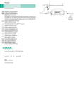
Output power diagrams
Representation of the output power as a function of the load resistance.
3.
Preparation and setup
Non-compliance with the following instructions will preclude all responsibility and liability in this respect on the part of Aesculap.
Ź When setting up and operating the product, adhere to
– national regulations for installation and operation,
– national regulations on fire and explosion protection.
Note
For the safety of patients and users it is essential that the mains power cord
and, especially, the protective earth connection are intact. In many cases
defective or missing protective earth connections are not registered immediately.
Ź Connect the device via the potential equalization terminal at the rear
panel of the device to the potential equalization system of the room
used for medical purposes.
Fig. 2
Output power diagram Caiman 12 mm Seal & Cut instrument
family
Note
The potential equalization lead can be ordered from the manufacturer as
article no. GK535 (4 m length) or TA008205 (0.8 m length).
Ź In order to ensure sufficient ventilation and cooling of the HF genera-
tor, leave at least 10 cm to 15 cm of space around the HF generator.
3.1
First use
WARNING
Fig. 3
Output power diagram Caiman 5 mm Seal & Cut instrument
family
2.8
Maximum peak output voltage (Up)
Risk of injury and/or product malfunction due to
incorrect operation of the electromedical system!
Ź Adhere to the instructions for use of any medical device.
Note
The following data allow the user to judge whether the HF generator
GN200 is suitable for a given accessory (insulation rating).
WARNING
Risk of injury to patient or user caused by inadequate accessories (insulation rating)!
Ź Make certain that the accessory voltage rating
specified in the product documentation is
higher than maximum peak output voltage.
Maximum peak output voltage (Up): 200 V
7