1
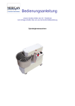
IMPASTATRICE
ELETTRICA
Manuale delle istruzione per l’uso
ART. 2200
I
GB
F
D
E
IMPASTATRICE
ELETTRICA
ELECTRIC MIXER
PETRIN ELECTRIQUE
ELEKTRISCHE
KNETMASCHINE
AMASADORA
ELÉCTRICA
10-2009-IMPASTATRICI-A5.doc
ART. 2200 TOP
ART. 2400
ART. 2500
MANUALE DELLE
ISTRUZIONE
OPERATING MANUAL
MODE d’EMPLOI et
d’ENTRETIEN
GEBRAUCHSANWEISUNG
MANUAL DE
INSTRUCCION
ISTRUZIONI ORIGINALI
Pag.
1
di
32
1.
2.
2.1.
2.2.
2.3.
3.
3.1.
3.2.
3.3.
3.4.
3.5.
4.
4.1.
4.2.
4.3.
4.4.
4.5.
5.
5.1.
5.2.
5.3.
5.4.
5.5.
5.6.
5.7.
6.
6.1.
6.2.
6.3.
6.3.1.
6.3.2.
6.4.
6.5.
6.6.
7.
7.1.
7.2.
8.
INDICE
CONSISTENZA DELLA FORNITURA
ORGANIZZAZIONE DEL CONTENUTO E CONSULTAZIONE
SCOPO DEL MANUALE
RESPONSABILITÀ
SIGNIFICATO DELLA SIMBOLOGIA
INFORMAZIONI GENERALI E CARATTERISTICHE
COLLAUDI EFFETTUATI PRIMA DELLA CONSEGNA
DESTINAZIONE USO E PARTI COSTRUTTIVE
CONFIGURAZIONI
CONDIZIONI DI SERVIZIO
USO NORMALE, USO IMPROPRIO, USO NON CORRETTO O VIETATO
ISTRUZIONI PER LA SICUREZZA
OBBLIGHI E DOVERI
AMBIENTI E POSTI DI LAVORO
AVVERTIMENTI IN MERITO AI RISCHI RESIDUI
TARGHE
DISPOSITIVI DI PROTEZIONE SULLA MACCHINA
TRASPORTO, MESSA IN SERVIZIO ED USO
POSTAZIONI DI LAVORO E MANSIONI DEGLI OPERATORI
TRASPORTO, MOVIMENTAZIONE IMMAGAZZINAGGIO
RIMOZIONE IMBALLO - MODALITÀ DI APERTURA
OPERAZIONI PRELIMINARI DI PREPARAZIONE
MONTAGGIO / SMONTAGGIO
DISPOSITIVI E FUNZIONI DI COMANDO
DESCRIZIONE DEL FUNZIONAMENTO
MANUTENZIONE, RICERCA GUASTI E PULIZIA
REQUISITI DEL MANUTENTORE
PRESCRIZIONI DI MANUTENZIONE
MANUTENZIONE ORDINARIA
MANUTENZIONE ORDINARIA ESEGUIBILE DALL’OPERATORE
MANUTENZIONE ORDINARIA ESEGUIBILE DAL MANUTENTORE
MANUTENZIONE STRAORDINARIA
RICERCA GUASTI O AVARIE E SBLOCCO ELEMENTI MOBILI
PULIZIA
DEMOLIZIONE E SMALTIMENTO
DEMOLIZIONE
SMALTIMENTO
MATERIALI DI COSTRUZIONE
6
7
7
8
8
9
9
9
10
10
11
12
12
13
13
15
16
17
17
18
19
19
21
21
24
26
26
26
27
27
27
28
29
30
31
31
31
32
GARANZIA
Tutte le parti componenti le apparecchiature, escluse le parti elettriche, godono di una garanzia di 36 mesi, sempre che i difetti
siano dovuti alla costruzione. La spedizione dei pezzi in oggetto avverrà in porto assegnato. I pezzi sostituiti in garanzia
saranno comunque fatturati; al ricevimento dei pezzi (rispediti in porto franco), di cui è stata richiesta la sostituzione, si
provvederà con nota di credito. La garanzia non contempla la sostituzione dell’ apparecchiatura. La garanzia non contempla le
spese di manodopera per la sostituzione dei ricambi e qualsiasi altra spesa accessoria.
SPEDIZIONI
La merce viaggia a rischio e pericolo del Cliente. Eventuali contestazioni sullo stato difettoso del materiale dovranno essere
evidenziate al trasportatore al momento dell’accettazione della merce. Vi preghiamo di tenere nella dovuta considerazione
quanto oggetto della responsabilità del vettore e della inderogabilità della evidenziazione di eventuali danni al momento
dell’accettazione della merce. Sottolineiamo che la nostra Ditta non risponde di danni non evidenziati al vettore al momento
del ritiro della merce, anche se la stessa è stata inoltrata in porto franco con addebito in fattura.
FORO COMPETENTE
Per ogni controversia è competente il foro territorialmente competente della sede del costruttore.
Manuale delle istruzioni per l’uso
Edizione
10.2009
10-2009-IMPASTATRICI-A5.doc
ISTRUZIONI ORIGINALI
Pag.
2
di
32
MANUALE d’USO e MANUTENZIONE
MANUAL for USE and MAINTENANCE
MODE d’EMPLOI et d’ENTRETIEN
GEBRAUCHSANWEISUNG und WARTUNG
MANUAL de USO y MANUTENCION
Prodotto • Product • Produit • Produkt • Producto
IMPASTATRICE ELETTRICA
Modelli • Models • Modéles • Modell • Modelo
2200
S05
S25
S07
S38
S12
S42
S16
S70
S12
S38
S16
S42
S25
S12
S25
S16
S38
S60
S90
Modelli • Models • Modéles • Modell • Modelo
2200 TOP
Modelli • Models • Modéles • Modell • Modelo
2400
Modelli • Models • Modéles • Modell • Modelo
2500
Trifase • Triphase • Triphasé • Dreiphasig • Trifase
Monofase • Monophase • Monophasé • Einphasig • Monofase
10-2009-IMPASTATRICI-A5.doc
ISTRUZIONI ORIGINALI
3 PE AC 400 V 50 Hz
3 PE AC 400V 60Hz
1 N PE AC230V 50Hz
1 N PE AC 110V 60Hz
Pag.
3
di
32
DICHIARAZIONE CE DI CONFORMITÀ
2006/42/CE (Allegato II parte A)
Il sottoscritto, rappresentante il seguente costruttore
Costruttore
Indirizzo
ha incaricato di la persona autorizzata a costituire e conservare il fascicolo tecnico
Nome
Indirizzo
Il sottoscritto costruttore dichiara qui di seguito che la macchina
Denominazione generica / commerciale
IMPASTATRICE ELETTRICA
Funzione
Impastatrice con vasca rotativa utilizzata per il trattamento di vari
ingredienti
Modello
ART. 2200 / ART. 2200 TOP / ART. 2400 / ART. 2500
Tipo
________
Matricola
________
Anno di costruzione
20__
risulta in conformità a tutte le diposizioni pertinenti previste dalle seguenti direttive comunitarie (comprese tutte le
modifiche applicabili)
2006/42/CE - Direttiva Macchine
2006/95/CE - Direttiva Bassa Tensione
2004/108/CE - Direttiva Compatibilità Elettromagnetica
Le parti costituenti la macchina e destinate a venir a contatto con il prodotto alimentare sono conformi al:
REGOLAMENTO CE n. 1935/2004
REGOLAMENTO CE n. 2023/2006
10-2009-IMPASTATRICI-A5.doc
ISTRUZIONI ORIGINALI
Pag.
4
di
32
L'elenco delle principali norme applicate è allegato alla presente dichiarazione.
Norme armonizzate di tipo “A”
EN ISO 12100-1:2003+A1:2009
EN ISO 12100-2:2003+A1:2009
EN 14121-1:2007
Norme armonizzate di tipo “B”
EN ISO 13857:2008
EN 349:1993+A1:2008
EN ISO 13850:2008
EN 953:1997+A1:2009
EN 954-1:1996, EN ISO 13849-1:2008
EN 999:1998+A1:2008
EN 1037:1995+A1:2008
EN 1088:1995 + A1:2007+A2:2008
EN 60204-1:2006
EN ISO 14159:2008
Norme armonizzate di tipo “C”
EN 1672-2:2005+A1:2009
EN 453:2000+A1:2009
Altre norme e/o specifiche tecniche
EN 60073:2002
EN 60445:2007
EN 60446:2007
EN 60447:2004
EN 60529:1992+A1:2000
EN 61293:1994
EN 61310-1:2008
EN 61310-2:2008
EN 61310-3:2008
................................................................................................(luogo). .......................................(data).
(firma)
_____________________
Legale Rappresentante
10-2009-IMPASTATRICI-A5.doc
ISTRUZIONI ORIGINALI
Pag.
5
di
32
1.
CONSISTENZA DELLA FORNITURA
L’Impastatrice Elettrica nel seguito denominata “macchina”, è progettata per amalgamare impasti, sia duri che soffici, formati
da farina, sali, leviti, grassi e liquidi (acqua, uova, ...), patate e macinati di carne ed altri ingredienti nell'industria nei negozi
alimentari.
A seconda del modello ed alle richieste commerciali, la macchina può essere costituita con diverse configurazioni, optional e
dati tecnici, secondo le combinazioni, individuate ed identificate al capitolo n. 2.
La macchina fornita ed oggetto del presente manuale delle istruzioni per l’uso, è costituita con gruppi e parti di cui alla
dichiarazione CE di conformità.
La macchina è provvista di targhetta di identificazione sulla quale sono riportati i seguenti dati:
[fac simile]
DESIGNAZIONE
SERIE/MODELLO
MATRICOLA
MASSA DELLA MACCHINA
ANNO DI COSTRUZIONE
TENSIONE NOMINALE
CORRENTE A PIENO CARICO
CORRENTE DI CORTO CIRCUITO
NUMERO DI SCHEMA ELETTRICO
IMPASTATRICE ELETTRICA
_________
_________
___ kg
20 ___
... PE AC .... V .... Hz
…A
… kA
…
Per informazioni sul corretto utilizzo della macchina, consultare il manuale di istruzioni
10-2009-IMPASTATRICI-A5.doc
ISTRUZIONI ORIGINALI
Pag.
6
di
32
2.
ORGANIZZAZIONE DEL CONTENUTO E CONSULTAZIONE
2.1. SCOPO DEL MANUALE
IMPORTANZA DEL MANUALE
Il presente manuale delle istruzioni per l’uso è da considerarsi come parte integrante della macchina:
1.
deve essere custodito per tutta la vita della macchina.
2.
deve accompagnare la macchina in caso di cessione della stessa.
3.
oltre a riportare tutte le notizie utili per gli operatori, contiene (raccolti in capitoli specifici), gli schemi elettrici che
serviranno per gli eventuali interventi di manutenzione e riparazione.
SCOPO / FINALITÀ DEL MANUALE
Il Manuale delle istruzioni per l’uso ha lo scopo di fornire al committente tutte le informazioni necessarie affinché, oltre ad un
adeguato utilizzo della macchina fornita, sia in grado di gestire la stessa nel modo più autonomo e sicuro possibile. Inoltre il
presente manuale è stato redatto allo scopo di fornire indicazioni ed avvertenze per conoscere la macchina fornita, per
comprendere i suoi principi e limiti di funzionamento. Per eventuali dubbi interpellare il Centro di Assistenza Autorizzato.
Questo manuale delle istruzioni per l’uso è stato realizzato esclusivamente per l’utilizzatore della macchina e
contiene informazioni di proprietà riservata del costruttore.
I testi, i disegni e gli schemi contenti nel presente manuale delle istruzioni per l’uso, sono di natura tecnica
riservata e di proprietà del fabbricante della macchina e non possono essere riprodotti in alcun modo né
parzialmente né integralmente.
Senza la preventiva autorizzazione scritta del costruttore, questo manuale o parte di esso non può essere
riprodotto in nessuna forma, modificato, trascritto, tradotto in qualsiasi lingua, reso disponibile a terzi o
comunque usato in modo che possa pregiudicare gli interessi del costruttore.
Ogni abuso sarà perseguito ai sensi di legge e sui diritti d’autore. © Copyright 2009
DESTINATARI
Il presente manuale delle istruzioni per l’uso, consegnato in n. 1 copia assieme alla macchina, viene fornito come parte
integrante dello stesso, è rivolto sia agli operatori che ai tecnici qualificati abilitati all’installazione, uso e manutenzione.
Il responsabile del servizio di prevenzione e protezione del committente e gli ulteriori addetti cui è destinata la macchina,
devono prendere visione del presente manuale delle istruzioni per l’uso, al fine di adottare tutte le misure tecniche ed
organizzative
Prima di mettere in funzione la macchina, ed ogniqualvolta si presenti un dubbio circa il suo funzionamento, è fatto obbligo
all’operatore di leggere attentamente le istruzioni di uso.
CONSERVAZIONE
¾
Il presente Manuale delle istruzioni per l’uso deve essere conservato nelle immediate vicinanze della
macchina al riparo da liquidi, da umidità, eccessivo calore e quant’altro ne possa compromettere lo stato
di leggibilità.
¾
Consultare il Manuale in modo da non danneggiare tutto od in parte il contenuto.
¾
Non asportare pagine dal Manuale.
¾
Non scrivere sulle pagine del Manuale
AGGIORNAMENTI, INTEGRAZIONI E SOSTITUZIONE
¾
Nel caso il presente manuale subisca danneggiamenti o venga smarrito, è possibile richiederne copia al
Centro di Assistenza Autorizzato.
¾
Il presente manuale rispecchia lo stato della tecnica al momento della costruzione della macchina; il
costruttore si riserva il diritto di aggiornare la produzione e di conseguenza altre edizioni del manuale,
senza l’obbligo di aggiornare produzioni o manuali precedenti, se non in casi particolari riguardanti la
salute e la sicurezza delle persone.
¾
Nel caso il committente desideri ricevere ulteriori informazioni, è pregato di contattare direttamente al
Centro di Assistenza Autorizzato.
¾
Il committente è invitato, in caso di cessione della macchina, a segnalare al Centro di Assistenza
Autorizzato i dati identificativi del nuovo destinatario, per facilitare la trasmissione di eventuali
integrazioni al manuale che, come già ricordato, deve accompagnare il contenitore/distributore rimuovile
anche in caso di trasferimento.
10-2009-IMPASTATRICI-A5.doc
ISTRUZIONI ORIGINALI
Pag.
7
di
32
2.2. RESPONSABILITÀ
¾
Nel caso il presente manuale subisca danneggiamenti o venga smarrito, è possibile richiederne copia al
Centro di Assistenza Autorizzato.
¾
Il presente manuale rispecchia lo stato della tecnica al momento della costruzione della macchina; il
costruttore si riserva il diritto di aggiornare la produzione e di conseguenza altre edizioni del manuale,
senza l’obbligo di aggiornare produzioni o manuali precedenti, se non in casi particolari riguardanti la
salute e la sicurezza delle persone.
¾
Porre particolare attenzione al contenuto dei rischi residui presenti sulla macchina e le prescrizioni a cui
devono attenersi gli operatori.
¾
Il costruttore si ritiene responsabile per la macchina nella sua originale configurazione.
¾
Il costruttore non si ritiene responsabile per danni arrecati dall’uso improprio o non corretto della
macchina e della documentazione o per danni arrecati dalla violazione di norme imperative, negligenza,
imperizia, imprudenza e non rispetto di norme regolamentari da parte del datore di lavoro, dell’operatore
o del manutentore e per ogni eventuale guasto causato da un uso irragionevole, improprio e/o sbagliato
¾
Il costruttore non si ritiene responsabile per le conseguenze causate dall’uso di parti di ricambio non
originali o di caratteristiche equivalenti.
¾
Il costruttore si ritiene responsabile solo per le informazioni riportate nella versione originale del
manuale in lingua italiana.
¾
L’inosservanza delle prescrizioni contenute in questo manuale provocherà l’immediato decadimento
della garanzia.
I responsabili di stabilimento, che sovrintendono alle attività lavorative, devono, nell’ambito delle rispettive
attribuzioni e competenze:
¾
attuare le misure di sicurezza previste;
¾
rendere edotti gli operatori dei rischi specifici cui sono esposti e portare a loro conoscenza le norme
essenziali di prevenzione;
¾
disporre ed esigere che i singoli operatori osservino le norme di sicurezza ed usino i mezzi di protezione
messi a loro disposizione:
¾
porre più di un operatore, contemporaneamente, al lavoro su tale manufatto.
Si precisa inoltre che a seguito della messa in servizio della macchina, la stessa è assoggettata a quanto previsto
/ prescritto dalla direttiva 89/655/CEE e successive modifiche
2.3. SIGNIFICATO DELLA SIMBOLOGIA
Di seguito viene chiaramente specificato il significato dei simboli e delle definizioni che verranno utilizzate nel presente
documento.
PERICOLO
Indica la presenza di un pericolo per chi opera sulla macchina e per chi si trova nelle vicinanze perciò l’attività
segnalata deve essere svolta nel rispetto delle norme antinfortunistiche vigenti e delle indicazioni riportate nel
presente manuale.
PRECAUZIONE
Indica un’avvertenza su informazioni utili e/o ulteriori raccomandazioni e/o accorgimenti inerenti l’operazione
in corso.
ATTENZIONE
Indica un’operazione da eseguire con attenzione per evitare di arrecare danno alla macchina.
10-2009-IMPASTATRICI-A5.doc
ISTRUZIONI ORIGINALI
Pag.
8
di
32
3.
INFORMAZIONI GENERALI E CARATTERISTICHE
3.1. COLLAUDI EFFETTUATI PRIMA DELLA CONSEGNA
Prima della consegna, presso la sede del costruttore, la macchina è stata sottoposta ai test di sicurezza previsti della
legislazione vigente ed applicabile ed alle prove di funzionamento secondo la destinazione d’uso definita nel presente manuale
delle istruzioni per l’uso. Inoltre tutti i componenti installati vengono sottoposti a minuzioso controllo sia visivo che
strumentale, al fine di garantire la rispondenza anche alle richieste contrattuali.
3.2. DESTINAZIONE USO E PARTI COSTRUTTIVE
L’Impastatrice Elettrica nel seguito denominata “macchina”, è progettata per amalgamare impasti, sia duri che soffici, formati
da farina, sali, leviti, grassi e liquidi (acqua, uova, ...), patate e macinati di carne ed altri ingredienti nell'industria nei negozi
alimentari.
La macchina è generalmente costituita dai seguenti elementi (cfr. allegato):
1.
n. 1 struttura costituita da un’unica fusione, che sostiene e contiene gli organi motore ed i dispositivi di comando.
In alcuni modelli, la parte superiore della macchina, ovvero la testa, può essere ribaltata per consentire la
sostituzione dell’utensile, la rimozione della vasca ed il carico/scarico del prodotto alimentare. La posizione di
chiusura della testa è garantita tramite un aggancio meccanico rapido; mentre la posizione di aperto è garantita da
un apposito cilindro precaricato;
2.
n. 1 vasca contenente i prodotti alimentari da impastare posta nella zona anteriore della macchina e fissata alla
stessa. La vasca ruota meccanicamente in senso orario, per effetto di un motore elettrico avviato direttamente.
Nelle macchine con testa ribaltabile, la vasca può essere rimossa manualmente;
3.
n. 1 utensile di impasto su un asse fisso verticale, posto sulla testa della macchina che ruota all’interno della
vasca.. L’utensile può essere a forma di spirale o spatola. L’utensile ruota meccanicamente per effetto di rinvii
meccanici, comandato dallo stesso motore impiegato per la rotazione della vasca; in alcuni modelli l’utensile ruota
per effetto di un secondo motore elettrico avviato direttamente. Nelle macchine con testa ribaltabile, l’utensile può
essere rimosso manualmente per la sua sostituzione e pulizia.
4.
n. 1 spacca impasto costituito da un’asta metallica fissa, montata sulla testa della macchina, posta davanti
all’utensile. Lo spacca impasto consente un migliore impasto dei prodotti alimentari e di far amalgamare in modo
uniforme tutti i prodotti alimentari;
5.
n. 1 un riparo mobile interbloccato che ricopre la parte superiore della vasca in movimento e che quando aperto
utilizzando un interblocco applicato al sistema di comando, determina l’arresto entro 4 secondi degli elementi
mobili pericolosi. Il riparo mobile può essere pieno o pieno con apertura nella zona anteriore in materiale
trasparente, oppure in un reticolato di acciaio. Nelle versioni con riparo non pieno, è consentita l’alimentazione
manuale degli ingredienti secchi con vasca in posizione di lavoro.
I motori elettrici possono essere monofase oppure trifase ad una o più velocità (cfr. dati tecnici).
Tutte le parti della macchina destinate a venire a contatto con i prodotti alimentari, quali vasca, utensili, spacca pasta, etc…
sono in materiali di acciaio inox o materiale plastico destinato a venire a contatto con gli alimenti.
Le funzioni automatiche, la programmazione e la sequenza operativa della macchina, compresi i tempi di ritardo per l’arresto
dell’utensile, la selezione delle velocità etc…, sono gestite da componenti elettromeccanici ed elettronici, in logica cablata,
tramite il pannello di comando e controllo posto nella zona anteriore della macchina (cfr. allegato)
A seconda delle esigenze di funzionamento e di produzione, la macchina può essere costituita con le diverse parti opzionali
(cfr. dati tecnici).
Gli eventuali ulteriori ingredienti impiegabili, non devono essere rischiosi per la salute dell’operatore e del
manutentore. Inoltre non devono determinare zone potenzialmente esplosive. Consultare sempre i fati tecnici e
le schede di sicurezza relative ai pericoli di ogni prodotto alimentare.
Eventualmente se si generano zona polverose, indossare adeguate mascherina protettive, sia durante il carico
manuale, sia durante la lavorazione della macchina.
10-2009-IMPASTATRICI-A5.doc
ISTRUZIONI ORIGINALI
Pag.
9
di
32
3.3. CONFIGURAZIONI
Per i dati tecnici di dettaglio, la produzione ed i disegni meccanici, cfr. allegato.
DATI TECNICI
ART. 2200
ART. 2200 TOP
TESTA FISSA
TESTA RIBALTABILE
VASCA FISSA
VASCA RIMOVIBILE
VASCA BORDO ARROTONDATO
VASCA BORDO PIATTO
UTENSILE A SPIRALE
UTENSILE A SPATOLA
UTENSILE FISSO
UTENSILE INTERCAMBIABILE
UNICO MOTORE PER VASCA E UTENSILE
UN MOTORE PER VASCA ED UNO PER
UTENSILE
MOTORE TRIFASE
MOTORE TRIFASE DUE VELOCITÀ
MOTORE MONOFASE
COMANDI ELETTROMECCANICI
COMANDI ELETTRONICI CON TIMER DI
RITARDO ARRESTO
COMANDI ELETTRONICI CON TIMER PER
COMMUTAZIONE VELOCITÀ
ART. 2400
ART. 2500
3.4. CONDIZIONI DI SERVIZIO
DATI
Livello di potenza acustica continuo
equivalente ponderato A
Natura della corrente - Frequenza
Valore a pieno carico della corrente
Tensione nominale d’impiego
Corrente presunta ammissibile di
corto circuito nominale condizionata
Massa e neutro
Grado di protezione
Posizionamento della macchina
Luogo d’impiego
Temperatura massima dell’aria
ambiente di lavoro
Illuminazione minima richiesta
Ulteriori condizioni d’impiego
ART. 2200 - ART. 2200 TOP – ART- 2400 – ART. 2500
Minore di 70dBA
Cfr. targa della macchina
Cfr. targa della macchina
Cfr. targa della macchina
6 kA simmetrici
TT e TN
IP X3
Banco di lavoro impiegato nel settore alimentare di altezza compresa tra
900/1100mm dal piano di calpestio di adeguata portata, in cui si possa
liberamente circolare attorno alla macchina con uno spazio libero di almeno
800mm
All’interno
+40°C
500 lux
Macchina inadeguata per funzionamento in ambienti in cui siano presenti agenti
contaminanti: per esempio polveri, acidi, gas corrosivi, sale e simili
Macchina inadeguata per funzionamento in ambienti in cui siano presenti
atmosfere potenzialmente esplosive classificate come zona 0 o zona 1 o zona 2.
Macchina inadeguata per funzionamento in ambienti in cui siano presenti
radiazioni ionizzanti e non ionizzanti: per esempio microonde, raggi ultravioletti,
laser, raggi X e simili
Equipaggiamento elettrico inadeguata per essere equipaggiato a macchine o per
funzionare in ambienti in cui siano presenti vibrazioni ed urti: in caso contrario
montarlo lontano dall’apparecchiatura prevedere supporti antivibranti
DISPOSITIVO DI PROTEZIONE RACCOMANDATO CONTRO LE SOVRACORRENTI
Tensione Nominale d’isolamento
Ui = > 690 V
Corrente Nominale
In = > vedere schema elettrico
Regolazione relè magnetico
Im = < vedere schema elettrico
Regolazione relè termico
Ir = vedere schema elettrico
Valore massimo dell’impedenza dell’anello di
0.1 Ω
guasto
10-2009-IMPASTATRICI-A5.doc
ISTRUZIONI ORIGINALI
Pag.
10
di
32
3.5. USO NORMALE, USO IMPROPRIO, USO NON CORRETTO O VIETATO
La macchina descritta nel presente manuale delle istruzioni per l’uso è prevista per essere impiegata da un solo operatore
addestrato ed edotto sui rischi residui, ma con le competenze, in materia di sicurezza, degli addetti alla manutenzione.
Nel suo USO NORMALE, e ragionevolmente prevedibile, la macchina può essere utilizzata soltanto per
amalgamare impasti, sia duri che soffici, formati da farina, sali, leviti, grassi e liquidi (acqua, uova, ...), patate e
macinati di carne ed altri ingredienti nell'industria nei negozi alimentari.
La macchina non deve essere utilizzata IN MODO IMPROPRIO; in particolare:
1.
non deve essere impiegata per usi domestici,
2.
non deve essere fatta funzionare con parametri diversi da quelli riportati nella tabella delle caratteristiche
tecniche,
3.
per ogni uso della macchina con modalità diverse da quelle indicate nel presente manuale, il costruttore
ne declina ogni responsabilità,
4.
l’utilizzatore è responsabile dei danni risultanti dalla mancata osservanza delle condizioni di esercizio
concordate in sede di specifica tecnica e di conferma d’ordine,
5.
non fare funzionare la macchina a vuoto,
6.
non manomettere o deteriorare volutamente né rimuovere o nascondere le etichette.
La macchina non deve essere utilizzata IN MODO NON CORRETTO ovvero VIETATO in quanto si
potrebbero causare danni o ferite per l’operatore; in particolare:
1.
è vietato spostare la macchina quando è allacciata all’alimentazione elettrica;
2.
è vietato tirare il cavo di alimentazione elettrica o la macchina per scollegare la spina di
alimentazione,
3.
è vietato porre dei pesi sulla macchina o sul cavo di alimentazione elettrica,
4.
è vietato posizionare il cavo di alimentazione elettrica su parti taglienti o con pericolo di ustione,
5.
è vietato l’impiego della macchina con il cavo di alimentazione elettrica od i dispositivi di comando
danneggiati e non integri;
6.
è vietato lasciare la macchina spenta con il cavo di alimentazione elettrica allacciato alla spina di
alimentazione,
7.
è vietato lasciare la macchina caricata incustodita;
8.
è vietato infilare qualsiasi tipo di oggetto all’interno della calotta di ventilazione del motore;
9.
è vietato posizionare la macchina sopra oggetti diversi da un banco di lavoro impiegato nel settore
alimentare di altezza compresa tra 900 - 1100mm dal piano di calpestio,
10. è vietato infilare qualsiasi tipo di oggetto sotto il basamento della macchina o posizionare panni o altro
tra i piedini di appoggio della macchina ed il banco di lavoro,
11. è vietato l’impiego di sostanze infiammabili, corrosive o nocive per la pulizia,
12. è vietato immergere la macchina in acqua o altri liquidi;
13. è vietato l’utilizzo a personale non autorizzato e con vestiario diverso da quello indicato per l’uso,
14. è vietato introdurre prodotti od oggetti aventi caratteristiche diverse da quelle indicate nell’uso
normale, quali per es. ossa, carne congelata, prodotti non alimentari, od altri oggetti quali sciarpe, etc…,
15. è vietato il funzionamento con i ripari di protezione e fissi non bloccati correttamente o asportati;
16. è vietata la parziale o totale neutralizzazione, rimozione, modifica o rendere comunque inefficaci le
protezioni, dei micro interruttori di sicurezza e delle segnalazioni di pericolo.
17. è vietato il funzionamento senza che siano stati adottati da parte dell’utilizzatore tutti i provvedimenti
circa l’eliminazione dei rischi residui,
18. è vietato fumare od usare apparecchi a fiamma libera e manipolare materiali incandescenti, a meno
che non siano adottate idonee misure di sicurezza,
19. è vietato azionare o regolare i dispositivi di controllo e di bloccaggio quali pomelli o simili sia
durante il funzionamento della macchina, sia se non si è autorizzati
20. è vietato impiegare ingredienti rischiosi per la salute dell’operatore e del manutentore. Inoltre non
devono determinare zone potenzialmente esplosive, in quanto la macchina non è adeguata per l’impiego
o trattare prodotti che determinano zone potenzialmente esplosive.
L’utilizzatore è comunque responsabile dei danni risultanti dalla mancata osservanza delle condizioni di uso
normale specificate. Per eventuali dubbi rivolgersi al Centro di Assistenza Autorizzato.
10-2009-IMPASTATRICI-A5.doc
ISTRUZIONI ORIGINALI
Pag.
11
di
32
4.
ISTRUZIONI PER LA SICUREZZA
La mancata applicazione delle norme e procedure di sicurezza può essere fonte di pericolo e di danno.
La macchina s’intende vincolata nell’uso al rispetto, da parte dell’utente finale, di:
1.
tutte le regole, d’inserimento nell’ambiente e di comportamento delle persone, stabilite dalle leggi e/o
norme applicabili; con particolare riferimento all’impianto fisso a monte della macchina fornita e per il
suo allacciamento/funzionamento;
2.
tutte le ulteriori istruzioni e avvertenze d’impiego facenti parte della documentazione tecnico/grafica
annessa alla macchina stessa.
4.1. OBBLIGHI E DOVERI
REQUISITI GENERALI DEL PERSONALE
Il personale che interagisce con la macchina deve:
a.
avere letto e compreso tutte le prescrizioni di sicurezza riportate nel manuale delle istruzioni per l’uso;
b.
presentare condizioni psicofisiche normali;
c.
essere precedentemente informato e formato circa:
c.1.
i pericoli di ferite o altri danni che possano derivare da contatti diretti o indiretti;
c.2.
i pericoli causati da sovratemperature, archi elettrici o radiazioni prodotti e/o emessi dall’apparecchiatura
elettrica eventualmente presente;
c.3.
i pericoli di natura non elettrica che, come insegna l’esperienza, possono derivare dal materiale elettrico
eventualmente presente;
c.4.
i pericoli di ferite o altri danni conseguenti ai rischi residui segnalati nel manuale delle istruzioni per l’uso;
d.
pertanto possedere (oppure acquisire tramite adeguata formazione ed addestramento), i seguenti requisiti:
d.1.
cultura generale e tecnica a livello sufficiente per comprendere il contenuto del presente Manuale delle istruzioni
per l’uso ed interpretare correttamente lo schema elettrico eventualmente allegato e tutti i disegni tecnici;
d.2.
conoscenza delle principali norme igieniche, antinfortunistiche e tecnologiche;
d.3.
conoscenza complessiva della macchina e dell’apparecchiatura elettrica eventualmente presente;
d.4.
sapere come comportarsi in caso di emergenza;
d.5.
sapere dove reperire i dispositivi di protezione individuale e come usarli correttamente se le indicazioni del
fabbricante lo prescrivono o se le protezioni collettive sono insufficienti;
e.
deve inoltre:
e.1.
segnalare immediatamente al datore di lavoro le deficienze dei dispositivi e dei mezzi di sicurezza e di
protezione, nonché le altre eventuali condizioni di pericolo di cui venissero a conoscenza, adoperandosi
direttamente, in caso di urgenza e nell’ambito delle loro competenze e possibilità per eliminare o ridurre dette
deficienze o pericoli;
e.2.
non rimuovere o modificare i dispositivi e gli altri mezzi di sicurezza e di protezione senza averne ottenuto
l’autorizzazione;
e.3.
non compiere, di propria iniziativa, operazioni o manovre che non siano di loro competenza e che possono
compromettere la sicurezza propria o di altre persone:
e.4.
non indossare anelli, orologi da polso, gioielli, capi di vestiario stracciati, sciarpe, cravatte, o qualunque altro
indumento o accessorio pendulo che possa essere fonte di rischio; serrare bene le maniche attorno ai polsi, e
tenere sempre ben raccolti i capelli.
Eccetto dove diversamente specificato, il personale che esegue gli interventi di installazione, allacciamento,
manutenzione, reinstallazione e riutilizzazione, ricerca guasti o avarie, demolizione e smantellamento
deve essere un personale esperto addestrato in materia di sicurezza ed edotto sui rischi residui, con le
competenze, in materia di sicurezza, degli addetti alla manutenzione.
Tutte le specifiche competenze, compiti e zone pericolose entro cui l’operatore ed il manutentore devono
intervenire per eseguire le funzioni del presente manuale, sono indicate nei capitoli che seguono.
Detto personale esperto deve essere in grado di valutare il lavoro assegnatogli e riconoscere i possibili
pericoli sulla base della propria preparazione, conoscenza ed esperienza professionale e della propria
conoscenza della macchina, dei relativi equipaggiamenti e delle relative normative; deve inoltre essere in
possesso di una adeguata qualifica professionale circa la macchina in questione. Deve essere addestrato in
materia di sicurezza ed edotto sui rischi residui.
Deve inoltre essere esperto e non avvertito, ovvero deve essere un tecnico diplomato o laureato con
conoscenze attinenti la macchina ed i relativi equipaggiamenti e le relative normative e che presenti una
particolare competenza tecnica o addestramento.
Egli oltre ad eseguire tutti i lavori di manutenzione, in alcuni casi è di supporto all’operatore per alcune
attività di attrezzaggio. Il manutentore, può inoltre accedere al quadro elettrico con l’equipaggiamento in
tensione.
10-2009-IMPASTATRICI-A5.doc
ISTRUZIONI ORIGINALI
Pag.
12
di
32
Per ragioni di sicurezza, durante le operazioni di lavorazione, nella zona circostante la macchina, non è
permessa la presenza di altre persone oltre all’operatore.
In deroga a questa prescrizione è consentita la presenza di personale di manutenzione espressamente
autorizzato dal responsabile di produzione.
Il personale addetto alla regolazione/registrazione, all’uso ed alla manutenzione deve immediatamente
sospendere le attività ed informare il datore di lavoro o il responsabile di reparto o il preposto qualora
dovessero riscontrare difetti o anomalie nel funzionamento.
In caso l’utilizzatore non dispone di personale esperto o avvertito, deve commissionare le attività in oggetto
ad una società competente a tale scopo, quale per esempio il fornitore dello stesso.
4.2. AMBIENTI E POSTI DI LAVORO
L’ambiente di lavoro deve rispondere ai requisiti della direttiva 89/654/CEE. Nell’area di lavoro non devono essere presenti
oggetti estranei.
Il datore di lavoro, nel rispetto della direttiva 89/391/CEE, concernente l'attuazione di misure volte a promuovere il
miglioramento della sicurezza e della salute dei lavoratori durante il lavoro, deve provvedere ad eliminare o ridurre i rischi
residui indicati come previsto nel presente manuale.
4.3. AVVERTIMENTI IN MERITO AI RISCHI RESIDUI
Il datore di lavoro deve provvedere ad istruire il personale sui rischi di infortunio, sui dispositivi di sicurezza
e sulle regole generali in tema di antinfortunistica previste dalle direttive comunitarie e dalla legislazione del
paese dove la macchina è installata.
È pertanto necessario che l’uso, le manutenzioni effettuate dall'utilizzatore e la pulizia, siano affidate a
personale addestrato e competente.
E’ responsabilità del datore di lavoro accertarsi che le istruzioni impartite siano state adeguatamente
recepite. Quando necessario, è inoltre responsabilità dell'utilizzatore:
1.
attivare un corso di formazione/addestramento, eventualmente in collaborazione con il costruttore della
macchina, in modo che gli operatori ed i manutentori siano adeguatamente istruiti sui rischi in
generale e sui rischi residui indicati nel presente manuale,
2.
la fornitura dei mezzi di protezione individuale conformi a quanto indicato nella direttiva 89/656/CEE
e successivi emendamenti ed aggiornamenti e l’informazione sugli usi consentiti.
RISCHIO RESIDUO DOVUTO AL RUMORE
La macchina produce, come da prove sperimentali effettuate, un livello di potenza acustica continuo
equivalente pesato A inferiore a 70 dB.
Per evitare i pericoli di offesa alle orecchie per rumori laceranti o insistenti, l’operatore, oltre ad essere
adeguatamente informato e formato, durante il funzionamento della macchina deve sempre utilizzare
dispositivi di protezione delle orecchie appropriati, quali per esempio cuffie o tappi protettivi o simili
protezioni auricolari personali.
RISCHIO RESIDUO DOVUTO AD INCENDIABILITÀ
Per evitare, i pericoli conseguenti ad un incendio, l’utilizzatore oltre a formare ed informare adeguatamente
l’operatore ed il manutentore, in prossimità del posto di lavoro della macchina, deve predisporre adatti
sistemi antincendio (per es. gli apparecchi estintori portatili di primo intervento) adeguati alla tipologia di
materiali che possono incendiarsi: quali per esempio le apparecchiature elettriche ed elettroniche
dell’equipaggiamento elettrico. L’acqua non deve essere usata per lo spegnimento di incendi.
RISCHIO RESIDUO DOVUTO AI SISTEMI DI COMANDO/CONTROLLO LEGATI ALLA SICUREZZA:
Si segnala che le funzioni di sicurezza ed i sistemi di comando/controllo legati alla sicurezza, sono realizzate in
conformità alla categoria 1 di sicurezza; tuttavia per effetto di un guasto può essere presente un
malfunzionamento, ovvero un rischio residuo dovuto ad un mancato arresto, secondo quanto previsto.
Dall’attivazione del comando di arresto della macchina o per assenza di energia elettrica di alimentazione, sia
l’operatore che il manutentore, prima di accedere alle parti mobili della macchina, devono accertarsi
dell’effettivo loro arresto, controllando visivamente dalla zona superiore della macchina, attraverso il
collo della macchina.
10-2009-IMPASTATRICI-A5.doc
ISTRUZIONI ORIGINALI
Pag.
13
di
32
RISCHIO RESIDUO DOVUTO ALLA RIMOZIONE DEI RIPARI FISSI, INTERVENTI SU PARTI
ROTTE/USURATE
Per qualsiasi evenienza l'operatore non deve mai tentare di aprire o rimuovere un riparo fisso o
manomettere un dispositivo di sicurezza.
Nella fase di attrezzaggio, di manutenzione e di pulizia, e durante tutte le ulteriori operazioni manuali
che avvengono introducendo le mani o altre parti del corpo nelle aree pericolose della macchina, permane un
rischio residuo dovuto soprattutto a:
1.
urti con parti costruttive della macchina,
2.
strisciamento e/o abrasione con parti ruvide della macchina,
3.
taglio con parti affilate degli utensili.
L’operatore ed il manutentore oltre ad essere adeguatamente informati e formati, ogni qualvolta eseguono le
operazioni di cui sopra, devono utilizzare dispositivi di protezione del capo, delle mani, dei piedi, vestiario
adeguato al luogo di lavoro e delle vie respiratorie, quali per esempio l'elmetto antiurto, guanti
antitaglio con fibre metalliche, calzature antiscivolo, resistenti ed adatte alla particolare natura del
rischio, con la punta di ferro.
Inoltre, l’operatore ed il manutentore devono essere addestrati per l'intervento connesso alle operazioni
manuali con ripari aperti, devono essere istruiti sui conseguenti rischi connessi e devono essere autorizzati da
persona responsabile.
RISCHIO RESIDUO DOVUTO AD OPERAZIONI DI SOLLEVAMENTO ED AGLI INTERVENTI CHE
RICHIEDONO OPERAZIONI MANUALI
Le operazioni di sollevamento e trasporto della macchina o di sue parti, sono operazioni manuali che
comportano un rischio residuo dovuto soprattutto a urti, schiacciamento, trascinamento, strisciamento o di
abrasione. Il responsabile delle operazioni di trasporto/movimentazione deve informare adeguatamente il
personale su questi rischi residui.
È presente un rischio residuo, di urto, abrasione, taglio, puntura e strisciamento, durante la manutenzione, la
pulizia e le ulteriori operazioni manuali, per l’operatore ed il manutentore dovuto anche alla necessita di
smontare e/o posizionare le parti degli utensili, etc…
Sia il personale addetto alla movimentazione sia l’operatore che il manutentore oltre ad essere adeguatamente
informati e formati ed a rispettare le modalità d’uso previste, devono utilizzare dispositivi di protezione del
capo, delle mani, dei piedi e vestiario adeguato al luogo di lavoro quali per esempio: l'elmetto
antinfortunistico, guanti antitaglio con fibre metalliche, calzature antiscivolo resistenti ed adatte alla
particolare natura del rischio con la punta di ferro.
RISCHIO DOVUTO AL POSSIBILE SCIVOLAMENTO E/O CADUTA
Per evitare, durante il normale utilizzo della macchina e durante gli interventi di manutenzione, i pericoli
di scivolamento e/o caduta sul piano di riferimento (di calpestio), l'operatore ed il manutentore, ad essere
adeguatamente informati e formati, devono sempre utilizzare dispositivi di protezione dei piedi
appropriati, quali per esempio calzature antiscivolo, resistenti ed adatte alla particolare natura del
rischio.
L'utilizzatore deve comunque essere mantenere pulito il piano di calpestio su cui si muovono l'operatore ed il
manutentore e privo di sostanze che facilitino lo slittamento, quali per esempio liquidi o qualsiasi tipi di
sostanza granulare o polverosa.
RISCHIO DOVUTO ALLA NATURA DEI PRODOTTI IMPIEGATI NELLA MACCHINA
La macchina, è progettata per amalgamare impasti, sia duri che soffici, formati da farina, sali, leviti, grassi e
liquidi (acqua, uova, ...), patate e macinati di carne ed altri ingredienti nell'industria nei negozi alimentari.
Gli eventuali ulteriori ingredienti impiegabili, non devono essere rischiosi per la salute dell’operatore e del
manutentore. Inoltre non devono determinare zone potenzialmente esplosive.
Consultare sempre i dati tecnici e le schede di sicurezza relative ai pericoli di ogni prodotto alimentare.
Eventualmente se si generano zona polverose, indossare adeguate mascherina protettive, sia durante il carico
manuale, sia durante la lavorazione della macchina.
10-2009-IMPASTATRICI-A5.doc
ISTRUZIONI ORIGINALI
Pag.
14
di
32
RISCHIO DOVUTO AL MANCATO FUNZIONAMENTO DEL SISTEMA CENTRALIZZATO DI ASPIRAZIONE
PREVISTO DALL’UTILIZZATORE
Durante le operazioni di carico dei prodotti secchi nella vasca o durante la normale lavorazione, si possono
determinare delle polveri sospese (per es. polvere di farina).
Gli ingredienti ed i prodotti confezionati devono essere maneggiati con cura, riducendo al minimo l'altezza al
di sopra della base della vasca da cui vengono versati.
Le confezioni devono essere aperte con cura nella parte inferiore della vasca per favorire la liberazione della
polvere di farina nel minor tempo possibile.
Durante il carico della farina e durante il normale ciclo di funzionamento della macchina, deve essere
predisposto e rendere funzionante un sistema centralizzato di aspirazione, posto nella parte superiore della
macchina.
In ogni caso, contro il rischio residuo dovuto al mancato funzionamento del sistema di aspirazione,
l'operatore ed il manutentore oltre ad essere adeguatamente informati e formati, ogni qualvolta si avvicinano a
zone di lavorazione, devono utilizzare dispositivi di protezione delle vie respiratorie, quali per esempio
mascherine respiratorie antipolvere o altri dispositivi idonei.
Inoltre la lavorazione, deve essere immediatamente interrotta e deve essere attivato il servizio di manutenzione
interno, per rendere funzionante il sistema di aspirazione.
Gli stessi dispositivi di protezione individuale, devono essere impiegati dell’operatore e dal manutentore
quando eseguono le operazioni di pulizia della macchina.
4.4. TARGHE
Le targhe ed i cartelli devono sempre essere ben visibili e non devono essere mai rimossi.
Le targhe ed i cartelli sono uno strumento di sicurezza e non devono essere considerati con superficialità.
L’utilizzatore e’ tenuto a sostituire immediatamente tutte le targhette di sicurezza e/o avvertenza che in seguito
ad usura dovessero diventare illeggibili
ELENCO E SIGNIFICATO DELLE TARGHE PRESENTI
Guanti con fibre
metalliche
Calzature di
sicurezza
Protezione del
corpo
CON I RIPARI FISSI ASPORTATI SONO
PRESENTI ELEMENTI MOBILI PERICOLOSI
IN MOVIMENTO.
PRIMA DI ACCEDERE AGLI ELEMENTI
MOBILI PERICOLOSI, ATTENDERE ALMENO
_10_ SECONDI DOPO L’INTERRUZIONE
DELL’ENERGIA DI ALIMENTAZIONE
10-2009-IMPASTATRICI-A5.doc
Non rimuovere
dispositivi di
sicurezza
Macchina uso
alimentare
RAEE
400V 50Hz
APPARECCHIATURA IN TENSIONE ANCHE A
SPORTELLO APERTO
PER TOGLIERE TENSIONE AGIRE SUL
DISPOSITIVO DI SEZIONAMENTO (scollegare la
spina dalla presa)
ISTRUZIONI ORIGINALI
Pag.
15
di
32
4.5. DISPOSITIVI DI PROTEZIONE SULLA MACCHINA
Le protezioni ed i dispositivi di sicurezza della macchina non devono essere rimossi.
Qualora essi debbano essere rimossi per esigenze di manutenzione straordinaria dovranno essere
immediatamente adottate misure atte a mettere in evidenza e a ridurre al limite minimo possibile il
pericolo che ne deriva.
La rimessa in posizione ed efficienza della protezione o del dispositivo di sicurezza deve avvenire non appena
siano cessate le ragioni che hanno reso necessaria la loro temporanea rimozione.
La macchina è protetta da una carenatura, realizzata anche a mezzo di protezioni fisse, che non permette l'accesso ad alcuna
parte pericolosa della macchina, se non nella zona anteriore di lavoro, protetta da un riparo mobile interbloccato che ricopre la
parte superiore della vasca in movimento e nella zona posteriore della vasca in movimento, protetta da un’asta sensibile di
sicurezza (cfr. allegato).
TIPO - POSIZIONE
Ripari fissi
Zona posteriore e superiore
Ripari mobili
Zona anteriore
Asta di sicurezza
Zona laterale sinistra
Interblocco della testa ribaltabile
Zona anteriore
Interblocco della vasca
Zona anteriore
TIPO DI PERICOLO SALVAGUARDATO
Nella zona posteriore e superiore, per evitare il contatto con gli organi di
trasmissione del movimento, sono presenti dei ripari fissi in lamiera di acciaio con
spessore non inferiore a 2mm (cfr. allegato)
Nella zona anteriore, per evitare il raggiungimento dell’utensile entro la vasca, è
presente un riparo mobile interbloccato pieno in materiale trasparente o in
reticolato di acciaio che ricopre la parte superiore della vasca in movimento.
All’apertura del riapro mobile interbloccato, il micro interruttore di sicurezza,
azionato meccanicamente ed in apertura positiva, determina l’arresto del
movimento dell’utensile e della vasca (cfr. allegato)
Nella zona laterale sinistra, per evitare il rischio di convogliamento della mano
durante la rotazione della vasca, è presente un’asta di sicurezza interbloccata in
acciaio. All’azionamento dell’asta di sicurezza, il micro interruttore di sicurezza,
azionato meccanicamente ed in apertura positiva, determina l’arresto del
movimento dell’utensile e della vasca (cfr. allegato)
In alcuni modelli, la testa della macchina, può essere ribaltata per consentire la
sostituzione dell’utensile, la rimozione della vasca ed il carico/scarico del prodotto
alimentare. Al sollevamento della testa, il micro interruttore di sicurezza, azionato
meccanicamente ed in apertura positiva, determina l’arresto del movimento
dell’utensile e della vasca (cfr. allegato).
In alcuni modelli, la vasca della macchina, può essere rimossa per consentire lo
scarico del prodotto alimentare. Appena viene ruotata in senso antiorario la vasca,
il micro interruttore di sicurezza, determina il mantenimento dello STOP della
macchina (cfr. allegato).
Per quanto concerne i ripari fissi si precisa inoltre che:
1.
le dimensioni dei ripari fissi sono tali da non lasciare aperture nella zona di lavoro pericolosa protetta quando sono
fissati in sede;
2.
i ripari fissi non saldati permanentemente alla macchina sono fissati con viti che richiedono l'utilizzo di chiavi speciali
(chiavi a brugola) e possono venire asportati, con la chiave adatta, soltanto dai responsabili della manutenzione;
3.
l'accesso ai vani protetti da un riparo fisso è consentito solo al manutentore. Per qualsiasi evenienza, l'operatore non
deve mai tentare di aprire un riparo fisso;
4.
non è possibile rimontare un riparo in posizione sbagliata in modo da lasciare nella carenatura aperture pericolose;
5.
se i ripari non vengono fissati nella loro sede con le apposite viti speciali, non possono rimanere apparentemente chiusi
ed appoggiati in quella sede in mancanza degli elementi di fissaggio.
Nel dimensionamento e nella scelta dei ripari e dei dispositivi di sicurezza, si è tenuto in considerazione l’accessibilità di
persone di età uguale o maggiore di 14 anni.
Per tutte le funzione di sicurezza comprendenti le parti dei sistemi di comando e controllo legate alla sicurezza, in riferimento
alla categoria 1 di sicurezza, sono stati utilizzati componenti e principi di sicurezza e componenti ben collaudati.
10-2009-IMPASTATRICI-A5.doc
ISTRUZIONI ORIGINALI
Pag.
16
di
32
5.
TRASPORTO, MESSA IN SERVIZIO ED USO
La gestione della macchina è consentita unicamente a personale autorizzato ed opportunamente istruito e
dotato di una sufficiente esperienza tecnica.
Il personale addetto alla conduzione della macchina deve essere consapevole che la conoscenza e
l’applicazione delle norme di sicurezza è parte integrante del proprio lavoro.
Il personale non qualificato non deve avere accesso all’area operativa quando si utilizza la macchina.
Prima di accendere la macchina effettuare le seguenti operazioni:
¾
leggere attentamente la documentazione tecnica,
¾
conoscere quali protezioni e dispositivi di emergenza sono disponibili sulla macchina, la loro
localizzazione ed il loro funzionamento.
L’utilizzo non autorizzato di parti commerciali ed accessori facenti parte delle protezioni e dei dispositivi di
sicurezza può provocare il verificarsi di malfunzionamenti e l’insorgere di situazioni di pericolo per il
personale operatore.
L’operatore deve inoltre avere ricevuto una adeguata formazione.
5.1. POSTAZIONI DI LAVORO E MANSIONI DEGLI OPERATORI
La macchina è progettata per essere condotta da un operatore addestrato ed edotto sui rischi residui, ma con le competenze, in
materia di sicurezza, degli addetti alla manutenzione, ed avente professionalità come precedentemente indicato.
L’operatore deve essere persona competente, ovvero persona designata, opportunamente addestrata e qualificata per
conoscenza ed esperienza pratica e provvista delle istruzioni necessarie per fare in modo che i compiti richiesti siano eseguiti
in sicurezza.
Solo durante le operazioni di movimentazione, l’operatore viene aiutato da un secondo operatore, che ha solo funzione di
coadiuvare le operazioni del primo nel caso si presentino oggetti aventi massa superiore a 25kg.
La zona normale di lavoro dell’operatore è la zona anteriore della macchina in prossimità della vasca (definita zona di
carico/scarico) in condizioni normali di funzionamento per le operazioni di carico/scarico manuale del prodotto alimentare
nella vasca, con i ripari fissi in posizione chiusi e bloccati e con il riapro mobile interbloccato sollevato od abbassato.
L’operatore ha il compito di:
1.
carico manualmente nella vasca degli ingredienti alimentati che devono essere amalgamati per ottenere l’impasto
desiderato, con il riparo mobile aperto. Durante il funzionamento della macchina alcuni ingredienti possono essere
aggiunti anche con il riapro mobile chiuso se munito di apposita apertura o se a forma di grata in acciaio (ove previsto);
2.
scarico manualmente dalla vasca, quando l’impasto ha raggiunto la consistenza desiderata o dopo il tempo di
funzionamento programmato, aprendo il riapro mobile interbloccato o sollevando la testa della macchina (ove previsto).
In alcuni casi (ove previsto), la vasca può essere rimossa per facilitare le operazioni di scarico dell’impasto;
3.
prelevamento manuale di campioni di prodotto, con appositi attrezzi e con il riapro mobile chiuso (se previsto
dell’apposita apertura o con reticolato di acciaio), o con il riparo mobile aperto.
L’operatore esegue anche le mansioni di attrezzaggio quali la rimozione ed il riposizionamento degli utensili (ove previsto) e
della vasca (ove previsto), con i ripari fissi in posizione chiusi e bloccati, con il riparo mobile e la testa sollevata e con gli
elementi mobili pericolosi disalimentati e fermi in sicurezza. La zona di attrezzaggio comprende la zona anteriore della
macchina.
Inoltre l’operatore ha il compito di soprintendere il funzionamento e la conduzione della macchina, circolando liberamente
attorno la stessa in zone di sicurezza a ripari fissi in posizione chiusi e bloccati.
L’operatore è responsabile del processo di lavorazione ed ha il compito di comandare la macchina, tramite gli attuatori di
comando posti nel pannello di comando.
Oltre alla normale conduzione della macchina, l’operatore ha il compito di avviare ed arrestare la macchina in condizioni
normali e di arrestarli in condizioni di emergenza.
All'operatore competono anche operazioni di verifica; tali manovre sono facili, effettuate in condizioni di sicurezza e
chiaramente descritte nei punti che seguono.
Inoltre ha un compito di sorveglianza generale sulla conduzione della macchina; in caso di necessità, non deve operare
interventi ma deve attivare il servizio manutenzione.
Inoltre esegue la pulizia delle parti esterne della macchina e le zone interne della vasca e dell’utensile e di ogni altra parte che
necessita d’essere pulita, a movimenti disalimentati e fermi in sicurezza, dopo aver arrestato la macchina, alla fine di ogni uso
e comunque prima di un nuovo impiego. La pulizia delle parti interne della macchina, che comportano uno smontaggio di
ripari fissi è affidata al manutentore.
10-2009-IMPASTATRICI-A5.doc
ISTRUZIONI ORIGINALI
Pag.
17
di
32
5.2. TRASPORTO, MOVIMENTAZIONE IMMAGAZZINAGGIO
Tutte le operazioni di trasporto e movimentazione devono essere eseguite da personale adeguatamente informato e formato
e deve aver letto e compreso le prescrizioni di sicurezza riportate nel presente manuale delle istruzioni per l’uso.
Occorre:
1.
eseguire la movimentazione ed il trasporto della macchina sempre quando si trova scarica;
2.
verificare che i mezzi per il sollevamento siano in grado di sopportare il peso e l’ingombro del carico in
condizioni di sicurezza e che siano del tipo omologato e sottoposto a regolare manutenzione,
3.
adottare tutte le misure necessarie per assicurare la massima stabilità di mezzi e carichi in relazione alle
loro masse ed ai baricentri,
4.
evitare di far subire alla macchina brusche scosse o urti accidentali durante lo spostamento e lo scarico,
5.
eseguire la movimentazione con movimenti continui, senza strappi o impulsi ripetuti.
IMMAGAZZINAGGIO
La macchina destinata per l’installazione in interno, in caso di immagazzinaggio, deve essere depositata in magazzino, in
locali arieggiati, al riparo dalla polvere. La macchina consegnata deve rimanere imballata fino al momento dell’installazione
finale nel luogo d’impiego.
In caso di lunga inattività la macchina deve essere immagazzinata con le precauzioni relative al luogo ed ai tempi di
stoccaggio:
1.
Immagazzinare la macchina in luogo chiuso;
2.
Proteggere la macchina da urti e sollecitazioni;
3.
Proteggere la macchina dall’umidità e da eccessive escursioni termiche (fare riferimento alla sottostante tabella;
4.
Evitare che la macchina venga a contatto con sostanze corrosive.
La macchina è stata progettata in modo da sopportare le temperature, l’umidità e le vibrazioni di trasporto e di
immagazzinaggio.
-25 / +40 °C (se il materiale elettrico ha un grado di protezione almeno di IP54)
Temperatura ambiente
Evitare luoghi in
0 / +40 °C (se il materiale elettrico ha un grado di protezione inferiore a IP54)
cui avvengono
-25 / +55 °C (se il materiale elettrico ha un grado di protezione almeno di IP54)
Temperatura di
sbalzi
immagazzinaggio
improvvisi della
0 / +55 °C (se il materiale elettrico ha un grado di protezione inferiore a IP54)
temperatura che
100% alla temperatura di +25°C (se il materiale elettrico ha grado di protezione
possono
almeno IP54)
provocare
Umidità relativa
Inferiore al 50% alla temperatura di +40°C
condensa o
congelamento
Inferiore al 90% alla temperatura di +20°C (se il materiale elettrico ha grado di
protezione inferiore a IP54)
Vibrazioni
5.9 m/s2 (0.6G) o maggiore
Pressione atmosferica
900 mbar o maggiore
La temperatura di immagazzinaggio è intesa come valori a breve termine come ad esempio il trasporto. La condensa o il
congelamento avvengono normalmente in luoghi dove sbalzi di temperatura sono elevati. Anche se l’umidità relativa in tali
casi può rientrare nei valori indicati in tabella, è necessario evitare tali luoghi.
CONTROLLI AL RICEVIMENTO
È importantissimo effettuare un buon controllo all’arrivo dei colli, nel momento stesso del loro ricevimento. Il controllo si
esegue in due fasi per ogni collo ricevuto al fine di evitare possibili disguidi del vettore.
Riscontro amministrativo
1.
n. della cassa e numero dei colli;
2.
Peso e dimensione;
3.
Corrispondenza informazioni del documento di trasporto con quanto consegnato (descrizione, numeri di matricola etc... I
dati tecnici riportati sulla targa d’identificazione della macchina, corrispondono con quelli riportati nella
documentazione tecnica consegnata);
4.
dati del documento di trasporto corrispondano all’ordine fatto.
Riscontro tecnico
1.
Stato ed integrità dell’imballo.
2.
l’imballo non abbia subito danni visibili, nelle operazioni di trasporto e movimentazione.
In caso di danneggiamenti o di fornitura incompleta o errata, segnalare il fatto direttamente all’ufficio commerciale del
costruttore.
Per quanto sopra descritto, il costruttore ricorda all’utilizzatore che, per normativa internazionale e
nazionale ricorrente, la merce viaggia sempre a rischio e pericolo di quest’ultimo e, se non diversamente
sottoscritto in fase di conferma d’ordine, la merce viaggia non assicurata.
10-2009-IMPASTATRICI-A5.doc
ISTRUZIONI ORIGINALI
Pag.
18
di
32
TRASPORTO E MOVIMENTAZIONE
Il trasporto della macchina, può avvenire a mezzo di container od autotrasportatore. Nei due casi è previsto lo stesso tipo di
imballaggio. Per quanto riguarda le dimensioni e di pesi, vedere precedenti dati tecnici.
La movimentazione ed il trasporto devono avvenire DAL BASSO per mezzo di
sollevamento con carrello elevatore o transpalett, assicurandosi che le appendici che
utilizzerà il mezzo di sollevamento, siano poste in esatta corrispondenza delle
aperture del pallet sul quale è posta la macchina imballata.
Se il pallet è assente, assicurarsi che le appendici del mezzo di sollevamento, siano
poste in esatta corrispondenza dei punti contrassegnati dal simbolo costituito da un
triangolo equilatero nero su fondo bianco con vertice rivolto verso terra e
perpendicolare ad essa.
Durante la movimentazione tenere il carico all’altezza minima possibile da terra per
superare gli eventuali ostacoli presenti; questo sia per una migliore stabilità del carico
stesso, sia per una maggiore visibilità.
Nel caso il carico non consenta una sufficiente visibilità del suolo, richiedere la presenza di una seconda persona al suolo.
Ai fini della stabilità, la macchina indipendentemente dalla forma e morfologia deve rimanere in piedi.
La macchina dovrà essere trasportata il più vicino possibile al luogo previsto per l’impiego, il quale dovrà essere stato
preliminarmente verificato per gli ingombri e per gli spazi necessari.
In caso di successiva movimentazione, verificare preventivamente che tutti gli eventuali particolari, o gruppi e
sottogruppi, che possono subire spostamenti durante la movimentazione, siano saldamente fissati (per mezzo di sistemi di
tenuta), evitando spostamenti pericolosi che possano compromettere la stabilità e bilanciamento del carico, cadute accidentali
di parti o possibile rovesciamento.
5.3. RIMOZIONE IMBALLO - MODALITÀ DI APERTURA
DESCRIZIONE DELL’IMBALLO - COME DISFARSI DEL MATERIALE DI IMBALLAGGIO
Le macchine, sono imballate in modo che sia evitata l’infiltrazione / penetrazione di liquidi, di materie organiche o di esseri
vivi: detto è rappresentato da un rivestimento in polietilene attorno alla macchina, ed il tutto inserito in una scatola in
cartone di adeguata dimensione, posta su un pallet in legno. Gli spazi vuoti entro la scatola sono occupati dal materiale di
riempimento.
Non disperdere l’imballo nell’ambiente, ma conservarlo per eventuali trasporti oppure destinarlo alle agenzie di riciclaggio.
La valutazione e la gestione ai fini della compatibilità biologica dei prodotti impiegati nell’imballaggio, sono di competenza e
di responsabilità dell’utilizzatore.
E’ obbligo del datore di lavoro essere a conoscenza delle leggi vigenti in merito nel proprio paese e operare in modo da
ottemperare a tali legislazioni.
É vietato ed inoltre passibile di sanzioni, abbandonare la macchina e l’equipaggiamento elettrico nell’ambiente.
5.4. OPERAZIONI PRELIMINARI DI PREPARAZIONE
STABILITÀ
La stabilità della macchina è progettata in modo che, nelle condizioni di funzionamento previste, tenuto conto delle condizioni
climatiche, è tale da consentirne l'utilizzazione senza rischio di rovesciamento, di caduta o di spostamento intempestivo.
Tenuto conto della conformazione e della sua posizione, la macchina risulta essere intrinsecamente stabile senza necessità
di fissaggio al banco di lavoro.
IMPIANTO ELETTRICO DELL’UTILIZZATORE
L’impianto dell’utilizzatore a monte dell’apparecchiatura di comando e controllo della macchina, deve essere progettato,
installato e mantenuto in tutto conforme alle prescrizioni applicabili delle regole di sicurezza per “impianti utilizzatori a bassa
tensione” secondo IEC3644 / HD384 / CEI 64-8 (ultime edizioni).
Relativamente all’impianto elettrico di distribuzione dell’energia che alimenta l’apparecchiatura di comando e controllo
della macchina, è fatto altresì obbligo la sua regolare/integrale appartenenza a uno dei sistemi normalizzati TT o TN secondo
IEC364_4_41 / HD382_4_41 / CEI 64.8 (4_41) (ultime edizioni).
Nell’ambito delle prescrizioni / indicazioni di cui sopra, il correlativo impianto di terra deve essere in tutto conforme ai
requisiti applicabili per il coordinamento con i dispositivi attivi associati, secondo IEC364-5-54 / HD382-5-54 / CEI 64.8 (554) (ultime edizioni).
10-2009-IMPASTATRICI-A5.doc
ISTRUZIONI ORIGINALI
Pag.
19
di
32
ALIMENTAZIONE ELETTRICA
L’allaccio dell’alimentazione elettrica, deve essere in conformità alla legislazione pertinente del paese in cui viene usata.
L’alimentazione elettrica deve pertanto essere mantenuta in conformità alle seguenti prescrizioni tecniche:
1.
l’alimentazione elettrica deve essere sempre del tipo ed avere una intensità corrispondente alle specifiche indicate nella
targa della macchina. Se vengono applicate tensioni eccessive, verranno danneggiati irreparabilmente dei componenti,
2.
deve essere previsto un dispositivo differenziale coordinato con il circuito di protezione, rispettando la legislazione e
le disposizioni legislative e regolamentari vigenti nel paese d’installazione;
3.
il cavo per l’alimentazione elettrica al di fuori dell’involucro della macchina, deve essere fatto passare negli spazi da
Voi predisposti ed adeguatamente protetto;
4.
se presente il conduttore di neutro (N) prima di alimentare l’equipaggiamento elettrico, da parte Vs deve essere
garantita la sua continuità (collegato e disponibile).
5.
prima di alimentare l’equipaggiamento elettrico, da parte Vs deve essere garantita la sua continuità (collegato e
disponibile) del conduttore giallo verde del circuito equipotenziale di protezione.
DISPOSITIVO DI PROTEZIONE CONTRO LE SOVRACORRENTI
L’apparecchiatura è progettata per resistere ad una corrente di corto circuito simmetrica di breve durata non superiore a
6kA. Se la corrente presunta ammissibile di corto circuito nominale condizionata, nel punto d’installazione risulta essere
maggiore al valore indicato, deve essere adeguatamente limitata.
Visto che nell’apparecchiatura elettrica fornita per il comando e controllo della macchina, non sono incorporati circuiti
elettronici che funzionano a corrente continua, si raccomanda di prendere adeguati provvedimenti per assicurare la protezione
contro i contatti indiretti: nell’ambito della protezione per interruzione automatica dell’alimentazione prevedere
DISPOSITIVI DIFFERENZIALI APPROPRIATI. Il dispositivo differenziale deve essere del tipo fortemente resistente alle
sovratensioni impulsive di origine atmosferica e di manovra (cfr. EN 61008-1 ultime edizioni).
Si precisa inoltre che:
1.
al dispositivo di sezionamento dell’alimentazione elettrica, in testa al quadro elettrico non è commisurato alcun potere
d’interruzione nominale in quanto detto è una combinazione presa/spina; inoltre deve essere protetto contro i corto
circuiti con un dispositivo di protezione avente corrente nominale non superiore ai dati tecnici,
2.
a monte del cavo d’alimentazione dell’apparecchiatura elettrica deve essere installato e mantenuto in conformità alle
prescrizioni delle regole tecniche il dispositivo di protezione contro le sovracorrenti.
DISPOSITIVO DI SEZIONAMENTO DELL’ALIMENTAZIONE ELETTRICA
Il dispositivo di sezionamento dell’alimentazione, come riscontrabile da quanto descritto dallo schema dei circuiti di potenza
consegnato con l’equipaggiamento elettrico, è fornito per l’unica sorgente di alimentazione della macchina.
In caso di incompatibilità tra la presa di rete e la spina dell'apparecchio fare sostituire la presa con altra di tipo adatto da
personale di manutenzione.
Il dispositivo di sezionamento dell’alimentazione permette di separare (isolare) l’equipaggiamento elettrico della macchina
dall’alimentazione, al fine di rendere possibile l’effettuazione di interventi senza rischi di scosse elettriche.
Il dispositivo di sezionamento presenta due possibili posizioni:
OFF o “disinserito”,
equipaggiamento elettrico
sezionato dall’alimentazione
elettrica
10-2009-IMPASTATRICI-A5.doc
ON o “inserito”,
equipaggiamento elettrico
collegato all’alimentazione
elettrica
ISTRUZIONI ORIGINALI
Pag.
20
di
32
5.5. MONTAGGIO / SMONTAGGIO
Le operazioni di montaggio / smontaggio di qualsiasi organo della macchina vanno effettuate a macchina
ferma e con la spina scollegata dalla presa, ovvero con il dispositivo di sezionamento in OFF.
SOSTITUZIONE UTENSILI
Nelle macchine con testa ribaltabile, l’utensile può essere rimosso manualmente per la sua sostituzione e pulizia.
La sostituzione degli utensili deve avvenire come di seguito indicato (cfr. allegato):
1.
tirare il pomello di sblocco della testa ribaltabile;
2.
sollevare manualmente la testa ribaltabile sino la sua posizione più alta possibile;
3.
afferrare l’utensile inserito nel canotto della macchina;
4.
sollevare manualmente la boccola di blocco dell’utensile ed estrarre l’utensile;
5.
introdurre il nuovo utensile nel canotto in modo che l’aggancio meccanico si inserisca e che la boccola ritorni nella sua
posizione iniziale di riposo;
6.
abbassare manualmente la testa ribaltabile sino la sua posizione più bassa possibile in modo che l’aggancio meccanico si
inserisca ed il pomello ritorni nella sua posizione iniziale di riposo;
SOSTITUZIONE DELLA VASCA
Nelle macchine con testa ribaltabile, la vasca può essere rimossa manualmente per lo scarico dell’impasto, per la sua
sostituzione e pulizia. La sostituzione della vasca deve avvenire come di seguito indicato (cfr. allegato):
1.
tirare il pomello di sblocco della testa ribaltabile;
2.
sollevare manualmente la testa ribaltabile sino la sua posizione più alta possibile;
3.
afferrare la vasca e ruotarla in senso antiorario fino al suo completamento sgancio,
4.
estrarre manualmente la vasca (se di massa superiore a 25kg impiegare adeguati sistemi di sollevamento e di aggancio);
5.
dopo aver sostituito o svuotato completamente la vasca, posizionarla in prossimità del sistema di aggancio e ruotarla in
senso orario fino al suo completo blocco;
6.
abbassare manualmente la testa ribaltabile sino la sua posizione più bassa possibile in modo che l’aggancio meccanico si
inserisca ed il pomello ritorni nella sua posizione iniziale di riposo;
5.6. DISPOSITIVI E FUNZIONI DI COMANDO
Di seguito sono riportati i principali dispositivi di comando (cfr. allegato):
IMPASTATRICE ELETTRICA ART. 2200
AZIONE
COMANDO
INTERRUTTORE
GENERALE
(I) ALIMENTAZIONE / (O) SEZIONAMENTO
POSIZIONE
FIANCO DESTRO
DELLA MACCHINA
PULSANTE DI ON
(ON) ATTIVA IL MOVIMENTO DELLA MACCHINA
FRONTE
PULSANTE DI OFF
(OFF) ARRESTA IL MOVIMENTO DELLA MACCHINA
FRONTE
COMMUTATORE DEL
MOTORE A 2
VELOCITÀ
VARIA LA VELOCITÀ DI ROTAZIONE DELLA FRUSTA IN “LENTA”
E “VELOCE”.
FIANCO DESTRO
DELLA MACCHINA
(QUANDO PRESENTE)
PULSANTE A FUNGO
ARRESTA LA MACCHINA IN CONDIZIONE DI EMERGENZA.
FIANCO SINISTRO
DELLA MACCHINA
IMPASTATRICE ELETTRICA ART. 2200 TOP
AZIONE
COMANDO
INTERRUTTORE
GENERALE
(I) ALIMENTAZIONE / (O) SEZIONAMENTO
POSIZIONE
FIANCO DESTRO
DELLA MACCHINA
PULSANTE DI ON
(ON) ATTIVA IL MOVIMENTO DELLA MACCHINA
PANNELLO COMANDI
PULSANTE DI OFF
(OFF) ARRESTA IL MOVIMENTO DELLA MACCHINA
PANNELLO COMANDI
TEMPORIZZATORE
IMPOSTAZIONE DELLA DURATA DELLA LAVORAZIONE,
MEDIANTE IL TASTO CON SIMBOLO “+”, IL TASTO CON
SIMBOLO “-“ ED IL VISORE DEL TEMPO IMPOSTATO.
PANNELLO COMANDI
COMMUTATORE DEL
MOTORE A 2
VELOCITÀ
VARIA LA VELOCITÀ DI ROTAZIONE DELLA FRUSTA IN “LENTA”
E “VELOCE”.
FIANCO DELLA
MACCHINA (QUANDO
PRESENTE)
PULSANTE A FUNGO
ARRESTA LA MACCHINA IN CONDIZIONE DI EMERGENZA.
COPERCHIO
SUPERIORE DELLA
MACCHINA
10-2009-IMPASTATRICI-A5.doc
ISTRUZIONI ORIGINALI
Pag.
21
di
32
IMPASTATRICE ELETTRICA ART. 2400
AZIONE
COMANDO
POSIZIONE
INTERRUTTORE
GENERALE
(I) ALIMENTAZIONE / (O) SEZIONAMENTO
FIANCO DELLA
MACCHINA
PULSANTE ON
(ON) ATTIVA IL MOVIMENTO DELLA MACCHINA
PANNELLO COMANDI
PULSANTE OFF
(OFF) ARRESTA IL MOVIMENTO DELLA MACCHINA
PANNELLO COMANDI
TEMPORIZZATORE
IMPOSTAZIONE DELLA DURATA DELLA LAVORAZIONE,
MEDIANTE IL TASTO CON SIMBOLO “+”, IL TASTO CON
SIMBOLO “-“ ED IL VISORE DEL TEMPO IMPOSTATO.
PANNELLO
FRONTALE
COMMUTATORE DEL
MOTORE A 2
VELOCITÀ
VARIA LA VELOCITÀ DI ROTAZIONE DELLA FRUSTA IN “LENTA”
E “VELOCE”.
FIANCO DELLA
MACCHINA (QUANDO
PRESENTE)
PULSANTE A FUNGO
ARRESTA LA MACCHINA IN CONDIZIONE DI EMERGENZA.
COPERCHIO
SUPERIORE DELLA
MACCHINA
IMPASTATRICE ELETTRICA ART. 2500
AZIONE
COMANDO
INTERRUTTORE
GENERALE
(I) ALIMENTAZIONE / (O) SEZIONAMENTO
POSIZIONE
FIANCO DELLA
MACCHINA
PULSANTE DI ON
(ON) ATTIVA IL MOVIMENTO DELLA MACCHINA
PANNELLO COMANDI
PULSANTE DI OFF
(OFF) ARRESTA IL MOVIMENTO DELLA MACCHINA
PANNELLO COMANDI
ROTAZIONE VASCA
AD IMPULSI
COMANDA LA ROTAZIONE DELLA VASCA AD IMPULSI, PER
FAVORIRE LO SCARICO DELL’IMPASTO.
PANNELLO COMANDI
SPIE DI
MALFUNZIONAMENTO
MOTORE VASCA
SI ILLUMINANO QUANDO LA PROTEZIONE TERMICA
(“TERMICO”) SALVAMOTORE INDIVIDUA UN
SURRISCALDAMENTO DEL MOTORE ELETTRICO DELLA
VASCA.
PANNELLO COMANDI
SPIE DI
MALFUNZIONAMENTO
MOTORE FRUSTA
SI ILLUMINANO QUANDO LA PROTEZIONE TERMICA
(“TERMICO”) SALVAMOTORE INDIVIDUA UN
SURRISCALDAMENTO DEL MOTORE ELETTRICO DELLA
FRUSTA.
PANNELLO COMANDI
PULSANTI DI
IMPOSTAZIONE
DELLA ROTAZIONE
PER L’AVVIAMENTO
MANUALE, IN
VELOCITÀ “LENTA” /
“VELOCE”
IMPOSTA LA VELOCITÀ DI ROTAZIONE PER LA LAVORAZIONE
MANUALE.
SONO PRESENTI DUE PULSANTI, UNO PER LA ROTAZIONE IN
LENTO (TASTO CON SIMBOLO “TARTARUGA”), E L’ALTRO PER
LA ROTAZIONE IN VELOCE (TASTO CON SIMBOLO “LEPRE”)
PANNELLO COMANDI
PULSANTI DI
IMPOSTAZIONE
DELLA INCLUSIONE /
ESCLUSIONE DELLA
ROTAZIONE PER IL
CICLO AUTOMATICO,
IN VELOCITÀ “LENTA”
/ “VELOCE”
INCLUDE/ESCLUDE LE VELOCITÀ DI ROTAZIONE PER LA
LAVORAZIONE IN CICLO AUTOMATICO.
SONO PRESENTI DUE PULSANTI, UNO PER LA ROTAZIONE IN
LENTO (TASTO CON SIMBOLO “TARTARUGA”), E L’ALTRO PER
LA ROTAZIONE IN VELOCE (TASTO CON SIMBOLO “LEPRE”)
PANNELLO COMANDI
TEMPORIZZATORI
IMPOSTAZIONE DELLA DURATA DELLA LAVORAZIONE,
MEDIANTE IL TASTO CON SIMBOLO “+”, IL TASTO CON
SIMBOLO “-“ ED IL VISORE DEL TEMPO IMPOSTATO.
SONO PRESENTI DUE COPPIE DI TEMPORIZZATORI, UNA PER
LA ROTAZIONE IN LENTO, ED UNO PER LA ROTAZIONE IN
VELOCE
PANNELLO COMANDI
PULSANTE A FUNGO
ARRESTA LA MACCHINA IN CONDIZIONE DI EMERGENZA.
COPERCHIO
SUPERIORE DELLA
MACCHINA
10-2009-IMPASTATRICI-A5.doc
ISTRUZIONI ORIGINALI
Pag.
22
di
32
AVVIAMENTO
L’avviamento della macchina è possibile soltanto con una azione volontaria sul dispositivo di comando previsto a tal fine.
TIPO DI AVVIAMENTO
MODELLO
AZIONE
posizionare l’interruttore generale su (I)
ruotare il commutatore delle velocità (quando presente), su
“1” o “2” per l’impostazione della velocità di rotazione
dell’utensile. Nessun movimento è iniziato
3.
azionare il pulsante di inizio (ON)
1.
posizionare l’interruttore Generale su (I)
2.
ruotare il commutatore delle velocità (quando presente), su
“1” o “2” per l’impostazione della velocità di rotazione
dell’utensile. Nessun movimento è iniziato
3.
impostare il temporizzatore per determinare il tempo di durata
della lavorazione. Nessun movimento è iniziato
4.
impostare, con tasti “+” e “-“, la durata di lavorazione
5.
azionare il pulsante di inizio (ON)
1.
posizionare l’interruttore Generale su (I)
2.
ruotare il commutatore delle velocità (quando presente), su
“1” o “2” per l’impostazione della velocità di rotazione
dell’utensile. Nessun movimento è iniziato
3.
Impostare, con tasti “+” e “-“, la durata di lavorazione
4.
azionare il pulsante di inizio (ON)
1.
posizionare l’interruttore Generale su (I)
2.
azionare i pulsanti per selezione ed impostazione tra ciclo di
lavoro manuale e ciclo di lavoro automatico
3.
azionare il pulsante di inizio (ON)
Per il riavvio della lavorazione, a seguito di una sospensione del
lavoro, è necessario azionare il pulsante di inizio (ON)
1.
2.
ART. 2200
ART. 2200 TOP
Avvio da macchina spenta
ART. 2400
ART. 2500
Avvio da situazione di
macchina sotto tensione
Avvio da situazione di
macchina in emergenza
(dopo pressione del
pulsante di emergenza)
Avvio da situazione di
macchina in emergenza
(esempio intervento della
protezione termica)
ART. 2200
ART. 2200 TOP
ART. 2400
ART. 2500
ART. 2200
ART. 2200 TOP
ART. 2400
ART. 2500
ART. 2200
ART. 2200 TOP
ART. 2400
ART. 2500
Riarmare il Pulsante di Emergenza ruotandolo in senso orario, e
quindi azionare il pulsante di inizio (ON)
Spegnere la Macchina e dopo avere provveduto a raffreddarla, è
necessario:
1.
posizionare l’interruttore Generale su (I);
2.
azionare il pulsante di inizio (ON);
ARRESTO
Per il comando di arresto azionare il pulsante di arresto “OFF”.
In caso di arresto momentaneo o prolungato, prima di rimettere in funzione la macchina, devono essere tolti tutti i prodotti
alimentari entro la macchina: seguire le indicazioni relative al montaggio e smontaggio.
In caso di arresto prolungato sezionare l’impianto generale della rete di alimentazione della energia elettrica, ovvero
posizionare l’interruttore Generale su (0).
SPEGNIMENTO
In successione, le operazioni di spegnimento devono seguire quanto di seguito indicato:
1.
prima dello spegnimento attendere la conclusione del funzionamento della macchina;
2.
arrestare la macchina azionando il dispositivo di comando di stop “OFF”,
3.
svuotare completamente la vasca dall’impasto;
4.
posizionare l’interruttore Generale su (0);
5.
eseguire gli interventi di pulizia
SICUREZZA DI FUNZIONAMENTO
Nel caso in cui la macchina sia sottosforzo o sottoposta a sovraccarico, la macchina si arresta immediatamente per l’entrata in
funzione della protezione termica. In questo caso attendere che si sia completamente raffreddata prima di procedere alla
funzione di avviamento.
ASSENZA DI TENSIONE
In caso di interruzione dell’alimentazione elettrica o se la macchina viene staccata dalla rete elettrica , quest’ultima potrà essere
riavviata solamente seguendo la funzione di avviamento, dopo il ritorno dell’alimentazione elettrica od il riallaccio alla
rete elettrica.
10-2009-IMPASTATRICI-A5.doc
ISTRUZIONI ORIGINALI
Pag.
23
di
32
APERTURA RIPARO MOBILE
Sollevando il riapro mobile interbloccato, la macchina si arresta immediatamente per l’entrata in funzione del micro
interruttore di sicurezza.
La macchina può essere riavviata solamente dopo aver abbassato il riparo sino alla sua posizione più bassa possibile, seguendo
successivamente la funzione di “AVVIAMENTO”.
SOLLEVAMENTO TESTA RIBALTABILE
Dopo lo sblocco del pomello posto nella zona sinistra della macchina, sollevando la testa ribaltabile, la macchina si arresta
immediatamente per l’entrata in funzione del micro interruttore di sicurezza.
La macchina può essere riavviata solamente dopo aver abbassato la testa sino alla sua posizione più bassa possibile, seguendo
successivamente la funzione di “AVVIAMENTO”.
RIMOZIONE DELLA VASCA
Dopo aver sollevato la testa ribaltabile, rimuovendo la vasca, la macchina rimane nella posizione di arresto anche dopo aver
abbassato la testa della macchina, per l’entrata in funzione del micro interruttore di sicurezza.
La macchina può essere riavviata solamente dopo aver reintrodotto la vasca, abbassato la testa sino alla sua posizione più bassa
possibile, seguendo successivamente la funzione di “AVVIAMENTO”.
5.7. DESCRIZIONE DEL FUNZIONAMENTO
CONTROLLI E VERIFICHE PRIMA DELLA MESSA IN FUNZIONE
VERIFICA / CONTROLLO
MODALITÀ E RISCONTRI
Accertarsi che:
¾
Non vi siano sulla macchina, entro la vasca
oggetti estranei
Controllo visivo delle parti indicate, per accertarsi dell’assenza
di oggetti o corpo estranei quali per es. utensili vari, stracci,
etc… e che non vi sia comunque il prodotto alimentare.
In caso di presenza provvedere alla loro rimozione.
Accertarsi della pulizia:
¾
delle parti interne della vasca, dell’utensile, del
riparo mobile,
¾
della superficie esterna della macchina
Tutti le superfici delle parti indicate, prima dell’impiego della
macchina devono essere controllate visivamente per accertarsi
della loro pulizia.
Per il controllo visivo delle parti interne della vasca,
provvedere al sollevamento del riapro mobile.
In caso di presenza di muffe o altro tipo di sporcizia,
provvedere alla procedura di pulizia secondo le indicazioni di
cui al capitolo “PULIZIA”
Accertarsi dell’integrità:
¾
delle protezioni fisse,
¾
del riparo mobile,
¾
della vasca,
¾
del corpo della macchina
Tutti i ripari fissi, mobili, etc.. devono svolgere la funzione per
cui sono stati previsti.
Controllo visivo delle parti indicate per accertarsi della loro
integrità nella parte esterna della loro superficie.
Le parti devono essere comunque sostituiti ai primi segni di
erosione o rottura.
Accertarsi della funzionalità:
¾
delle parti del sistema di comando / controllo
relative alla sicurezza;
¾
dei dispositivi di comando.
Tutti i dispositivi devono svolgere la funzione per cui sono stati
previsti. Comandare direttamente i dispositivi affinchè questi
determinano la funzione attesa.
Gli attuatori e tutte le parti devono essere comunque sostituiti
ai primi segni di erosione o rottura.
Accertarsi dell’assenza:
¾
di rumori strani dopo la messa in moto
Durante l’accertamento della funzionalità dei dispositivi di
comando, nel caso in cui vi siano rumori strani, dovuti per
esempio a rotture meccaniche, arrestare immediatamente la
macchina, ed attivare il servizio di manutenzione.
Per qualsiasi tipo d’intervento o per la sostituzione delle parti che risultano danneggiate, attivare il servizio di manutenzione.
L’eventuale sostituzione deve avvenire con prodotti originali del costruttore od almeno di qualità, sicurezza e caratteristiche
equivalenti. Per approfondimenti contattare il Centro di Assistenza Autorizzato.
10-2009-IMPASTATRICI-A5.doc
ISTRUZIONI ORIGINALI
Pag.
24
di
32
MESSA IN FUNZIONE
L’operatore a seguito di esito positivo dei controlli finalizzati ad accertare il rispetto di tutte le condizioni di sicurezza e di tutti
i controlli di cui al paragrafo precedente, può mettere in funzione la macchina, seguendo in ordine le indicazioni sotto riportate.
Gli ingredienti alimentari devono essere caricati manualmente nella vasca, con il riparo mobile aperto. Durante il
funzionamento della macchina alcuni ingredienti possono essere aggiunti anche con il riparo mobile chiuso durante il
funzionamento della vasca, nelle versioni con riparo non pieno.
Gli ingredienti ed i prodotti confezionati devono essere maneggiati con cura, riducendo al minimo l'altezza al di
sopra della base della vasca da cui vengono versati. Le confezioni devono essere aperte con cura nella parte
inferiore della vasca per favorire la liberazione della polvere di farina nel minor tempo possibile.
1.
Dopo la chiusura del riparo mobile interbloccato e l’avvio della macchina, la rotazione della vasca e dell’utensile,
consente di amalgamare in modo uniforme l’impasto sino alla consistenza desiderata.
2.
Quando l’impasto ha raggiunto la consistenza desiderata o dopo il tempo di funzionamento programmato, la vasca e
l’utensile si arrestano e l’operatore, aprendo il riparo mobile interbloccato o sollevando la testa della macchina, esegue il
prelievo del prodotto impastato dalla vasca. La vasca può essere rimossa per facilitare le operazioni di scarico del
prodotto impastato.
3.
Le operazioni manuali di prelevamento di campioni di prodotto possono avvenire con appositi attrezzi o con il riparo
mobile chiuso (se previsto dell’apposita apertura), o con il riparo mobile aperto.
Tutte le parti della macchina destinate a venire a contatto con i prodotti alimentari, quali vasca, utensili, spacca pasta, etc…
sono in materiali di acciaio inox o materiale plastico destinato a venire a contatto con gli alimenti.
Si raccomanda di non fare funzionare la macchina a vuoto, senza il prodotto alimentare.
MESSA IN FUNZIONE ART. 2500
Per avviare la macchina, come visto, si può scegliere tra due modalità:
1°
Modo Manuale:
¾
la lavorazione dura fin quando non viene interrotta dall’utilizzatore;
¾
impostare la velocità, “lenta” o “veloce”, desiderata per la rotazione;
¾
premere il pulsante di ON, per avviare la lavorazione.
2°
Modo Automatico:
¾
la lavorazione dura in funzione del tempo impostato dall’utilizzatore (può comunque essere interrotta
in ogni momento);
¾
il ciclo lavora con la logica di effettuare prima la fase di lavorazione a velocità “lenta” per il suo
tempo impostato, quindi la fase di lavorazione a velocità “veloce” per il suo tempo impostato;
¾
includere o escludere le fasi di rotazione a velocità, “lenta” o “veloce”, desiderate (possibilità: LENTO
+ VELOCE, SOLO LENTO, SOLO VELOCE);
¾
impostare per ognuna delle velocità incluse il tempo di lavorazione desiderato;
¾
premere il pulsante di ON, per avviare la lavorazione.
10-2009-IMPASTATRICI-A5.doc
ISTRUZIONI ORIGINALI
Pag.
25
di
32
6.
MANUTENZIONE, RICERCA GUASTI E PULIZIA
6.1. REQUISITI DEL MANUTENTORE
Con il termine “manutenzione” non deve essere inteso solamente il controllo periodico del normale funzionamento della
macchina ma anche l’analisi ed il conseguente rimedio di tutte quelle cause che per un motivo qualsiasi lo pongono fuori
servizio.
Il personale che esegue le operazioni comprese nel presente capitolo, oltre a presentare caratteristiche riportate nel capitolo 4,
deve aver letto e compreso le prescrizioni di sicurezza riportate nello stesso capitolo inerenti i rischi residui.
E’ assolutamente necessario che per le attività di manutenzione, pulizia, sostituzione parti e ricerca guasti effettuate
dall’utilizzatore, questo compito sia affidato a personale esperto, competente ed autorizzato dal datore di lavoro.
Detto personale esperto deve essere in grado di valutare il lavoro assegnatogli e riconoscere i possibili pericoli sulla base
della propria preparazione, conoscenza ed esperienza professionale e della propria conoscenza della macchina, dei relativi
equipaggiamenti e delle relative normative; deve inoltre essere in possesso di una adeguata qualifica professionale circa la
macchina. Deve essere addestrato in materia di sicurezza ed edotto sui rischi residui di cui al capitolo 4.
Deve inoltre essere istruito e non avvertito, ovvero deve essere un tecnico diplomato o laureato con conoscenze attinenti la
macchina ed i relativi equipaggiamenti e le relative normative e che presenti una particolare competenza tecnica o
addestramento.
Tutte le operazioni di manutenzione, pulizia e sostituzione parti, nessuna esclusa, devono essere
tassativamente eseguite con la macchina completamente ferma ed isolata dalle fonti di alimentazione esterne.
Prima di qualsiasi intervento di manutenzione, pulizia, sostituzione parti e ricerca guasti, prestare molta
attenzione alle etichette poste nella macchina. Durante le attività non si devono manomettere o disinserire né
etichette di avvertimento né dispositivi di sicurezza per nessuna ragione, né creare by pass, né utilizzarli a fini
diversi da quelli previsti dal costruttore.
In caso di deterioramento o constatazione di illegibilità delle etichette di avvertimento richiedere subito al
Centro di Assistenza Autorizzato.
Il manutentore ha il compito di:
1.
eseguire l’attrezzaggio, calibrazione e regolazione della macchina, anche entro le zone pericolose della macchina con i
ripari fissi in posizione chiusi e bloccati, con gli elementi mobili pericolosi disalimentati e fermi in sicurezza,
2.
effettuare la pulizia delle parti interne della macchina (eventualmente eseguendo smontaggi), la manutenzione, gli
interventi d’assistenza, ricerca guasti, sostituzione parti usurate o deteriorate o le parti strutturali, con gli elementi mobili
pericolosi disalimentati e fermi in sicurezza,
3.
eseguire gli interventi di cui ai punti precedenti, asportando anche i ripari fissi.
6.2. PRESCRIZIONI DI MANUTENZIONE
RIMOZIONE DEI RIPARI E/O DISPOSITIVI DI PROTEZIONE
Per alcuni interventi di cui al presente capitolo, è necessario rimuovere dalla loro posizione alcuni ripari fissi.
La rimozione può avvenire solo ad opera del manutentore.
Al termine degli interventi, detti ripari, devono essere riposti e bloccati nella loro originale posizione, con i sistemi di fissaggio
che erano previsti prima dell’intervento.
Il responsabile della manutenzione deve disattivare completamente la macchina, come tra l’altro di seguito riportato,
prima di procedere all'asportazione di un riparo fisso e/o alla sostituzione di un elemento.
ISOLAMENTO DALLE FONTI DI ALIMENTAZIONE ESTERNE
Prima di eseguire qualsiasi operazione manutenzione, pulizia e sostituzione parti, si devono sezionare ed isolare le fonti di
alimentazione esterne.
Posizionare a “ZERO” il dispositivo
di protezione posto a monte della
linea d’alimentazione
dell’equipaggiamento elettrico
10-2009-IMPASTATRICI-A5.doc
Disinserire il dispositivo di
sezionamento generale e
provvedere a proteggere la
spina con appositi sistemi
ISTRUZIONI ORIGINALI
Pag.
26
di
32
6.3. MANUTENZIONE ORDINARIA
Il personale che esegue le operazioni comprese nel presente capitolo, oltre a presentare caratteristiche riportate
nel capitolo 4 e deve aver letto e compreso le prescrizioni di sicurezza riportate nel stesso capitolo 4.
Per lo smaltimento dei materiali usurati e sostituiti, fare riferimento alle prescrizioni del capitolo 7.
6.3.1. MANUTENZIONE ORDINARIA ESEGUIBILE DALL’OPERATORE
FREQUENZA
Prima di ogni
turno di lavoro
Almeno una volta
la settimana
VERIFICA / CONTROLLO
MODALITÀ E RISCONTRI
Il posto di lavoro e tutte le parti esterne della macchina devono
essere pulite; inoltre devono essere asportate eventuali parti
poste sulla macchina che potrebbero impedirne il corretto
funzionamento e che potrebbero compromettere le condizioni
di sicurezza presenti in origine nella macchina.
Controllo area di lavoro:
¾
deve essere pulita e priva di
polvere
Per qualsiasi tipo d’intervento o per la sostituzione delle parti,
attivare il servizio di manutenzione.
Effettuare una ispezione visiva ed una prova funzionale dei
dispositivi di sicurezza, degli interblocchi previsti e delle
funzioni di arresto al fine di accertare il loro corretto
funzionamento ed arresto degli elementi mobili.
Verificare la funzionalità:
¾
dei dispositivi di sicurezza di
cui al capitolo 4
¾
delle funzioni di arresto
Almeno una volta
la settimana
Verifica visiva di integrità
¾
tutte le targhe di istruzione,
identificazione, segnalazione
ed avvertimento
Almeno una volta
al mese
Verifica visiva di integrità
¾
utensili e vasca
Per qualsiasi tipo d’intervento o per la sostituzione delle parti,
attivare il servizio di manutenzione.
In caso di una loro illeggibilità, o vengono richieste al Centro
di Assistenza Autorizzato oppure vengono comunque sostituite
dall’utilizzatore con altre riportanti le identiche informazioni,
secondo quanto indicato al capitolo 4.
L’impiego degli utensili determinare una loro usura nel tempo.
A seguito delle operazioni di apertura del riparo mobile, o
sollevamento della testa ribaltabile, dopo la sua pulizia,
controllare visivamente l’assenze di scheggiature o rigature
nell’utensile,
In caso di esito negativo di almeno un controllo, procedere con
la loro sostituzione.
L’eventuale sostituzione deve avvenire con prodotti originali
del costruttore od almeno di qualità, sicurezza e caratteristiche
equivalenti. Per approfondimenti contattare il Centro di
Assistenza Autorizzato.
6.3.2. MANUTENZIONE ORDINARIA ESEGUIBILE DAL MANUTENTORE
FREQUENZA
VERIFICA / CONTROLLO
MODALITÀ E RISCONTRI
Interno degli involucri - vani
motore
Almeno
mensilmente
Almeno
mensilmente
Almeno trimestrale
Verifica dell’efficacia:
¾
collegamenti meccanici
Verificare la funzionalità:
¾
contattori di marcia dei motori,
¾
di tutti i relè del circuito di
comando
10-2009-IMPASTATRICI-A5.doc
Tutte le parti interne degli involucri, ed i vani della macchina
in cui sono installati i motori, devono essere tenuti puliti ed
asciutti.
Provvedere con adeguati e comuni mezzi (quali per esempio
aspirapolvere e pennello asciutto per la polvere e panni
assorbenti per eventuali parti d’acqua), a mantenere adeguati
detti spazi
Effettuare, con gli adeguati attrezzi, un controllo del
serraggio di morsetti, viti, dadi, bulloni e connessioni in
generale.
Effettuare una ispezione visiva per accertare lo stato dei
contatti dei relè, dei contatti di potenza dei contattori e delle
canalizzazioni e condutture interne ed esterne agli involucri.
Nel caso questi, compresi i cavi unipolari e/o multipolari non
siano in condizioni normali, al fine di garantire una corretta
funzionalità procedere alla loro sostituzione.
ISTRUZIONI ORIGINALI
Pag.
27
di
32
FREQUENZA
VERIFICA / CONTROLLO
MODALITÀ E RISCONTRI
Almeno trimestrale
Verifiche generali
¾
apparecchiatura elettrica
Almeno
semestralmente
Verificare l’efficacia:
¾
dei collegamenti del circuito
equipotenziale e di protezione
Almeno
semestralmente
Verificare:
¾
l’isolamento elettrico dei
motori
Almeno
semestralmente
Verificare:
¾
l’assorbimento nelle singole
fasi delle utenze e dei motori
Almeno
annualmente
Verificare l’efficacia:
¾
dei collegamenti e dei
componenti elettrici entro e
fuori gli involucri
Verificare l’intero equipaggiamento elettrico per esigenze di
continuità di servizio e funzionamento.
Si deve controllare che le parti dell’apparecchiatura elettrica
soggette ad usura, quali ad esempio: cavi e canalizzazioni,
tutti gli attuatori di comando azionati dagli operatori, etc…,
siano integri e funzionali.
Con adeguata strumentazione deve essere misurata e
controllata la resistenza verso massa dell’impianto
equipotenziale e di protezione e di ogni collegamento,
affinché i valori misurati rientrano nei limiti di accettabilità
definiti dalle norme d’istallazione e secondo le disposizioni
vigenti nel luogo d’installazione.
Nell’ambito delle prescrizioni - indicazioni di cui sopra, il
correlativo impianto di terra deve essere in tutto conforme ai
requisiti applicabili per il coordinamento con i dispositivi
attivi associati, secondo IEC364_5_54 / HD382_5_54 / CEI
64.8 (5_54) (ultime edizioni).
Con adeguata strumentazione deve essere misurata e
controllata la resistenza d’isolamento dei motori, affinché i
valori misurati rientrano nei limiti di accettabilità definiti
dalle norme d’istallazione e secondo le disposizioni vigenti
nel luogo d’installazione.
Con adeguata strumentazione devono essere misurati gli
assorbimenti su ogni conduttore di alimentazione di utenze e
motori.
Nel caso in cui i valori rilevati durante il normale
funzionamento risultano non rientranti in un range del 10%
dei valori indicati negli schemi elettrici di alimentazione e
comando/controllo, attivate il servizio manutenzione al fine
di verificare tutte le ulteriori caratteristiche
dell’utenza/motore, in quanto questo potrebbe a breve
guastarsi.
Verificare l’assenza di eventuali allentamenti. Se presenti
ripristinare le connessioni in modo durevole stringendo le
connessioni con adeguato momento torcente e riportato
direttamente sui componenti elettrici.
Il controllo deve inoltre riguardare:
¾ l’integrità delle scatole di derivazione, degli involucri,
delle pulsantiere e guaine di protezione dei cavi elettrici;
¾ la funzionalità di tutti gli attuatori di comando e di
potenza.
L’eventuale sostituzione deve avvenire con prodotti originali del costruttore od almeno di qualità, sicurezza e caratteristiche
equivalenti. Per approfondimenti contattare il Centro di Assistenza Autorizzato.
6.4. MANUTENZIONE STRAORDINARIA
Per gli interventi di manutenzione straordinaria e sostituzioni di parti, conseguenti a rotture o revisioni o guasti meccanici o
elettrici, è necessaria una richiesta d’intervento direttamente al Centro di Assistenza Autorizzato.
Le istruzioni relative alla manutenzione straordinaria, non compaiono nel presente manuale delle istruzioni per l’uso e
devono pertanto essere esplicitamente richieste al Centro di Assistenza Autorizzato.
Per lo smaltimento dei materiali usurati e sostituiti, fare riferimento alle prescrizioni di cui al capitolo 7.
Si precisa inoltre di:
1.
Non tentate alcuna sostituzione e/o riparazione di elementi significativi.
2.
Non effettuate alcuna saldatura di parti eventualmente danneggiate.
3.
Non utilizzate mai la macchina se non è nella sua piena efficienza.
Dopo importanti interventi di riparazione o sostituzione di parti, prima della successiva rimessa in
funzione, devono essere eseguite e riscontrare un esito positivo, i controlli, registrazioni e verifiche indicate nel
capitolo 4, al capitolo 5 ed al capitolo 6.
Per lo smaltimento dei materiali usurati e sostituiti, fare riferimento alle prescrizioni del capitolo 7.
10-2009-IMPASTATRICI-A5.doc
ISTRUZIONI ORIGINALI
Pag.
28
di
32
6.5. RICERCA GUASTI O AVARIE E SBLOCCO ELEMENTI MOBILI
Prima di procedere a qualsiasi intervento o indagine:
1.
Segnalare, con un cartello, che si sta eseguendo la manutenzione.
2.
Prima di riavviare la macchina, accertarsi sempre che non vi sia del personale che stia ancora eseguendo
operazioni di pulizia e/o di manutenzione.
3.
Per i controlli e le piccole riparazioni elettriche fare intervenire esclusivamente elettricisti e/o
elettrotecnici professionisti qualificati e regolarmente abilitati.
4.
Per le riparazioni meccaniche rivolgersi tassativamente, sempre, al Centro di Assistenza Autorizzato.
5.
Consultare sempre ed in ogni caso il al Centro di Assistenza Autorizzato nei modi indicati nelle prime
pagine del presente manuale.
Di seguito sono indicati gli interventi per la ricerca guasti o avarie e sblocco elementi mobili che possono essere svolti da
manutentori, aventi professionalità, secondo quanto definito al paragrafo 6.1.
TIPO
Mancanza tensione di rete
POTENZIALI CAUSE
Black out generale
Intervento di fusibili o
magnetotermici posti a monte della
linea d’alimentazione della macchina
Mancanza tensione di alimentazione.
MODALITÀ E RISCONTRI
Contattare l’ente distributore dell’energia elettrica
Dopo avere eliminato le cause che hanno
determinato l’intervento del dispositivo di
protezione, ripristinarlo. In caso di persistenza del
problema contattate un tecnico elettricista.
Contattate un tecnico elettricista: dopo avere
eliminato le cause che hanno determinato
l’intervento di un dispositivo di protezione,
ripristinarlo.
In caso di intervento di fusibili, sostituirli con
tipi dello stesso identico modello, taratura e curva
d’intervento.
Contattare direttamente il Centro di Assistenza
Autorizzato
Controllare e ripristinare l’energia elettrica.
Dispositivi di sezionamento posti su
“OFF”.
Girare i dispositivi di sezionamento nella
posizione “ON”
Fusibili intervenuti o magnetotermici
non funzionanti.
Fare sostituire i fusibili intervenuti, controllare lo
stato degli interruttori magnetotermici.
Mancato funzionamento del pulsante
di marcia
Controllare l’efficienza del pulsante di START ed
eventualmente contattare direttamente il Centro di
Assistenza Autorizzato.
Intervento termico dovuto a
surriscaldamento
Attendere il completo raffreddamento prima del
riavvio della macchina
Intervento del dispositivo di
protezione interno alla macchina
Interruzione di
funzionamento
Causa/e non identificabili
La macchina non funziona:
la vasca e l’utensile non
ruotano
10-2009-IMPASTATRICI-A5.doc
ISTRUZIONI ORIGINALI
Pag.
29
di
32
6.6. PULIZIA
E’ vietato pulire a mano gli organi e gli elementi in moto.
Tutti gli interventi di pulizia devono essere messi in atto solo ed esclusivamente, dopo aver scaricato la
macchina con il prodotto alimentare in lavorazione ed averla isolata dalla fonte di alimentazione
elettrica e di energia esterne.
Per la pulizia della macchina, dell’apparecchiatura elettrica e dei componenti a bordo macchina, non
impiegare mai benzina, solventi o fluidi infiammabili e/o corrosivi.
La macchina, l’apparecchiatura elettrica ed i componenti a bordo macchina, non devono essere mai lavati
utilizzando acqua, tanto meno in forma di getti di qualunque natura e quantità; quindi, senza “secchio”
né “gomma” né “spugna”. Non porre mai direttamente la macchina nel lavandino o sotto il rubinetto.
Usare solventi non infiammabili e non tossici, commerciali ed omologati. Rispettare le modalità di utilizzo
ed adottare gli eventuali dispositivi di protezione individuale, previsti dal fornitore di tali sostanze.
La classificazione del livello di igiene della macchina e delle attrezzature associate, per l'uso previsto, è 2 (due):
macchina che, in seguito a una valutazione del rischio di igiene, è conforme ai requisiti delle norme internazionali applicabili,
ma richiede un disassemblaggio programmato per la pulizia.
FREQUENZA
PERSONALE
MODALITÀ
Al termine di
ogni turno di
lavoro e
comunque
prima dell’uso
giornaliero
Operatore
Tutte le superfici e le parti delle macchina destinate a venire a contatto con il prodotto
alimentare, ovvero, le zone alimentari (superficie interna della vasca, e del riapro
mobile, l’utensile, lo spacca pasta e la zona anteriore della macchina) e le zone spruzzi
(superficie esterna della macchina), devono essere pulite e disinfettate con le modalità
sotto riportate. Per le attività di smontaggio degli utensili, vedere precedenti
descrizioni.
¾ Scrostare le superfici dagli eventuali residui di prodotto alimentare (per es. con
raschiatori di plastica);
¾ Aspirare i residui di farina o di prodotti alimentari con un aspiratore avente
pressione compresa tra i 2 - 3 atm, con la macchina ferma in sicurezza garantita.
¾ Pulire tutte le superfici della zona alimentare e zona spruzzi con un panno
morbido inumidito (non sgocciolante). Non lasciarli a mollo.
¾ Con una spugna pulire l’interno degli utensili. Utilizzare prodotti specifici per
acciaio, questi debbono essere liquidi (non in crema o paste comunque abrasive) e
soprattutto non debbono contenere cloro. Contro le sostanze grasse si può usare
l’alcool denaturato.
¾ Il rimontaggio degli utensili deve avvenire solo a seguito di una esigenza di
lavorazione, lasciare i pezzi avvolti in un panno morbido asciutto che non perda peli
PERIODI DI LUNGA INATTIVITÀ
¾ Durante i periodi di lunga inattività della macchina provvedere a passare
energicamente su tutte le superfici in acciaio (specialmente se inox) una panno
imbevuto di olio di vaselina in modo da stendere un velo protettivo.
COSE DA NON FARE PRIMA O DURANTE LA PULIZIA:
¾ Accedere agli elementi mobili senza essersi preventivamente accertati del loro
arresto;
¾ Accedere agli elementi mobili senza averla fermata in sicurezza garantita
(bloccaggio nella posizione di zero dei dispositivi di sezionamento
dell’alimentazione elettrica)
PRODOTTI DA NON USARE:
¾ aria compressa con getti verso le zone con depositi di farina ed in generale verso la
macchina;
¾ apparecchi a vapore;
¾ detergenti che contengono cloro (anche se diluiti) o suoi composti come: la
candeggina, l’acido muriatico, prodotti per sturare lo scarico, prodotti per la pulizia
del marmo, decalcificanti in generale, etc … possono attaccare la composizione
dell’acciaio, macchiandolo od ossidandolo irreparabilmente. Le sole esalazioni dei
suddetti prodotti possono ossidare ed in alcuni casi corrodere l’acciaio;
¾ paglietta, spazzole o dischetti abrasivi realizzati con altri metalli o leghe (es. acciaio
comune, alluminio, ottone, etc…) oppure utensili che abbiano precedentemente
pulito altri metalli o leghe, che oltre a graffiare le superficie.
¾ detergenti in polvere abrasivi;
¾ benzina, solventi o fluidi infiammabili e/o corrosivi;
¾ sostanze impiegate per pulire l’argento.
10-2009-IMPASTATRICI-A5.doc
ISTRUZIONI ORIGINALI
Pag.
30
di
32
7.
DEMOLIZIONE E SMALTIMENTO
Nel caso in cui si decida di non utilizzare più la macchina perché obsoleta e/o irrimediabilmente guasta o usurata al punto da
renderne antieconomica la riparazione, occorre procedere alla sua messa fuori servizio rendendola inoperante e priva di
potenziali pericoli. La messa fuori servizio deve essere affidata a personale specializzato ed attrezzato.
Prima di iniziare la demolizione segnalare che ci sono interventi in corso.
7.1.
DEMOLIZIONE
Le principali fasi sequenziali per lo smontaggio e lo smantellamento comprendono (elenco indicativo non
esaustivo):
1.
il dispositivo di sezionamento dell’energia esterna di alimentazione, deve essere bloccato con un
lucchetto nella posizione di zero “0”. Vedere a tal riguardo il capitolo 6;
2.
scollegare i conduttori da tutti i componenti presenti all’interno del quadro elettrico e da tutti i
componenti installati a bordo macchina ed inviarli ad enti o società di raccolte differenziata nel rispetto
della normativa vigente;
3.
smontare tutti i componenti presenti all’interno del quadro elettrico ed installati a bordo macchina ed
inviarli ad enti o società di raccolte differenziata nel rispetto della normativa vigente;
4.
tutte le carcasse metalliche o plastiche, le viterie e qualsiasi altra parte in acciaio o plastica deve essere
inviata ad enti o società di raccolte differenziata nel rispetto della normativa vigente.
Tutte le operazioni di scollegamento devono essere svolte impiegando adeguati attrezzi ed utensili e di adeguate dimensioni
(per es. cacciavite a taglio o a croce, chiavi esagonali, chiavi a brugola etc…), a secondo delle viti da allentare.
Al termine delle attività di smantellamento tutte le targhette d’identificazione ed ogni altro documento della macchina, deve
essere distrutto.
7.2.
SMALTIMENTO
E’ obbligo dell’utilizzatore essere a conoscenza delle leggi vigenti in merito alla gestione dei rifiuti delle
apparecchiature elettriche ed elettroniche (RAEE), nel proprio paese e operare in modo da
ottemperare a tali legislazioni.
La valutazione e la gestione ai fini della compatibilità biologica dei prodotti impiegati nella macchina, sono
di competenza e di responsabilità dell’utilizzatore
La macchina può essere smaltita senza bisogno di ridurla in pezzi minuti; è sufficiente scollegare i principali gruppi che la
compongono e porli sul mezzo di trasporto adibito alla rottamazione.
I principali obblighi spettanti all’utilizzatore sono i seguenti:
1.
è obbligatorio non smaltire i RAEE come rifiuti urbani, ma occorre effettuare una raccolta separata;
2.
per lo smaltimento dei RAEE è possibile riconsegnare al distributore l’apparecchiatura elettrica all'atto dell'acquisto
di una nuova;
3.
in alternativa per lo smaltimento, operare in conformità alle norme vigenti, rivolgendosi a centri di raccolta
differenziata predisposti dalle amministrazioni locali e/o ad imprese specializzate nella rottamazione delle macchine
industriali e/o nello smaltimento dei rifiuti e/o centri di reimpiego, di trattamento e di riciclaggio, affinchè avvenga la
separazione tra materiale plastico, materiale metallico e componenti elettrici che devono essere inviati a raccolte
differenziate;
4.
nella macchina non sono presenti sostanze pericolose che possono avere un effetto potenzialmente negativo nei
confronti dell’ambiente e della salute umana;
5.
un uso improprio della macchina o di sue parti non determina un effetto potenzialmente negativo nei confronti
dell’ambiente e della salute umana;
6.
7.
il simbolo che indica la necessità della raccolta separata (
), è un contenitore di spazzatura su ruote
barato come indicato sotto; il simbolo è stampato in modo visibile, leggibile e indelebile sul prodotto;
le sanzioni previste in caso di smaltimento abusivo di detti rifiuti, sono quelle definite dalla legislazione vigente ed
applicabile in cui il prodotto viene eventualmente smaltito abusivamente: applicazione delle sanzioni amministrative di
cui all’articolo 50 e seguenti del D.Lgs. n. 22/1997.
10-2009-IMPASTATRICI-A5.doc
ISTRUZIONI ORIGINALI
Pag.
31
di
32
8.
MATERIALI DI COSTRUZIONE
A seconda delle esigenze di funzionamento e di produzione, la macchina può essere costituita con diverse tipologie di materiali
di costruzione.
GRUPPO
Corpo macchina
Struttura anteriore della macchina
Vasca
Riparo mobile
Utensile a spirale
Utensile a spatola
Spacca pasta
10-2009-IMPASTATRICI-A5.doc
TIPOLOGIA MATERIALI
Acciaio
Acciaio inox AISI 304
Nylon
trattato per alimenti
ISTRUZIONI ORIGINALI
Pag.
32
di
32
1.
2.
2.1.
2.2.
2.3.
3.
3.1.
3.2.
3.3.
3.4.
3.5.
4.
4.1.
4.2.
4.3.
4.4.
4.5.
5.
5.1.
5.2.
5.3.
5.4.
5.5.
5.6.
5.7.
6.
6.1.
6.2.
6.3.
6.3.1.
6.3.2.
6.4.
6.5.
6.6.
7.
7.1.
7.2.
8.
INDEX
SUPPLYING VALIDITY
CONTENT ORGANIZATION AND CONSULTATION MODALITY
MANUAL PURPOSE
RESPONSIBILITY
SIMBOLOGY MEANING
GENERAL INFORMATION AND CHARACTERISTICS
TESTS PERFORMED BEFORE THE DELIVERY
PURPOSE AND MANUFACTURING PARTS
CONFIGURATIONS
SERVICE CONDITIONS
NORMAL USE, IMPROPER USE, NOT CORRECT USE OR FORBIDDEN
SAFETY INSTRUCTIONS
OBLIGATIONS AND DUTIES
ENVIRONMENTS AND WORKING PLACES
WARNINGS ABOUT THE RESIDUAL RISKS
PLATES
PROTECTION DEVICES ON THE MACHINE
TRANSPORTATION, PUT IN SERVICE AND USE
WORK POSITIONS AND OPERATORS TASKS
TRANSPORTATION, LIVENING AND STORAGE
PACKING REMOVAL – OPENING MODALITY
PRELIMINARY PREPARATION OPERATIONS
ASSEMBLY / DISASSEMBLY
DEVICES AND CONTROL FUNCTIONS
FUNCTIONING DESCRIPTION
MAINTENANCE, DAMAGES RESEARCH AND CLEANING
MAINTENANCE MAN REQUIREMENTS
MAINTENANCE PRESCRIPTIONS
ORDINARY MAINTENANCE
ORDINARY MAINTENANCE ESEGUIBILE FROM THE OPERATOR
ORDINARY MAINTENANCE ESEGUIBILE FROM THE OPERATOR
EXTRAORDINARY MAINTENANCE
DAMAGES OR BREAKDOWNS RESEARCH AND MOVING ELEMENTS UNBLOCK
CLEANING
DEMOLITION AND SELLING
DEMOLITION
SELLING
MANUFACTURING MATERIALS
5
6
6
7
7
8
8
8
9
9
10
11
11
12
12
14
15
16
16
17
18
18
20
20
23
25
25
25
26
26
26
27
28
29
30
30
30
31
GUARANTEE
All equipment parts, except for the electric devices, are covered by a 36-mounth guarantee, provided that faults are due to
manufacturing. The delivery of the above mentioned parts is to be paid by the receiver. An invoice will be issued for any
replacement of parts covered by the manufacturer’s guarantee; on receiving the equipment parts for which replacement was
required (carriage-free goods),customers will be given a credit note. Replacement of the entire equipment is not covered by
guarantee, nor are manufacturing costs necessary to replace parts or any other additional expenses.
SHIPMENT
Goods are shipped at Buyer’s risk. Any complaint about the faulty condition of cargo must be made to the carrier immediately
after delivery. Please check that goods were not damaged during shipment and if so inform the carrier immediately after
delivery. We are not liable for damage which was not reported to the carrier shortly after receiving the shipment, even if it was
forwarded free of charge and with invoice.
COMPETENT FORUM
For every controversy the manufacturer head office is competent.
Instructions manual for the use
Issue
10.2009
10-2009-IMPASTATRICI-A5.doc
ORIGINAL INSTRUCTIONS TRANSLATION
Pag.
1
di
31
MANUALE d’USO e MANUTENZIONE
MANUAL for USE and MAINTENANCE
MODE d’EMPLOI et d’ENTRETIEN
GEBRAUCHSANWEISUNG und WARTUNG
MANUAL de USO y MANUTENCION
Prodotto • Product • Produit • Produkt • Producto
ELECTRIC MIXER
Modelli • Models • Modéles • Modell • Modelo
2200
S05
S25
S07
S38
S12
S42
S16
S70
S12
S38
S16
S42
S25
S12
S25
S16
S38
S60
S90
Modelli • Models • Modéles • Modell • Modelo
2200 TOP
Modelli • Models • Modéles • Modell • Modelo
2400
Modelli • Models • Modéles • Modell • Modelo
Trifase • Triphase • Triphasé • Dreiphasig • Trifase
Monofase • Monophase • Monophasé • Einphasig • Monofase
10-2009-IMPASTATRICI-A5.doc
2500
3 PE AC 400 V 50 Hz
3 PE AC 400V 60Hz
1 N PE AC230V 50Hz
1 N PE AC 110V 60Hz
ORIGINAL INSTRUCTIONS TRANSLATION
Pag.
2
di
31
DECLARATION CE OF CONFORMITÀ
2006/42/CE
The under signed, representative and builder:
Builder
Address
instructed by the person authorized to establish and maintain the technical file
Builder
Address
The undersigned manufacturer declares hereby that the machine
Generic name / trade
ELECTRIC MIXER
Function
Rotary Mixer with bath used for the treatment of various ingredients
Modèle
ART. 2200 / ART. 2200 TOP / ART. 2400 / ART. 2500
Type
________
Registration number
________
Year Of Manufacture
20__
Results in conformance with what foreseen from the following communitarian directives, (Included all applicable
modifications):
2006/42/CE - Machinery Directive
2006/95/CE - Low Voltage Directive
2004/108/CE - Electromagnetic Compatibility Directive
The parts constituting the machine and destined to come into contact with the food product are in conformance with:
Regulation CE n. 1935/2004
Regulation CE n. 2023/2006
10-2009-IMPASTATRICI-A5.doc
ORIGINAL INSTRUCTIONS TRANSLATION
Pag.
3
di
31
The list of major standards in use is attached to this declaration.
Harmonized rules of type “A”
EN ISO 12100-1:2003+A1:2009
EN ISO 12100-2:2003+A1:2009
EN 14121-1:2007
Harmonized rules of type “B”
EN ISO 13857:2008
EN 349:1993+A1:2008
EN ISO 13850:2008
EN 953:1997+A1:2009
EN 954-1:1996, EN ISO 13849-1:2008
EN 999:1998+A1:2008
EN 1037:1995+A1:2008
EN 1088:1995 + A1:2007+A2:2008
EN 60204-1:2006
EN ISO 14159:2008
Harmonized rules of type “C”
EN 1672-2:2005+A1:2009
EN 453:2000+A1:2009
Other rules and / or technical specifications
EN 60073:2002
EN 60445:2007
EN 60446:2007
EN 60447:2004
EN 60529:1992+A1:2000
EN 61293:1994
EN 61310-1:2008
EN 61310-2:2008
EN 61310-3:2008
................................................................................................(place). .......................................(date).
(signature)
_____________________
Legal Representative
10-2009-IMPASTATRICI-A5.doc
ORIGINAL INSTRUCTIONS TRANSLATION
Pag.
4
di
31
1.
SUPPLYING VALIDITY
The Electric Mixer here follow called “machine” is designed to amalgamate doughes, both tough both soft, made from flour,
salts, yeasts, fats and liquids (water, eggs, ...), potatoes and minced meat and other ingredients in the industry and in the food
shops.
In accordance with the model and the commercial requests, the machine can be constituted with different configurations,
optional and technical data, in accordance with the combinations individuated and identified in the chapter n. 2.
The supplied machine and object of the present instructions manual for the use is constituted with groups and parts included in
the CE conformance declaration.
The machine is supplied with an identification plate on which the following data are showed:
[fac simile]
DESIGNATION
SERIES / MODEL
REGISTRATION NUMBER
MACHINE MASS
MANUFACTURING YEAR
NOMINAL VOLTAGE
FULL CHARGE CURRENT
SHORT CIRCUIT CURRENT
ELECTRIC DIAGRAM NUMBER
ELECTRIC MIXER
_________
_________
___ kg
20 ___
... PE AC .... V .... Hz
…A
… kA
…
For information on the machine correct use, consult the instructions manual
10-2009-IMPASTATRICI-A5.doc
ORIGINAL INSTRUCTIONS TRANSLATION
Pag.
5
di
31
2.
CONTENT ORGANIZATION AND CONSULTATION MODALITY
2.1. MANUAL PURPOSE
MANUAL IMPORTANCE
The present instructions manual for the use is to be considered as integral parts of the machine:
1.
must be kept for all machine life.
2.
must be coupled with the machine in case of its ceasing.
3.
besides to show all useful notices for the operators, contains (collected in specific chapters) the electric diagrams that
will be used for the possible maintenance interventions and reparation.
SCOPE / MANUAL PURPOSE
The instructions manual for the use has the purpose to provide to the commitment all necessary information so that, except of
an adequate supplied machine use, is able to manage the same in the more autonomous way and possible safe. Besides the
present manual has been written with the purpose to supply indications and warnings to know the supplied machine, to
understand its principles and functioning limits. For possible doubts you can call the Authorized Assistance Centre.
This instructions manual for the use has been produced exclusively for the machine user and contains
informations of the manufacturer reserved property.
The texts, the drawings and the diagrams included in the present instructions manual for the use, are of reserved
technical kind and of the machine manufacturer property and cannot be reproduced in any way or partially or
integrally.
Without the advanced written authorization of the manufacturer, this manual or part of it cannot be reproduced
in any form, modified, transcribed, translated in any language, put available to a third party or however used so
that can prejudice the manufacturer interests.
Every abuse will be pursued in accordance with the law and with the author rights. © Copyright 2009
RECEIVERS
The present instructions manual for the use, delivered in number of n. 1 copy together with the machine, is supplied as integral
part of the machine, is turned both to the operators both to the skilled technicians qualified to the installation, use and
maintenance.
The prevention and protection service responsible of the commitment and the additional employees, to whom is assigned
the machine, must take vision of the present instructions manual for the use, with the aim to adopt all technical and
organizational measures
Before to put in function the machine, and every time a doubt about its functioning appears, it is obligatory for the operator to
read with attention the use instructions.
PRESERVATION
¾
The present instructions manual for the use must be preserved in the immediate vicinities of the machine
sheltered from liquids, from humidity, excessive heat and what else can compromise the readably
condition.
¾
Consult the Manual so as to not damage all or in part the content.
¾
Don’t remove pages from the Manual.
¾
Don’t write on the Manual pages
UPDATINGS, INTEGRATIONS AND CHANGE
¾
If the present manual suffers damages or is lost, it is possible to request a copy to the Authorized
Assistance Centre.
¾
The present manual reflects the technique condition during the machine manufacturing; the manufacturer
reserves the right to update the production and of consequence other manual issues, without the
obligation to update productions or previous manuals, if not in particular cases regarding the people
health and safety.
¾
If the commitment desires to receive further informations, he is asked to contact directly the Authorized
Assistance Centre.
¾
The commitment is invited, in case of machine ceasing, to signal to the Authorized Assistance Centre
the identification data of the new receiver, to facilitate the transmission of possible integrations to the
manual that, as yet remembered, must couple the removing container/distributor also in case of removal.
10-2009-IMPASTATRICI-A5.doc
ORIGINAL INSTRUCTIONS TRANSLATION
Pag.
6
di
31
2.2. RESPONSIBILITY
¾
If the present manual endures damages or is lost, it is possible to request a copy to the Authorized
Assistance Centre.
¾
The present manual reflects the technical state during the machine manufacturing; the manufacturer
reserves the right to update the production and of consequence other manual issues, without the
obligation to update productions or previous manuals, if not in particular cases regarding the people
health and safety.
¾
Pay particular attention to the residual risks content present on the machine and the prescriptions to
which the operators must keep.
¾
The manufacturer is the responsible for the machine in its original configuration.
¾
The manufacturer isn’t the responsible for damages caused from the improper use or not correct of the
machine and documentation or for damages caused from the imperative standards violation, negligence,
lack of experience, imprudence and the not respect of regulation standards on behalf of the employer, of
the operator or the maintenance man and for every possible damage caused from an irrational, improper
and/or wrong use
¾
The manufacturer isn’t the responsible for the consequences caused from the not original spare parts use
or of equal characteristics.
¾
The manufacturer is the responsible only for the information showed in the manual original version in
Italian language.
¾
The non-fulfillment prescriptions included in this manual will cause the guarantee immediate decay.
The factory responsibles, that supervision to the working activities, in the field of the foreseen respective
attributions and competences must:
¾
Carry out the foreseen safety measures;
¾
Make informed the operators about the specific risks whom are exposed and bring to their knowledge the
prevention essential standards;
¾
Prepare and require that the single operators observe the safety standards and use the protection means
put at their disposal:
¾
Get down working more operators, contemporary, on this product.
It explains besides that following the put in service of the machine, the same is subjected to what foreseen /
prescribed from the directive 89/655/CEE and the successive modifications
2.3. SIMBOLOGY MEANING
Here follow it is clearly specified the symbols and definitions meaning, which will be used in the present document.
DANGER
It shows the danger presence for who works on the machine and for who is the vicinity, so the indicated
activity must be performed in accordance with the actual accident prevention standards and with the indications
showed in the present manual.
PRECAUTION
It shows a warning on useful information and/or further recommendations and/or shrewdness about the actual
operation.
ATTENTION
It shows an operation to perform with attention to avoid damage to the machine.
10-2009-IMPASTATRICI-A5.doc
ORIGINAL INSTRUCTIONS TRANSLATION
Pag.
7
di
31
3.
GENERAL INFORMATION AND CHARACTERISTICS
3.1.
TESTS PERFORMED BEFORE THE DELIVERY
Before the delivery, c/o manufacturer head office, the machine has been subjected to the safety tests foreseen from the actual
and applicable legislation and to the functioning tests in accordance with the purpose defined in the present instructions manual
for the use. Besides, all installed components are subjected to a detailed visual and instrumental check, with the aim to
guarantee also the agreement to the contractual requirements.
3.2.
PURPOSE AND MANUFACTURING PARTS
The Electric Mixer here follow called “machine” is designed to amalgamate doughes, both tough both soft, made from flour,
salts, yeasts, fats and liquids (water, eggs, ...), potatoes and minced meat and other ingredients in the industry and in the food
shops.
The machine is generally constituted from the following elements (cfr. annexed):
1.
n. 1 structure constituted from a unique melting, which supports and includes the motor parts and the control devices. In
some models, the machine superior part, or the head, can be tipped over to allow the tool change, the bowl removal and
the load/unload of the food product. The head closure position is guaranteed through a quick mechanical hook, while the
open position is guaranteed from an appropriate preloaded cylinder;
2.
n. 1 bowl containing the food products to amalgamate placed in the machine front zone and fastened to the same
machine. The bowl rotates mechanically in clockwise, for the effect of an electric motor started directly. In the machines
with tipping over head, the bowl can be removed manually;
3.
n. 1 tools of dough on a vertical fixed board, placed on the machine head that rotates inside the bowl. The tool can be
spiral shaped or spatula. The tool rotates mechanically for the mechanical returns effect, controlled from the same motor
used for the bowl rotation; in some models the tool rotates for the effect of a second electric motor starter directly. In the
machines with tip-up head, the tool can be removed manually for the change and cleaning.
4.
n. 1 dough breaker constituted from a fixed metallic pole, assembled on the machine head, placed in front of the tool.
The dough breaker allows a better mixture of the food products and to amalgamate in uniform way all food products;
5.
n. 1 interblocked mobile shelter that recovers the bowl superior part in motion and that when it is opened, using an
interblock applied to the control system, produces the stop within 4 seconds of the dangerous mobile elements. The
mobile shelter can be full or full with opening in the front zone in transparent material, or in a steel grid. In the not full
recover versions is allowed the manual feeding of the dry ingredients with bowl in work position.
The electric motors can be mono phase or three phase with one or more speeds (cfr. Technical data).
All machine parts addressed to be on contact with the food products, as bowl, tools, dough breaker, etc… are in stainless steel
materials or plastic material addressed to be on contact with the food.
The automatic functions, the programming and the machine operative sequence, included the delay times for the tool stop, the
speeds selection, etc…, are managed from electromechanical and electronic components, in wired logic, through the control
and check panel placed in the machine front zone (cfr. annexed)
In accordance with the functioning and production requirements, the machine can be constituted with different optional parts
(cfr. Technical data).
The possible further useable ingredients must not be dangerous for the operator and maintenance man health.
Besides they must not determine explosive zones. Consult always the technical data and the safety cards about
the dangers of every food product.
Eventually if dusty zone are generated, put on adequate protective mask, both during the manual loading, and
both during the machine working.
10-2009-IMPASTATRICI-A5.doc
ORIGINAL INSTRUCTIONS TRANSLATION
Pag.
8
di
31
3.3.
CONFIGURATIONS
For the detailed technical data, the production and the mechanical drawings, cfr. annexed.
TECHNICAL DATA
FIXED HEAD
TIP UP HEAD
FIXED BOWL
REMOVABLE BOWL
ROUNDED BOWL EDGE
FLAT EDGE BOWL EDGE
SPIRAL TOOL
SPATULA TOOL
FIXED TOOL
INTERCHANGEABLE TOOL
UNIQUE MOTOR FOR BOWL AND TOOL
A MOTOR FOR BOWL AND ONE FOR TOOL
THREE-PHASE MOTOR
TWO SPEEDS THREE-PHASE MOTOR
MONOPHASE MOTOR
ELECTROMECHANICAL CONTROLS
ELECTRONIC CONTROLS WITH STOP
DELAY TIMER
ELECTRONIC CONTROLS WITH TIMER FOR
SPEED SWITCHING
3.4.
ART. 2200
ART. 2200 TOP
ART. 2400
ART. 2500
SERVICE CONDITIONS
DATA
Level of acoustic power continue equivalent weighted
A
Current nature – Frequency
Current full charge value
Use nominal voltage
Allowable presumed current of nominal short circuit
conditioned
Mass and neutral
Protection degree
ART. 2200 - ART. 2200 TOP – ART- 2400 – ART. 2500
Minor of 70dBA
Cfr. machine plate
Cfr. machine plate
Cfr. machine plate
6 kA symmetric
TT e TN
IP X3
Work bench used in the food field of height included
between 900/1100mm from the trampling floor of adequate
Machine positioning
capacity, in which it is possible to circulate freely around the
machine with a free space of at least 800mm
Use place
Inside
Maximum temperature of the work environment air
+40°C
Requested minimum lighting
500 lux
Inadequate machine for functioning in environments where
Further use conditions
there are contaminated agents: for example powders, acids,
corrosive gas, salts and similar.
Inadequate machine for functioning in environments where
there are potentially explosive atmospheres classified as zone
0 or zone 1 or zone 2.
Inadequate machine for functioning in environments where
there are ionized and not ionized radiations: for example
microwaves, ultraviolet rays, lasers, X rays and similar.
Inadequate electric equipment to be equipped with machines
or to function in environments where there are vibrations and
shocks: in contrary case assembly it far from the device and
foresee antivibrating supports
PROTECTION DEVICE RECOMMENDED AGAINST THE OVERCURRENTS
Insulation nominal voltage
Ui = > 690 V
Nominal current
In = > see electric diagram
Magnetic relay setting
Im = < see electric diagram
Thermal relay setting
Ir = see electric diagram
Maximum value of the damage ring impedance
0.1 Ω
10-2009-IMPASTATRICI-A5.doc
ORIGINAL INSTRUCTIONS TRANSLATION
Pag.
9
di
31
3.5.
NORMAL USE, IMPROPER USE, NOT CORRECT USE OR FORBIDDEN
The machine described in the present instructions manual for the use is foreseen to be used from an only operator skilled and
prepared on residual risks, but with the competence, in safety matter, of maintenance employees.
In its NORMAL USE and reasonably foreseeable, the machine can be used only to amalgamate doughes, both
tough both soft, made from flour, salts, yeasts, fats and liquids (water, eggs, ...), potatoes and minced meat and
other ingredients in the industry and in the food shops.
The machine must not be used IN IMPROPER USE: in particular:
1.
it must not be used for domestic use,
2.
it must not functioned with parameters different from those showed in the technical characteristics table,
3.
for every use of the machine with modalities different from those showed in the present manual, the
manufacturer declines every responsibility,
4.
the user is responsible of the damages resulting from the lacked exercise conditions observance in
accordance with the agreed technical specifications and order confirmation,
5.
don’t work with the vacuum machine,
6.
not tamper or damage intentionally nor remove or hide the labels.
The machine must not be used IN NOT CORRECT WAY or FORBIDDEN so some damages or injuries
could be caused for the operator; in particular:
1.
it is forbidden to move the machine when it is connected to the electric feeding;
2.
it is forbidden to draw the electric feeding cable or the machine to disconnect the feeding plug,
3.
it is forbidden to put weights on the machine or on the electric feeding cable,
4.
it is forbidden to put the electric feeding cable on sharp parts or with burn danger,
5.
it is forbidden the machine use with the damaged and not integer electric feeding cable or with the
control devices;
6.
it is forbidden to leave the machine off with the electric feeding cable connected with the feeding plug,
7.
it is forbidden to leave the loaded machine unguarded;
8.
it is forbidden to insert any type of object inside the motor ventilation cap;
9.
it is forbidden to put the machine above different objects from the working bench used in the food
field of height included between 900 - 1100mm from the trampling level,
10. it is forbidden to insert any type of object under the machine base or place clothes or other between the
machine support pressure feet and the working bench,
11. it is forbidden the use of inflammable substances, corrosive or harmful for the cleaning,
12. it is forbidden to plunge the machine in water or other liquids;
13. it is forbidden the not authorized personnel use and with clothes different from what showed for the
use,
14. it is forbidden to introduce products or objects having characteristics different from those showed in
the normal use, as for example bones, frozen meat, not food products, or other objects as scarves, etc…,
15. it is forbidden the functioning with protection covers and fixed ones not blocked correctly or
removed;
16. it is forbidden the partial or total neutralization, removal, modification or make however ineffective
the protections of the safety micro switches and danger signals.
17. it is forbidden the functioning without that all precautions about the residual risks elimination have
been adopted on behalf of the user,
18. it is forbidden to smoke or use free flame devices and manipulate incandescent materials, unless some
suitable safety measures aren’t adopted,
19. it is forbidden to activate or to set the control and blockage devices as knobs or similar both during
the machine functioning both if you aren’t authorized,
20. it is forbidden to use risky ingredients for the operator and maintenance man health. Besides must
not determine potentially explosive zones, so the machine isn’t adequate for the use or treat products that
determine potentially explosive zones.
The user is however responsible of the damages resulting from the lacked observance of the specified normal
use conditions. For possible doubts contact the Authorized Assistance Centre.
10-2009-IMPASTATRICI-A5.doc
ORIGINAL INSTRUCTIONS TRANSLATION
Pag.
10
di
31
4.
SAFETY INSTRUCTIONS
The lacked standards and safety procedures application can be danger and damage sources.
The machine means bound in the use for the respect, on behalf of the final user, of:
1.
all rules, of insertion in the environment and of people behavior, fixed from the laws and/or applicable
standards; with particular reference to the fixed plant upstream of the supplied machine and for its
connection/functioning;
2.
all further instructions and use warnings making part of the technical/graphic documentation annexed to
the same machine.
4.1.
OBLIGATIONS AND DUTIES
PERSONNEL GENERAL REQUIREMENTS
The personnel that work with the machine must:
a.
Have read and understood all safety prescriptions showed in the instructions manual for the use;
b.
Present normal psychophysical conditions;
c.
Be previously informed and trained about:
c.1.
the wounds dangers or other damages that can derive from direct or indirect contacts;
c.2.
the dangers caused from over temperatures, electric arcs or radiations produced and/or emitted from the device
eventually present;
c.3.
the not electric dangers that, as the experience teaches, can derive from the electric material eventually present;
c.4.
the wounds dangers or other damages consequent on the residual risks showed in the instructions manual for the
use;
d.
so have (or acquire through adequate training), the following requirements:
d.1.
general and technical culture with sufficient level to understand the content of the actual instructions manual for
the use and interpret correctly the electric diagram eventually annexed and all technical drawings;
d.2.
knowledge of the main hygienic, accidents and technological standards;
d.3.
total knowledge of the machine and of the electric device eventually present;
d.4.
know how behave in emergency case;
d.5.
know where find the individual protection devices and how use them correctly if the manufacturer indications
prescribe it or if the collective protections are insufficient;
e.
must besides:
e.1.
signal immediately to the employer the deficiencies of the devices, the safety and protection means, nor the other
possible danger conditions, if they come to know, helping them directly, in urgency case and in the field of their
competences and possibilities to eliminate or reduce these deficiencies or dangers;
e.2.
not remove or modify the devices and the other safety and protection means without have obtained the
authorization;
e.3.
not perform, on one’s own initiative, operations or works that aren’t of their competence and that can
compromise their or other people safety:
e.4.
not wear rings, wrist-watches, jewels, torn clothes, scarves, ties, or any other clothes or hanging accessory that
can be a risk source; tighten well the sleeves around the wrists, and keep well collected the hairs.
Except where differently specified, the personnel that perform the interventions of installation, fastening,
maintenance, reinstallation, and reusing, damages research or failures, demolition and dismantling must
be a skilled personnel trained in safety matter and informed on the residual risks, with the competences, in
safety matter, of the maintenance men.
All the specific competences, tasks and dangerous zones within which the operator and the maintenance
man must intervene to perform the functions of the present manual, are showed in the following chapters.
This skilled personnel must be able to evaluate his work and recognize the possible dangers on the basis of
his preparation, knowledge and professional experience of the machine, of the relative equipment and of the
relative standards; he must besides have an adequate professional qualification on the machine. He must be
trained in safety matter and informed on the residual risks.
He must besides be expert and not informed, or must be a qualified and graduated technician with
knowledges about the machine and the relative equipment and the relative standards and that he has a technical
competence or training.
He besides to perform all maintenance works, in some cases is on support to the operator for fitting
activities. The maintenance man can besides access to the electric panel with the equipment in voltage.
10-2009-IMPASTATRICI-A5.doc
ORIGINAL INSTRUCTIONS TRANSLATION
Pag.
11
di
31
For safety reasons, during the working operations, in the zone around the machine, isn’t allowed the presence
of other people apart from the operator.
Making an exception to this prescription the maintenance personnel presence is allowed expressly authorized
from the production responsible.
The personnel assigned to the setting/registration, to the use and to the maintenance must immediately
suspend the activities and inform the employer or the department responsible or the charged if they would find
defects or anomalies in the functioning.
If the user hasn’t skilled or warned personnel he must order the relative activities to a society competent to
this purpose, as for example the supplier of the same.
4.2.
ENVIRONMENTS AND WORKING PLACES
The work environment must answer to the directive 89/654/CEE requirements. In the working area extraneous objects must
not be present.
The employer, in the respect of the directive 89/391/CEE, concerning the measures actuation turned to promote the workers
safety and health improvement during the work, must provide to eliminate or reduce the residual risks showed as foreseen in
the present manual.
4.3.
WARNINGS ABOUT THE RESIDUAL RISKS
The employer must provide to train the personnel on the accident risks, on the safety devices and on the
general rules about the accident prevention foreseen from the communitarian directives and from the State
legislation where the machine is installed.
It is so necessary that the use, the maintenances performed from the user and the cleaning are entrusted to
trained and competent personnel.
The employer responsibility is to check that the given instructions have been adequately received. When
necessary, is of user responsibility:
1.
to activate a training course, eventually in cooperation with the machine manufacturer, so that the
operators and the maintenance men are adequately trained on the risks in general and on the residual
risks showed in the present manual,
2.
the individual protection means supplying in conformance with what showed in the directive
89/656/CEE and the successive amendments and updatings and the information on the allowed uses.
RESIDUAL RISKS DUE TO THE NOISE
The machine produces, as from performed experimental tests, an acoustic power level equivalent weighed A
inferior to 70 dB.
To avoid the injure dangers to the ears for tearing or persistent noises, the operator, besides to be adequately
informed and trained, during the machine functioning must always use appropriate ears protection devices,
as for example caps or protective stoppers or similar personal auricular protections.
RESIDUAL RISK DUE TO THE FIRING
To avoid the dangers consequent to a fire, the user besides to train and inform adequately the operator and the
maintenance man, near the machine work zone, must prepare suitable antifire systems (for example the
portable extinguishers of first intervention) adequate to the materials typology that can fire: as for example the
electric and electronic devices of the electric equipment. The water must not be used for the fires extinction.
RESIDUAL RISK DUE TO THE CONTROL/CHECK SYSTEMS CONNECTED TO THE SAFETY:
It is signaled that the safety functions and the control/check systems connected to the safety are produced in
conformance with the safety category 1; nevertheless for a break effect a malfunctioning can be present, or a
residual risk due to the lacked stop, in accordance with what foreseen.
From the machine stop control activation or for the feeding electric energy absence, both the operator both the
maintenance man, before to access to the machine moving parts, must check their effective stop, checking
visually from the machine superior zone, through the machine neck.
10-2009-IMPASTATRICI-A5.doc
ORIGINAL INSTRUCTIONS TRANSLATION
Pag.
12
di
31
RESIDUAL RISK DUE TO THE FIXED SHELTERS REMOVAL, INTERVENTION ON BROKEN/WORN PARTS
For any occasion the operator must not ever try to open or remove a fixed shelter or tamper a safety
device.
In the phase of tooling, maintenance, and cleaning, and during all further manual operations that happen
introducing the hands or other body parts in the dangerous areas of the machine, a residual risk remains due
above all to:
1.
knocks with machine manufacturing parts,
2.
grazing and/or abrasion with the machine rough parts,
3.
cut with tools sharpened parts.
The operator and the maintenance man besides to be adequately informed and trained, every time that they
perform the above operations, must use head protection devices, of the feet, clothes adequate to the work
place and of the respiratory way, as for example the anti knock helmet, anti cutting gloves with metallic
fibers, anti chute footwear, resistant and suitable to the risk particular nature, with the iron tip.
Besides, the operator and the maintenance man must be trained for the intervention connected to the
manual operations with open shelters, must be trained on the consequent connected risks and must be
authorized from a responsible person.
RESIDUAL RISK DUE TO THE LIFTING OPERATIONS AND TO THE INTERVENTIONS THAT REQUIRE
MANUAL OPERATIONS
The machine lifting and transportation operations or its parts are manual operations that involve a residual risk
due above all to knocks, crushing, dragging, grazing or abrasion. The transportation/livening operations
responsible must inform adequately the personnel on these residual risks.
A residual risk is present, of knock, abrasion, cut, injection and dragging, during the maintenance, the
cleaning and the further manual operations, for the operator and the maintenance man due also to the
necessity to disassembly and/or place the tools parts, etc…
Both the personnel assigned to the livening both the operator and the maintenance man besides to be
adequately informed and trained and to respect the foreseen use modalities, must use head protection devices,
of the feet, clothes adequate to the work place and of the respiratory way, as for example the anti knock
helmet, anti cutting gloves with metallic fibers, anti chute footwear, resistant and suitable to the risk
particular nature, with the iron tip.
RISK DUE TO THE POSSIBLE CHUTTING AND/OR FALLING
To avoid, during the machine normal use and during the maintenance interventions, the chutting and/or
falling dangers on the reference level (trampling), the operator and the maintenance man, to be adequately
informed and trained, must always use appropriate feet protection devices, as for example anti chute
footwear, resistant and suitable to the risk particular nature.
The user must however maintain cleaned the trampling level on which the operator and the maintenance man
move and to be free of substances that facilitate the sliding, as for example liquids or any type of granular or
dust substance.
RISK DUE TO THE PRODUCTS NATURE USED IN THE MACHINE
The machine is designed to amalgamate doughes, both tough both soft, made from flour, salts, yeasts, fats and
liquids (water, eggs, ...), potatoes and minced meat and other ingredients in the industry and in the food shops.
The eventual further useable ingredients must not be risky for the operator and maintenance man health.
Besides they must not determine potentially explosive zones.
Consult always the technical data and the safety cards about the dangers of every food product.
Eventually if dusty zones are generated, put on an adequate protective mask, both during the manual loading,
both during the machine working.
10-2009-IMPASTATRICI-A5.doc
ORIGINAL INSTRUCTIONS TRANSLATION
Pag.
13
di
31
RISK DUE TO THE LACKED FUNCTIONING OF THE SUCTION CENTRALIZED SYSTEM FORESEEN FROM
THE USER
During the loading operations of the dry products in the bowl or during the normal working some hanged
dusts can be determined (for example flour dust).
The ingredients and the packaged products must be handled with care, reducing at minimum the height over
the bowl from which they are poured.
The packages must be opened with care in the bowl inferior part to promote the flour dust release in the less
possible time.
During the flour loading and during the machine functioning normal cycle, a suction centralized system
must be prepared and functioning, placed in the machine superior part.
In any case, against the residual risk due to the lacked functioning of the suction system, the operator and
the maintenance man besides to be adequately informed and trained, every time that approach in the working
zones, must use respiratory ways protection devices, as for example anti dust respiratory masks or other
suitable devices.
Besides, the working must be immediately interrupted and the internal maintenance service must be activated
to function the suction system.
The same individual protection devices must be used from the operator and from the maintenance man when
perform the machine cleaning operations.
4.4.
PLATES
The plates and the signs must always be well visible and must not be ever removed.
The plates and the signs are safety instrumentation and must not be considered with superficiality.
The user is kept to change immediately all safety plates and/or warnings that after the wear can become illegible
LIST AND MEANING OF THE PRESENT PLATES
Gloves with
metallic fibers
Safety footwear
Body protection
WITH THE REMOVED FIXED SHELTERS
DANGEROUS MOVING ELEMENTS IN
MOVEMENT ARE PRESENT.
BEFORE TO ACCESS TO THE DANGEROUS
MOVING ELEMENTS WAIT AT LEAST 10
SECONDS AFTER THE FEEDING ENERGY
INTERRUPTION E
10-2009-IMPASTATRICI-A5.doc
Don’t remove
the safety
devices
Machine for food
use
RAEE
400V 50Hz
DEVICE IN VOLTAGE ALSO WITH OPENED
DOOR
TO REMOVE VOLTAGE WORK ON THE
SECTIONING DEVICE (disconnect the plug from
the socket)
ORIGINAL INSTRUCTIONS TRANSLATION
Pag.
14
di
31
4.5.
PROTECTION DEVICES ON THE MACHINE
The machine protections and safety devices must not be removed.
If they must be removed for extraordinary maintenance requirements some measures will have to be
immediately adopted ready to put in evidence and to reduce at the minimum possible limit the eventual
danger.
The replacement and the efficiency of the protection or of the safety device must happen when the reasons that
have made necessary their temporary removal are finished.
The machine is protected from a fairing, produced also with fixed protections, that doesn’t allow the access to any dangerous
part of the machine, if not in the work front zone, protected from a interblocked moving shelter that recovers the bowl superior
part in motion and in the bowl back zone in motion, protected from a safety sensitive shaft (cfr. annexed).
TYPE - POSITION
Fixed shelters
Back and superior zone
Moving shelters
Front zone
Safety shaft
Left lateral zone
Tip-up head interblock
Front zone
Bowl interblock
Front zone
SAFEGUARDED DANGER TYPE
In the back and superior zone, to avoid the contact with the movement
transmission devices, some fixed shelters are present in steel sheet metal
with thickness not inferior to 2mm (cfr. Annexed)
In the front zone, to avoid the tool reaching within the bowl, it is present
an interblocked moving shelter full in transparent material or in steel grid
that recovers the bowl superior part in movement. With the interblocked
moving shelter opening, the safety micro switch, driven mechanically and
in positive opening, determines the tool and bowl movement stop (cfr.
Annexed)
In the left lateral zone, to avoid the hand carrying during the bowl
rotation, it is present an interblocked safety shaft in steel. With the
interblocked moving shelter opening, the safety micro switch, driven
mechanically and in positive opening, determines the tool and bowl
movement stop (cfr. Annexed)
In some models, the machine head can be tipped up allowing the tool
change, the bowl removal and the loading/unloading of the food product.
During the head lifting, the safety micro switch, driven mechanically and
in positive opening, determines the tool and bowl movement stop (cfr.
Annexed).
In some models, the machine bowl can be removed allowing the food
product unloading. As soon as the bowl is rotated in anticlockwise, the
safety micro switch determines the machine STOP maintenance (cfr.
Annexed).
For what concern the fixed shelters, is specified that:
1.
the fixed shelters sizes are such as not leave openings in the protected dangerous working zone when are fastened in
seat;
2.
the fixed shelters not welded permanently to the machine are fastened with screws that request the use of special
wrenches (allen spanner) and can be removed, with the suitable wrench, only from the maintenance responsibles;
3.
the access to the places protected from a fixed shelter is allowed only from the maintenance man. For any occasion, the
operator must not ever try to open a fixed shelter;
4.
it isn’t possible to reassembly a shelter in wrong position so as to leave in the fairing dangerous openings;
5.
if the shelters aren’t fastened in their seats, with the appropriate special screws, cannot remain apparently closed and
supported in that seat for lack of the fastening elements.
In the dimensioning and in the choice of the shelters and of safety devices, the people accessibility of equal age or oldest of
14 years is taken into consideration.
For all safety functions including the control and check systems parts connected to the safety, with reference to the safety
category 1, components, safety principles and well-tested components have been used.
10-2009-IMPASTATRICI-A5.doc
ORIGINAL INSTRUCTIONS TRANSLATION
Pag.
15
di
31
5.
TRANSPORTATION, PUT IN SERVICE AND USE
The machine management is allowed only to an authorized and opportunely trained personnel equipped with
a sufficient technical experience.
The personnel involved in the machine driving must be aware that the knowledge and the safety standards
application is the integrating part of their work.
The not qualified personnel must not have the access in the operative area when the machine is used.
Before to switch on the machine perform the following operations:
¾
Read with attention the technical documentation,
¾
Know what protections and emergency devices are available on the machine, their localization and
functioning.
The not authorized use of commercial parts and accessories making part of the protections and of the safety
devices can provoke the confirmation of malfunctioning and the danger situation arising for the operator.
The operator must besides have received an adequate training.
5.1.
WORK POSITIONS AND OPERATORS TASKS
The machine is designed to be driven from an operator trained and informed on the residual risks, but with the competences,
in safety matter, of the maintenance employed, and having professionalism as previously showed.
The operator must be a competent person, or a designated man, opportunely trained and qualified for knowledge and practice
experience and supplied with the necessary instructions to make so that the requested tasks are performed in safety.
Only during the livening operations, the operator is helped from a second operator that has only the function to assist the
operations of the first operator in the case there are some objects having mass superior to 25kg.
The work normal zone of the operator is the machine front zone near the bowl (defined loading/unloading zone) in normal
conditions of functioning for the manual loading/unloading operations of the food product in the bowl, with the fixed shelters
in closet position and blocked and with the moving reopening interblocked lifted or lowered.
The operator has the task of:
1.
manual loading in the bowl of the fed ingredients that must be amalgamated to obtain the desired dough, with the open
moving shelter (where foreseen). During the machine functioning some ingredients can be added also with the closed
moving reopening if supplied with an appropriate opening or if in steel grid form (where foreseen);
2.
manual unloading of the bowl, when the mixture has reached the desired consistency or after the programmed
functioning time, opening the interblocked moving shelter or lifting the machine head (where foreseen). In any case
(where foreseen) the bowl can be removed to facilitate the mixture unloading operations;
3.
product samples manual withdrawal, with appropriate tools and with the closed moving shelter (if foreseen from the
proper opening or with the steel grid), or with the opened moving shelter.
The operator performs also the tooling tasks as the removal and the tools repositioning (where foreseen) and the bowl (where
foreseen), with the fixed shelters in closet position and blocked, with the moving shelter and the lifted head and with the
disconnected dangerous moving elements and stopped in safety. The tooling zone includes the machine front zone.
Besides the operator has the task to supersede the machine functioning and driving, circulating freely around the same in fixed
shelters safety zones in closed position and blocked.
The operator is the working process responsible and has the task to control the machine, through the control actuators placed in
the control panel.
Besides the machine normal driving, the operator has the task to start and stop the machine in normal conditions and stop it in
emergency condition.
The verification operations belong to the operator; these tasks are easy, performed in safety conditions and clearly described in
the following points.
Besides he has the task of general supervision on the machine driving; in case of necessity he must not make interventions but
he must activate the maintenance service.
Besides he performs the external parts cleaning of the machine and the bowl and tool internal zones and of every other part that
needs to be cleaned, with disconnected movements and stopped in safety, after have stopped the machine, at the end of every
use and however before of a new use. The machine internal parts cleaning, that involves a fixed shelters disassembly, is
entrusted to the maintenance man.
10-2009-IMPASTATRICI-A5.doc
ORIGINAL INSTRUCTIONS TRANSLATION
Pag.
16
di
31
5.2.
TRANSPORTATION, LIVENING AND STORAGE
All transportation and livening operations must be performed from personnel adequately informed and trained and must
have read and understood the safety prescriptions showed in the present instructions manual for the use.
Occur:
1.
perform the machine livening and transportation always when it is unloaded,
2.
verify that the lifting means are able to support the weight and the size of the loading in safety conditions
and that they are approved and submitted to a regular maintenance,
3.
adopt all measures necessary to assure the maximum stability of means and loads in relation to their
masses and barycentres,
4.
avoid to make suffer to the machine sudden shocks or accidental knocks during the livening and the
unloading,
5.
perform the livening with continue movements, without pulls or repeated impulses.
STORAGE
The machine destined for the internal installation, in case of storage, must be stored in warehouse, in aired place, sheltered
from the dust. The delivered machine must remain packaged up to the final installation in the use place.
In case of long inactivity the machine must be stored with the precautions relative to the place and to the storage times:
1.
Store the machine in a closed place;
2.
Protect the machine from knocks and stresses;
3.
Protect the machine from the humidity and from excessive thermal ranges (make reference to the under table);
4.
Avoid that the machine is on contact with corrosive substances.
The machine has been designed so as to support the temperatures, the humidity and the transportation and storage vibrations.
-25 / +40 °C (if the electric material has a protection degree at least of IP54)
Environment
temperature
0 / +40 °C (if the electric material has a protection degree inferior to IP54)
Avoid places in
-25 / +55 °C (if the electric material has a protection degree at least of IP54)
which
Storage temperature
unexpected
0 / +55 °C (if the electric material has a protection degree inferior to IP54)
temperature jolts
100% to the temperature of +25°C (if the electric material has a protection
that can provoke
degree at least of IP54)
condense or
Relative humidity
Inferior to 50% to the temperature of +40°C
freezing
Inferior to 90% to the temperature of +20°C (if the electric material has a
protection degree inferior to IP54)
Vibrations
5.9 m/s2 (0.6G) or bigger
Atmospheric pressure
900 mbar or bigger
The storage temperature is intended as a short term values as for example the transportation. The condense or the freezing
happen normally in places where the temperature jolts are high. Also if the relative humidity in these cases can be included in
the values showed in the table, it is necessary avoiding these places.
CONTROLS DURING THE RECEIVING
It is very important to perform a good control during the parcels incoming, in the same moment of their receiving. The
control performs in two phases for every parcel received with the aim to avoid possible errors of the carrier.
Administrative verification
1.
Container and parcels number;
2.
Weight and size;
3.
Transportation document information correspondence with what delivered (description, registration number, etc. The
technical data on the machine identification plate correspond with those ones included in the delivered technical
documentation);
4.
Transportation document data corresponding to the order.
Technical verification
1.
Package condition and integrity.
2.
The package has not suffered visible damages, in the transportation and livening operations.
In case of damages or incomplete or mistaken supplying, signal the fact directly to the manufacturer commercial department.
For what above described, the manufacturer remembers to the user that, for the current international and
national standards, the goods travels always with risk and danger of this last one and, if not differently
underwritten in the order confirmation phase, the goods travels not ensured.
10-2009-IMPASTATRICI-A5.doc
ORIGINAL INSTRUCTIONS TRANSLATION
Pag.
17
di
31
TRANSPORTATION AND LIVENING
The machine transportation can happen on container or road haulage contractor. In the two cases the same packaging is
foreseen. For what regard the sizes and weights, see previous technical data.
The livening and the transportation must happen FROM THE BOTTOM through lifting
with an elevator trolley or transpalett, ensuring that the appendices of the lifting device will
use, are placed in exact correspondence of the pallet openings on which the packaged
machine is placed.
If there isn’t the pallet, assure that the appendices of the lifting device will use, are placed in
exact correspondence of the points signed from the symbol constituted from a black
equilateral triangle on white background with the vertex towards the ground and
perpendicular to it.
During the livening keep the loading at the possible minimum height from the floor to
exceed the possible obstacles present; this both for a better loading stability, both for a
better visibility.
In the case the loading doesn’t allow a sufficient visibility of the ground, request the presence of a second person on
ground.
For the stability, the machine independently from the form and morphology must remain standing.
The machine will have to be transported closest possible to the place foreseen for the use, that it will have been preliminarily
verified for the sizes and for the necessary spaces.
In case of successive livening, verify in advance that all possible particulars, or groups and under groups that can suffer
movements during the livening, are firmly fastened (through capacity systems), avoiding dangerous movements that can
compromise the loading stability and weighing, parts accidental falls or possible reversal.
5.3.
PACKING REMOVAL – OPENING MODALITY
PACKING DESCRIPTION – HOW GET RID OF THE PACKING MATERIAL
The machines are packaged so that the seepage/liquids insight, organic matters or alive beings is avoided: it is represented
from a covering in polyethylene around the machine, and all inserted in a cardboard box of adequate size, placed on a
wood pallet. The empty spaces within the box are occupied from the fill material.
Don’t waste the packaging in the environment, but restore it for possible transportations or to address it to the recycling
agencies.
The evaluation and the management with the aims of the biological compatibility of the products used in the packaging are of
the user competence and responsibility.
It is an employer obligation to be acquainted of the actual laws in own country and work so that to observe these
legislations.
It is forbidden and besides liable to fines, leave the machine and the electric equipment in the environment.
5.4.
PRELIMINARY PREPARATION OPERATIONS
STABILITY
The machine stability is designed so that, in the foreseen functioning conditions, taking into consideration of the climatic
conditions is such as to allow the use without reversal risk, fall, or inopportune movement.
Taking into consideration of the conformation and its position, the machine results to be intrinsically steady without
fastening needs to the working bench.
USER ELECTRIC PLANT
The user plant, upstream of the control and check equipment of the machine, must be designed, installed and maintained
in conformance with the applicable prescriptions of the safety rules for “low voltage users plants” in accordance with IEC3644
/ HD384 / CEI 64-8 (last issues).
About the energy distribution electric plant that feeds the control and check equipment of the machine, is obligatory its
regular/integral belonging to one of the TT or TN normalized systems in accordance with IEC364_4_41 / HD382_4_41 /
CEI 64.8 (4_41) (last issues).
About the above prescriptions / indications, the correlative grounding system must be in conformance with the applicable
requirements for the coordination with the associated active devices, in accordance with IEC364-5-54 / HD382-5-54 / CEI 64.8
(5-54) (last issues).
10-2009-IMPASTATRICI-A5.doc
ORIGINAL INSTRUCTIONS TRANSLATION
Pag.
18
di
31
ELECTRIC FEEDING
The electric feeding connection must be in conformance with the country legislation in which is used.
The electric feeding so must be maintained in conformance with the following technical prescriptions:
1.
the electric feeding must be always of type and have an intensity corresponding to the specifications indicated in the
machine plate. If excessive voltages are applied, some components will be damaged irreparably,
2.
a differential device must be foreseen coordinated with the protection circuit, respecting the legislation, the legislative
and regulation disposals in force in the installation country;
3.
the electric feeding cable outside the machine cover must be made pass in the spaces prepared from You and
adequately protected;
4.
if present the neutral conductor (N) before feeding the electric equipment, as for you its continuity must be guaranteed
(connected and available).
5.
before to feed the electric equipment, as for You must be guaranteed the continuity (connected and available) of the
green yellow conductor of the protection equipotential circuit.
PROTECTION DEVICE AGAINST THE OVERCURRENTS
The device is designed to resist to a symmetrical short circuit current of short duration not superior to 6kA. If the
acceptable assumed current of conditioned nominal short circuit, in the installation point results to be major to the showed
value, must be adequately limited.
Given that in the electric equipment supplied for the machine control and check, the electronic circuits aren’t incorporated that
function with continue current, it is recommended to take adequate precautions to assure the protection against the in direct
contacts: in the protection field for the feeding automatic disconnection foresee APPROPRIATE DIFFERENTIAL
DEVICES. The differential device must be strongly resistant to the impulsive over voltages of atmospheric and operation
origin (cfr. EN 61008-1 last issues).
It is specified besides that:
1.
in the electric feeding sectioning device, in the head of the electric panel any nominal interruption power isn’t
adapted because it is a plug/socket combination; besides it must be protected against the short circuits with a
protection device having nominal current not superior to the technical data,
2.
upstream the electric equipment feeding cable the protection device against the over currents must be installed and
maintained in conformance with the technical rules prescriptions.
ELECTRIC FEEDING SECTIONING DEVICE
The feeding sectioning device, as comparable from what described in the power circuits diagram delivered with the electric
equipment, is supplied for the machine feeding unique source.
In case of incompatibility between the net socket and the device plug change the socket with another type suitable from
maintenance personnel.
The feeding sectioning device allows separating (insulate) the machine electric equipment from the feeding, with the aim to
make possible the interventions fulfillment without electric shocks risks.
The sectioning device presents two possible positions:
OFF or “disconnected”,
electric equipment sectioned
from the electric feeding
10-2009-IMPASTATRICI-A5.doc
ON or “connected”, electric
equipment connected to the
electric feeding
ORIGINAL INSTRUCTIONS TRANSLATION
Pag.
19
di
31
5.5.
ASSEMBLY / DISASSEMBLY
The assembly / disassembly operations of any machine part are performed with the stopped machine and
with the plug disconnected from the socket, or with the sectioning device in OFF.
TOOLS CHANGE
In the machine with tip-up head, the tool can be removed manually for its change and cleaning.
The tools change must happen as showed follow (cfr. annexed):
1.
pull the unblocking knob of the tip-up head;
2.
lift manually the tip-up head up to its possible highest position;
3.
take the tool inserted in the machine dinghy;
4.
lift manually the tool blocking ferrule and extract the tool;
5.
introduce the new tool in the dinghy so that the mechanical hook is inserted and that the ferrule returns in its initial rest
position;
6.
lower manually the tip-up head up to its possible lowest position so that the mechanical hook is inserted and the knob
returns in its initial rest position;
BOWL CHANGE
In the machine with tip-up head, the bowl can be removed manually for the dough unloading, for its change and cleaning. The
tools change must happen as showed here follow (cfr. annexed):
1.
pull the unblocking knob of the tip-up head;
2.
lift manually the tip-up head up to its possible highest position;
3.
take the bowl and rotate in anticlockwise up to its complete unhooking,
4.
extract manually the bowl (if of mass superior to 25kg use adequate lifting and hooking systems);
5.
after having changed or emptied completely the bowl, place it near the hooking system and rotate it in clockwise up to
its complete block;
6.
lower manually the tip-up head up to its possible lowest position so that the mechanical hook is inserted and the knob
returns in its initial rest position;
5.6.
DEVICES AND CONTROL FUNCTIONS
Here follow the main control devices are showed (cfr. annexed):
ELECTRIC MIXER ART. 2200
ACTION
CONTROL
POSITION
GENERAL SWITCH
(I) FEEDING / (O) SECTIONING
MACHINE RIGHT SIDE
BUTTON OF ON
(ON) DRIVES THE MACHINE MOVEMENT
FRONT
BUTTON OF OFF
(OFF) STOPS THE MACHINE MOVEMENT
FRONT
MOTOR SWITCH WITH
TWO SPEEDS
IT CHANGES THE TOOL ROTATION SPEED IN SLOW
(BUTTON WITH SYMBOL “TORTOISE”) AND FAST (BUTTON
WITH SYMBOL “HARE”).
MACHINE RIGHT SIDE
(WHEN PRESENT)
MUSHROOM BUTTON
STOPS THE MACHINE IN EMERGENCY CONDITION.
MACHINE LEFT SIDE
ELECTRIC MIXER ART. 2200 TOP
ACTION
CONTROL
POSITION
GENERAL SWITCH
(I) FEEDING / (O) SECTIONING
MACHINE RIGHT SIDE
BUTTON OF ON
(ON) DRIVES THE MACHINE MOVEMENT
CONTROLS PANEL
BUTTON OF OFF
(OFF) STOPS THE MACHINE MOVEMENT
CONTROLS PANEL
TIMER
WORK DURATION SETTING, THROUGH THE BUTTON WITH
SYMBOL “+”, THE BUTTON WITH SYMBOL “-“ AND THE SET
TIME VISOR.
CONTROLS PANEL
MOTOR SWITCH WITH
TWO SPEEDS
IT CHANGES THE WHISK ROTATION SPEED IN “SLOW” AND
“FAST”.
MACHINE SIDE (WHEN
PRESENT)
MUSHROOM BUTTON
STOPS THE MACHINE IN EMERGENCY CONDITION.
MACHINE SUPERIOR
COVER
10-2009-IMPASTATRICI-A5.doc
ORIGINAL INSTRUCTIONS TRANSLATION
Pag.
20
di
31
ELECTRIC MIXER ART. 2400
AZIONE
COMANDO
GENERAL SWITCH
POSIZIONE
(I) FEEDING / (O) SECTIONING
MACHINE RIGHT SIDE
BUTTON OF ON
(ON) DRIVES THE MACHINE MOVEMENT
CONTROLS PANEL
BUTTON OF OFF
(OFF) STOPS THE MACHINE MOVEMENT
CONTROLS PANEL
TIMER
WORK DURATION SETTING, THROUGH THE BUTTON
WITH SYMBOL “+”, THE BUTTON WITH SYMBOL “-“ AND
THE SET TIME VISOR.
FRONT PANEL
MOTOR SWITCH
WITH TWO SPEEDS
CHANGES THE WHISK ROTATION SPEED IN SLOW AND
FAST.
MACHINE SIDE (WHEN
PRESENT)
PULSANTE A FUNGO
STOPS THE MACHINE IN EMERGENCY CONDITION.
MACHINE SUPERIOR
COVER
ELECTRIC MIXER ART. 2500
ACTION
CONTROL
POSITION
GENERAL SWITCH
BUTTON OF ON
(I) FEEDING / (O) SECTIONING
(ON) DRIVES THE MACHINE MOVEMENT
BUTTON OF OFF
(OFF) STOPS THE MACHINE MOVEMENT
CONTROLS PANEL
IMPULSES BOWL
ROTATION
CONTROLS THE IMPULSES BOWL ROTATION, TO
FAVOUR THE DOUGH UNLOADING.
CONTROLS PANEL
BOWL MOTOR
MALFUNCTIONING
WARNING LIGHTS
THEY LIGHT WHEN THE OVERLOAD CUTOUT THERMAL
PROTECTION (“THERMIC”) LOCATES A BOWL ELECTRIC
MOTOR OVERHEATING.
CONTROLS PANEL
WHISK MOTOR
MALFUNCTIONING
WARNING LIGHTS
THEY LIGHT WHEN THE OVERLOAD CUTOUT THERMAL
PROTECTION (“THERMIC”) LOCATES A WHISK
ELECTRIC MOTOR OVERHEATING.
CONTROLS PANEL
ROTATION SETTING
BUTTONS FOR
MANUAL STARTING,
IN “SLOW”/”FAST”
SPEED
SETS THE ROTATION SPEED FOR THE MANUAL
WORKING. TWO BUTTONS ARE PRESENT, ONE FOR
THE ROTATION IN SLOW (BUTTON WITH SYMBOL
“TORTOISE”), AND THE OTHER ONE FOR THE
ROTATION IN FAST (BUTTON WITH SYMBOL “HARE”)
CONTROLS PANEL
ROTATION
INCLUSION /
EXCLUSION
SETTING BUTTONS
FOR THE
AUTOMATIC CYCLE,
IN “SLOW”/”FAST”
SPEED
INCLUDES/EXCLUDES THE ROTATION SPEEDS FOR
THE AUTOMATIC CYCLE WORKING. TWO BUTTONS ARE
PRESENT, ONE FOR THE ROTATION IN SLOW (BUTTON
WITH SYMBOL “TORTOISE”), AND THE OTHER ONE FOR
THE ROTATION IN FAST (BUTTON WITH SYMBOL
“HARE”)
CONTROLS PANEL
TIMERS
WORKING DURATION SETTING, THROUGH THE
BUTTONS WITH SYMBOL “+”, THE BUTTON WITH
SYMBOL “-“ AND THE SETTING TIME VISOR.
TWO COUPLES OF TIMERS ARE PRESENT, ONE FOR
THE ROTATION IN SLOW, THE OTHER ONE FOR THE
ROTATION IN FAST
CONTROLS PANEL
MUSHROOM
BUTTON
STOPS THE MACHINE IN EMERGENCY CONDITION.
MACHINE SUPERIOR
COVER
10-2009-IMPASTATRICI-A5.doc
ORIGINAL INSTRUCTIONS TRANSLATION
MACHINE RIGHT SIDE
CONTROLS PANEL
Pag.
21
di
31
STARTING
The machine starting is possible only with a voluntary action on the control device foreseen for this aim.
STARTING TIME
MODEL
ART. 2200
ART. 2200 TOP
Starting from switched off
machine
ART. 2400
ART. 2500
Start from under voltage
machine situation
Start from emergency
machine situation (after
emergency button
pressure)
Start from emergency
machine situation
(example thermal
protection intervention)
ACTION
place the general switch on (I)
rotate the speeds switch (when present), on “1” or “2” for
the tool rotation speed setting. None movement is started
3.
push the beginning button (ON)
1.
place the general switch on (I)
2.
rotate the speeds switch (when present), on “1” or “2” for
the tool rotation speed setting. None movement is started
3.
set the timer to determine the working duration time. None
movement is begun
4.
set, with buttons “+” and “-“, the working duration
5.
push the beginning button (ON)
1.
place the general switch on (I)
2.
rotate the speeds switch (when present), on “1” or “2” for
the tool rotation speed setting. None movement is started
3.
set, with buttons “+” and “-“, the working duration
4.
push the beginning button (ON)
1.
place the general switch on (I)
2.
push the buttons for selection and setting between manual
work cycle and automatic work cycle
3.
push the beginning button (ON)
For the working restarting, after a work suspension, it is necessary
to push the beginning button (ON)
1.
2.
ART. 2200
ART. 2200 TOP
ART. 2400
ART. 2500
ART. 2200
ART. 2200 TOP
ART. 2400
ART. 2500
ART. 2200
ART. 2200 TOP
ART. 2400
ART. 2500
Reactivate the Emergency Button rotating it in clockwise, and so
push the beginning button (ON)
Switch off the Machine and after have provided to cool it, it is
necessary:
1.
place the general switch on (I);
2.
push the beginning button (ON);
STOP
For the stop control push the stop button “OFF”.
In case of momentary or extended stop, before to get in function the machine, all food products must be removed within the
machine: follow the indications about the assembly and disassembly.
In case of extended stop sectionate the general plant of the electric energy feeding net, or place the General switch on (0).
SWITCHING OFF
In succession, the switching off operations must perform what here follow showed:
1.
before the switching off wait the machine functioning conclusion;
2.
stop the machine pushing the stop control device “OFF”,
3.
empty completely the dough bowl;
4.
place the General switch on (0);
5.
perform the cleaning interventions
FUNCTIONING SAFETY
If the machine is under stress or submitted to an overloading, the machine stops immediately for the thermal protection
functioning. In this case wait that it is completely cooled before proceeding to the starting function.
VOLTAGE LACKING
In case of electric feeding breaking or if the machine is disconnected from the electric net, this last one will be able to be
restarted only following the starting function, after the electric feeding back or the reconnection to the electric net.
10-2009-IMPASTATRICI-A5.doc
ORIGINAL INSTRUCTIONS TRANSLATION
Pag.
22
di
31
MOVING SHELTER OPENING
Lifting the interblocked moving shelter, the machine stops immediately for the safety micro switch functioning.
The machine can be restarted only after have lowered the shelter up to its lowest position, following successively the function
of “STARTING”.
TIP-UP HEAD LIFTING
After the knob unblock placed in the machine left side, lifting the tip-up head, the machine stops immediately for the safety
micro switch functioning.
The machine can be restarted only after have lowered the head up to its lowest position, following successively the function of
“STARTING””.
BOWL REMOVAL
After have lifted the tip-up head, removing the bowl, the machine remains in the stop position also after have lowered the
machine head, for the safety micro switch functioning.
The machine can be restarted only after have reintroduced the bowl, lowered the head up to its lowest position, following
successively the function of “STARTING”.
5.7.
FUNCTIONING DESCRIPTION
CONTROLS AND VERIFICATIONS BEFORE THE SET IN FUNCTION
VERIFICATION / CONTROL
MODALITY AND CHECKS
Verify that:
¾
Strange objects aren’t on the machine, within the
bowl
Verify the cleaning:
¾
Of the bowl internal parts, the tool, the moving
shelter,
¾
Of the machine external surface
Visual control of the showed parts, to check the absence of
objects or strange bodies as for example various tools,
clothes, etc.. and that there isn’t however the food product.
In case of presence provide to their removal.
All the showed parts surfaces, before the machine use must
be checked visually to check their cleaning.
For the visual control of the bowl internal parts provide the
moving shelter lifting.
In case of moulds presence or other type of dirt, provide the
cleaning procedure in accordance with the indication of the
chapter “CLEANING”
Verify the integrity:
¾
Of the fixed protections,
¾
Of the moving shelter,
¾
Of the bowl,
¾
Of the machine body
All the fixed shelters, moving, etc.. must perform the
function for which have been foreseen.
Visual check of the showed parts to check their integrity in
their surface external part.
The parts must be however changed to the first erosion signs
or breaking.
Verify the functionality:
¾
Of the control system parts / control about the
safety;
¾
Of the control devices.
All devices must perform the function for which have been
foreseen. Control directly the devices so that these ones
determine the waited function.
The actuators and all parts must be however changed to the
first erosion signs or breaking.
Verify the absence:
¾
Of strange noises after the starting
During the functionality check of the control devices, in the
case there are strange noises, due for example to mechanical
breaks, stop immediately the machine, and activate the
maintenance service.
For any intervention or for the parts change that prove damaged, activate the maintenance service. The possible change must
happen with original products of the manufacturer or at least of same quality, safety and characteristics. For investigations
contact the Authorized Assistance Centre.
10-2009-IMPASTATRICI-A5.doc
ORIGINAL INSTRUCTIONS TRANSLATION
Pag.
23
di
31
SET IN FUNCTION
The operator following controls positive result finalized to check the respect of all safety conditions and of all controls of the
previous paragraph, can set in function the machine, following in order the under showed indications.
The food ingredients must be loaded manually in the bowl, with the open moving shelter. During the machine functioning
some ingredients can be added also with the closed moving shelter during the bowl functioning, in the versions with not full
shelter.
The ingredients and the packaged products must be handled with care, reducing at minimum the height over the
bowl base from which are poured out. The packagings must be opened with care in the bowl inferior part to
favor the flour dust release in the less possible time.
1.
After the interblocked moving shelter closure and the machine starting, the bowl and tool rotation allows amalgamating
in uniform way the mixture up to the desired consistency.
2.
When the mixture has reached the desired consistency or after the programmed functioning time, the bowl and the tool
stop and the operator, opening the interblocked moving shelter or lifting the machine head, performs the drawing of the
kneaded product from the bowl. The bowl can be removed to facilitate the unloading operations of the kneaded product.
3.
The manual operations of product samples taking can happen with appropriate tools or with the closed moving shelter (if
foreseen of the appropriate opening), or with the opened moving shelter.
All machine parts addressed to come in contact with the food products, as bowl, tools, spacca pasta, etc… are in stainless steel
materials or plastic material addressed to come in contact with the food.
It is recommended to make not function the vacuum machine, without the food product.
SET IN FUNCTION ART. 2500
To start the machine, as seen, it is possible to choose between two modalities:
1°
Manual way:
¾
The working lasts up to when it isn’t interrupted from the user;
¾
Set the speed, “slow” or “fast”, desired for the rotation;
¾
Push the button of ON, to start the working.
2°
Automatic way:
The working lasts in function of the time set from the user (it can however be interrupted in every
moment);
¾
The cycle works with the logic to perform before the working phase with the “slow” speed for its set
time, so the working phase with “fast” speed for its set time;
¾
Include or exclude the desired rotation phases with “slow” or “fast” speeds (possibilities: SLOW +
FAST, ONLY SLOW, ONLY FAST);
¾
Set for each of the included speeds the desired working time;
¾
Push the button of ON, to start the working.
¾
10-2009-IMPASTATRICI-A5.doc
ORIGINAL INSTRUCTIONS TRANSLATION
Pag.
24
di
31
6.
MAINTENANCE, DAMAGES RESEARCH AND CLEANING
6.1.
MAINTENANCE MAN REQUIREMENTS
With the term “maintenance” must not be intended only the periodical control of the machine normal functioning but also the
analysis and the consequent remedy of all causes that for any reason put it out of service.
The personnel that perform the operations included in the present chapter, besides to present the characteristics showed in the
chapter 4, must have read and understood the safety prescriptions showed in the same chapter about the residual risks.
It is absolutely necessary that for the activities of maintenance, cleaning, parts change and damages research performed
from the user, this task is entrusted to skilled personnel, competent and authorized from the employer.
This skilled personnel must be able to evaluate the work and recognize the possible dangers on the basis of his preparation,
knowledge and professional experience and his knowledge of the machine, of the equipments and of the relative standards; he
must besides have an adequate professional qualification about the machine. He must be trained in safety matter and on the
residual risks described in the chapter 4.
He must besides be trained and not warned, or he must be a qualified or graduated technician with knowledge concerning the
machine and the relative equipments and the relative standards and that has a particular technical competence or training.
All operations of maintenance, cleaning and parts change, none excluded, must be peremptorily performed
with the machine completely stopped and insulated from the external feeding sources.
Before of any intervention of maintenance, cleaning, parts change and damages research, pay much
attention to the labels placed in the machine. During the activities the warning labels and the safety devices
must not be tampered or disconnected for none reason, nor create by pass, nor use them for purposes
different from those ones foreseen from the manufacturer.
In case of damaging or illegibility verification of the warning labels request immediately to the Authorized
Assistance Centre.
The maintenance man has the job to:
1.
perform the tooling, calibration and machine setting, also within the machine dangerous zones with the fixed shelters in
closet position and blocked, with the dangerous moving elements disconnected and stopped in safety,
2.
perform the cleaning of the machine internal parts (eventually performing disassemblies), the maintenance, the
assistance interventions, damages research, worn or damaged parts or structural parts change, with the dangerous
moving elements disconnected and stopped in safety,
3.
perform the interventions of the previous points, removing also the fixed shelters.
6.2.
MAINTENANCE PRESCRIPTIONS
SHELTERS REMOVAL AND/OR PROTECTION DEVICES
For any interventions of the present chapter, it is necessary to remove from their position some fixed shelters.
The removal can happen only with the maintenance man work.
At the end of the interventions, these shelters must be replaced and blocked in their original position, with the fastening
systems that were foreseen before the intervention.
The maintenance responsible must disconnect completely the machine, as among other things here follow showed, before
to proceed with the removal of a fixed shelter and/or with the element change.
INSULATION FROM THE EXTERNAL FEEDING SOURCES
Before to perform any operation of maintenance, cleaning and parts change, the external feeding sources must be sectioned
and insulated.
Position on “ZERO” the
protection device placed upstream
of the electric equipment feeding
line
10-2009-IMPASTATRICI-A5.doc
Disconnect the general
sectioning device and provide to
protect the plug with appropriate
systems
ORIGINAL INSTRUCTIONS TRANSLATION
Pag.
25
di
31
6.3.
ORDINARY MAINTENANCE
The personnel that perform the operations included in the present chapter, besides to present characteristics
showed in the chapter 4 and must have read and understood the safety prescriptions showed in the same
chapter 4.
For the selling of the worn and changed materials, make reference to the prescriptions of the chapter 7.
6.3.1. ORDINARY MAINTENANCE ESEGUIBILE FROM THE OPERATOR
FREQUENCY
VERIFICATION / CONTROL
Before of every shift
Work area control:
¾
Must be cleaned and without dust
At least once a week
Verify the functionality:
¾
Of the safety devices of the
chapter 4
¾
Of the stop functions
At least once a week
Integrity visual verification
¾
All instruction plates, signal and
warning
At least once a month
Integrity visual verification
¾
Tools and bowl
MODALITIES AND CHECKS
The work place and the machine external parts must be
cleaned; besides possible parts placed on the machine
must be removed that could prevent the correct
functioning and that could compromise the safety
conditions presented at the beginning in the machine.
For any intervention or for the parts change, activate the
maintenance service.
Perform a visual inspection and a functional test of the
safety devices, of the foreseen interblocks and of the stop
functions with the aim to check their correct functioning
and stopping of the moving elements.
For any intervention or for the parts change, activate the
maintenance service.
In case of their illegibility, or are requested to the
Authorized Assistance Centre or are however changed
from the user with others showing the same information,
in accordance with what showed in the chapter 4.
The tools use determines their wear in the time.
Following the opening operations of the moving shelter,
or lifting the tip-up head, after its cleaning, check
visually the absences of splinterings or rulings in the
tool,
In case of negative result of at least a control, proceed
with their change.
The possible change must happen with the manufacturer
original products or at least of quality, safety and
equivalent characteristics. For investigations contact the
Authorized Assistance Centre.
6.3.2. ORDINARY MAINTENANCE ESEGUIBILE FROM THE OPERATOR
FREQUENCY
VERIFICATION / CONTROL
Inside the covers – motor openings
At least monthly
At least monthly
Efficacy verification:
¾
Mechanical connections
Verify the functionality:
¾
Motors run contactors,
¾
All control circuit relays
At least quarterly
10-2009-IMPASTATRICI-A5.doc
MODALITIES AND CHECKS
All covers internal parts and the machine openings where
the motors are installed must be cleaned and dry.
Provide with adequate and common means (as for
example vacuum cleaner and dry brush for the dust and
absorbent clothes for possible water parts), to maintain
adequate spaces.
Perform, with the appropriate tools, a tightening control
of clamps, screws, dies, bolts and connections in general.
Perform a visual inspection to check the relays contacts
condition, the contactors power contacts and the
canalizations and internal and external pipes of the
covers.
if these, included the unipolar and/or multipolar cables,
aren't in normal condition, with the aim to guarantee a
correct functionality proceed to their change.
ORIGINAL INSTRUCTIONS TRANSLATION
Pag.
26
di
31
FREQUENCY
VERIFICATION / CONTROL
At least quarterly
General verifications
¾
Electric equipment
At least half-yearly
Verify the efficacy:
¾
Of the equipotential circuit and
protection connections
At least half-yearly
Verify:
¾
The motor electric insulation
At least half-yearly
Verify:
¾
the absorption in the single
phases of the uses and motors
At least yearly
Verify the efficacy:
¾
of the connections and electric
components within and outside
the covers
MODALITIES AND CHECKS
Verify the whole electric equipment for requirements of
service and functioning continuity.
It must be checked that the electric equipment parts
subjected to wear, as for example: cables and
canalizations, all control actuators worked from the
operators, etc…, are integral and functional.
With adequate instrumentation the resistance must be
measured and checked towards equipotential plant mass,
protection and of every connection, so that the measured
values are in the acceptability limits defined from the
installation standards and in accordance with the actual
disposals of the installation place.
In the prescriptions ambit – above indications, the
correlative grounding plant must be in conformance with
the applicable requirements for the coordination with the
associated active devices, in accordance with
IEC364_5_54 / HD382_5_54 / CEI 64.8 (5_54) (last
issues).
With adequate instrumentation the motors insulation
resistance must be measured and checked, so that the
measured values are in the acceptability limits defined
from the installation standards and in accordance with
the actual disposals of the installation place.
With adequate instrumentation the absorptions must be
measured on every feeding conductors of uses and
motors.
In the case in which the pointed out values during the
normal functioning are not included in a range of 10% of
the values showed in the electric diagrams of feeding and
control/check, activate the maintenance service with the
aim to verify all further use/motor characteristics,
because this could in short time damage.
Verify the absence of possible releases. If present restore
the connections in durable way tightening the
connections with adequate torque and carried back
directly on the electric components.
The control must besides regard:
¾ the derivation boxes integrity, of the covers, of the
push-button panels and the electric cables protection
cases;
¾ the functionality of all control and power actuators.
The possible change must happen with original products of the manufacturer or at least of same quality, safety and
characteristics. For information contact the Authorized Assistance Centre.
6.4.
EXTRAORDINARY MAINTENANCE
For the interventions of extraordinary maintenance and parts change, consequent to breaks or revisions or mechanical or
electric damages, it is necessary an intervention request to the Authorized Assistance Centre.
The instructions about the extraordinary maintenance are not present in the actual instructions manual for the use and
so must be clearly requested to the Authorized Assistance Centre.
For the selling of worn and changed materials, make reference to the prescriptions of the chapter 7.
It specifies besides to:
1.
Not try any change and/or reparation of significant elements.
2.
Not perform any welding of parts eventually damaged.
3.
Not use ever the machine if it isn’t in its full efficiency.
After important reparation interventions or parts change, before of the successive refunctioning, a positive
result, the controls, recordings and verifications showed in the chapter 4, 5 and 6 must be performed and
checked.
For the worn and changed materials selling, make reference to the prescriptions of the chapter 7.
10-2009-IMPASTATRICI-A5.doc
ORIGINAL INSTRUCTIONS TRANSLATION
Pag.
27
di
31
6.5.
DAMAGES OR BREAKDOWNS RESEARCH AND MOVING ELEMENTS
UNBLOCK
Before to proceed to any intervention or investigation:
1.
Signal, with a sign, that you are performing the maintenance.
2.
Before to restart the machine, check always that there aren’t personnel that are performing cleaning
and/or maintenance operations.
3.
For the controls and the little electric repairs make intervene exclusively qualified and regularly skilled
professional electricians and/or electro technicians.
4.
For the mechanical reparations contact absolutely, always, the Authorized Assistance Centre.
5.
Consult always and in every case the Authorized Assistance Centre in the ways showed in the first pages
of the present manual.
Here follow the interventions for the damages or breakdowns research and moving element unblock are showed that can
be performed from maintenance men, having professionalism, in accordance with what defined in the paragraph 6.1.
TYPE
Net voltage lacking
POTENTIAL CAUSES
General black out
Fuses or magneto thermals placed upstream of the
machine feeding line
Protection device inside the machine
Functioning
breaking
Cause/s not identifiable
Feeding voltage lacking.
The machine
doesn’t function:
the bowl and the
tool don’t rotate
MODALITY AND CHECKS
Contact the electric energy distributor
After having eliminated the causes that have
determined the protection device intervention,
restore it. In case of problem persistency contact
an electrician.
Contact an electrician technician: after having
eliminated the causes that have determined the
protection device intervention, restore it.
In case of fuses intervention, change them with
types of the same model, calibration and
intervention curve.
Contact directly the Authorized Assistance
Centre
Check and restore the electric energy.
Sectioning devices placed on “OFF”.
Turn the sectioning devices in the position
“ON”
Intervened fuses or not functioning magneto
thermals.
Make change the intervened fuses, check the
magneto thermal switches condition.
Lacked running button functioning
Check the START button efficiency and
eventually contact directly the Authorized
Assistance Centre.
Thermal intervention due to the overheating
Wait the complete cooling before the machine
restarting
10-2009-IMPASTATRICI-A5.doc
ORIGINAL INSTRUCTIONS TRANSLATION
Pag.
28
di
31
6.6.
CLEANING
It is forbidden to clean by hand the moving parts and elements.
All cleaning interventions must be made only and exclusively after having loaded the machine with the food
product in working and having insulated from the electric feeding and external energy sources.
For the machine, electric equipment and components cleaning don’t use ever fuel, solvents or inflammable
and/or corrosive fluids.
The machine, the electric equipment and the components must not be ever washed using water, even less in
jets form of any nature and quantity; so, without “bucket”, “rubber” and “toweling”. Don’t put ever
directly the machine in the sink or under the tap.
Use not inflammable and not toxic solvents, commercial and approved. Respect the use modalities and adopt
the possible individual protection devices foreseen from the supplier of these substances.
The hygiene level classification of the associated machine and tools, for the foreseen use, is 2 (two): machine that,
following an hygiene risk evaluation, is in conformance with the applicable international standards requirements, but requests a
programmed disassembly for the cleaning.
FREQUENCY
At the end of
every shift and
however before
the daily use
PERSONNEL
MODALITY
Operator
All the surfaces and the machine parts destined to come in contact with the food
product or with the food zones (bowl internal surface, and the moving shelter, the
tool, the spacca pasta and the machine front zone) and the jets zones (machine
external surface), must be cleaned and disinfected with the under showed modalities.
For the tools disassembly activities see previous descriptions.
¾ Scrape the surfaces from the possible food product residuals (for example
with plastic scrapers);
¾ Suck the flour residuals or the food products with an extractor fan having
pressure between 2 - 3 atm, with the stopped machine in guaranteed safety.
¾ Clean the entire food zone surfaces and jets zone with a morbid dampened
clothes (not draining). Don’t let soak them.
¾ With a towel clean inside the tools. Use specific product for the steel, these must
be liquids (not in cream or however abrasive pastes) and above all must not
include chlorine. Against the fat substances it is possible to use denatured alcohol.
¾ The tools reassembly must happen only following of a working requirement,
leave the pieces wrapped in a soft dry clothes that doesn’t lose the coats
PERIODS OF LONG INACTIVITY
¾ During the machine long inactivity periods provide to pass vigorously on all
steel surfaces (especially if stainless steel) a clothes soaked of Vaseline oil so that
to spread a protective veil.
THINGS NOT TO DO BEFORE OR DURING THE CLEANING:
¾ Enter towards the moving elements without to be previously checked of their
stop;
¾ Enter towards the moving elements without have stopped it in guaranteed safety
stop (blockage in zero position of the electric feeding sectioning devices)
PRODUCTS NOT TO USE:
¾ Compressed air with jets towards the zones with flour warehouses and in general
towards the machine;
¾ Vapor equipment;
¾ Detergents that contain chlorine (also if diluted) or its compounds as: the beach,
¾
¾
¾
¾
10-2009-IMPASTATRICI-A5.doc
the muriatic acid, products to clear the drain, products for the marble cleaning, in
general decalcifying, etc … can attack the steel composition, staining and
oxidizing it unavoidable. The only above described products fumes can oxidize
and in any case corrode the steel;
Steel wool, brushes or abrasive discs produced with other metals or alloys (ex,
common steel, aluminum, brass, etc …) or tools that have previously cleaned
other metals or alloys, that except to scratch the surfaces.
Detergents in abrasive dust;
Fuel, solvents or inflammable and/or corrosive fluids;
Substances used to clean the silver.
ORIGINAL INSTRUCTIONS TRANSLATION
Pag.
29
di
31
7.
DEMOLITION AND SELLING
If it decides to not use more the machine because obsolete and/or irremediably damaged or worn about to bring anti economic
the reparation, it is necessary to proceed to its out of service bringing inactive and without potential dangers. The out of service
must be entrusted to specialized and equipped personnel.
Before beginning the demolition, signal that there are interventions in progress.
7.1. DEMOLITION
The main sequential phases for the disassembly and the dismantling include (not exhaustive indicative list):
1.
the sectioning device of the feeding external energy must be blocked with a padlock in the zero “0”
position. See for this aim the chapter 6;
2.
disconnect the conductors from all components presented inside the electric panel and from all
components installed on the machine and send them to corporations or waste separation societies in
accordance with the actual standard;
3.
disassembly all components included inside the electric panel and installed on the machine and send
them to corporations or waste separation societies in accordance with the actual standard;
4.
all metallic or plastic carcasses, the screws and any other part in steel or plastic must be sent to
corporations or waste separation societies in accordance with the actual standard.
All disconnecting operations must be performed using adequate equipment and tools of adequate sizes (for example cutting
or cross screwdriver, hexagonal wrench, Allen spanner, etc…), in accordance with the screws to slacken.
At the end of the dismantling activities all identification labels and every other machine document must be destroyed.
7.2. SELLING
It is a user obligation to know of the actual laws about to the management of the electric and electronic
equipment refuses (RAEE), in its country and work so as to comply with these legislations.
The evaluation and the management for the biologic compatibility of the products used in the machine are of
user competence and responsibility
The machine can be sold without need to reduce in tiny pieces; it is sufficient to disconnect the main groups that made it and
place them on the means of transportation used to the scrapping.
The main duties being up to the user are the following:
1.
it is obligatory not to sell the RAEE as urban refuses, but occur to perform a separated harvest;
2.
for the RAEE selling it is possible to deliver to the distributor the electric equipment during the new one purchasing;
3.
in alternative for the selling, work in conformance with the actual standards, enquiring to the waste separation centers
prepared from the local administrations and/or to the firms specialized in the industrial machines scrapping and/or in the
refuses selling and/or rejob centers, treatment and recycling, in order that there is the separation between plastic
material, metallic material and electric components that must be sent to waste separations;
4.
in the machine dangerous substances aren’t present that can have a potentially negative effect towards the
environment and the human health;
5.
a machine improper use or of its parts not determine a potentially negative effect towards the environment and the
human health;
6.
7.
the symbol that shows the separated harvest need (
) is a rubbish crossed container on wheels as showed
here under; the symbol is printed in visible way, readable and indelible on the product;
the foreseen penalties, in case of abusive selling of these refuses, are defined from the actual and applicable legislation
where the product is eventually sold abusively: application of the administrative penalties in the article 50 and the next
of the D.Lgs. n. 22/1997.
10-2009-IMPASTATRICI-A5.doc
ORIGINAL INSTRUCTIONS TRANSLATION
Pag.
30
di
31
8.
MANUFACTURING MATERIALS
In accordance with the functioning and production requirements, the machine can be constituted with different manufacturing
materials typology.
GROUP
Machine body
Machine front structure
Bowl
Moving shelter
Spiral tool
Spatula tool
Dough breaker
10-2009-IMPASTATRICI-A5.doc
Steel
MATERIALS TYPOLOGY
Stainless steel AISI 304
Treated nylon for foods
ORIGINAL INSTRUCTIONS TRANSLATION
Pag.
31
di
31
1.
2.
2.1.
2.2.
2.3.
3.
3.1.
3.2.
3.3.
3.4.
3.5.
4.
4.1.
4.2.
4.3.
4.4.
4.5.
5.
5.1.
5.2.
5.3.
5.4.
5.5.
5.6.
5.7.
6.
6.1.
6.2.
6.3.
6.3.1.
6.3.2.
6.4.
6.5.
6.6.
7.
7.1.
7.2.
8.
INDEX
CONSISTENCE DE LA FOURNITURE
ORGANISATION DU CONTENU ET CONSULTATION
BUT DU MANUEL
RESPONSABILITES
SIGNIFICATION DE LA SYMBOLIQUE
INFORMATIONS GENERALES ET CARACTERISTIQUES
ESSAIS EFFECTUES AVANT LA LIVRAISON
DESTINATION EMPLOI ET PARTIES CONSTRUCTIVES
CONFIGURATIONS
CONDITIONS DE SERVICE
EMPLOI NORMAL, EMPLOI IMPROPRE, EMPLOI NON CORRECT OU INTERDIT
INSTRUCTIONS POUR LA SECURITE
OBLIGATIONS ET DEVOIRS
MILIEUX ET POSTES DE TRAVAIL
AVERTISSEMENTS CONCERNANT LES RISQUES RESIDUS
PLAQUETTES
DISPOSITIFS DE PROTECTION SUR LA MACHINE
TRANSPORT, MISE EN ROUTE ET EMPLOI
POSTES DE TRAVAIL ET FONCTIONS DES OPERATEURS
TRANSPORT, MANUTENTION EMMAGASINAGE
ENLEVEMENT EMBALLAGE - MODALITES D’OUVERTURE
OPERATIONS PRELIMINAIRES DE PREPARATION
ASSEMBLAGE / DESASSEMBLAGE
DISPOSITIFS ET FONCTIONS DE COMMANDE
DESCRIPTION DU FONCTIONNEMENT
ENTRETIEN, RECHERCHE PANNES ET NETTOYAGE
QUALITES REQUISES DU MANUTENTIONNAIRE
PRESCRIPTIONS D’ENTRETIEN
ENTRETIEN ORDINAIRE
ENTRETIEN ORDINAIRE EXECUTABLE PAR L’OPERATEUR
ENTRETIEN ORDINAIRE EXECUTABLE PAR LE MANUTENTIONNAIRE
ENTRETIEN EXTRAORDINAIRE
RECHERCHE PANNES OU AVARIES ET DEBLOCAGE ELEMENTS MOBILES
NETTOYAGE
DEMOLITION ET ELIMINATION
DEMOLITION
ELIMINATION
MATERIAUX DE CONSTRUCTION
6
7
7
8
8
9
9
9
10
10
11
12
12
13
13
15
16
17
17
18
19
19
21
21
24
26
26
26
27
27
27
28
29
30
31
31
31
32
GARANTIE
Toutes les parties qui composent les appareils, parties électriques exclues, jouissent d’une garantie de 36 mois, à condition que
les défauts soient dus à la construction. L’expédition des pièces à l’objet aura lieu en port dû. Les pièces remplacées durant la
garantie seront toutefois facturées; les pièces (réexpédiés franco de port), dont la substitution a été requise devront être réglées
avec une note de crédit lors de la réception. La garantie ne prévoit pas le remplacement des appareils. La garantie ne prévoit
pas les frais de main-d’œuvre pour le remplacement des pièces de rechange et quelconque autre frais accessoire
EXPÉDITIONS
La marchandise voyage aux risques et périls du Client. Les éventuelles contestations sur l’état défectueux du matériel devront
être mises en évidence au transporteur au moment de la réception de la marchandise. Nous vous prions de bien vouloir tenir en
considération la responsabilité du vecteur et le caractère inéluctable de la mise en évidence des dommages lors de la réception
de la marchandise.Nous soulignons que notre Entreprise ne répond pas des dommages qui n’auraient pas été signalés au
vecteur au moment de la levée de la marchandise, même si cette dernière a été expédiée franco de port avec la facture de débit.
TRIBUNAL COMPÉTENT
Pour toute controverse c’est compétant le tribunal territorialement compétent du siège du constructeur.
Mode d’emploi
Edition
10.2009
10-2009-IMPASTATRICI-A5.doc
TRADUCTION DE LAS INSTRUCTIONES ORIGINALES
Pag.
1
di
31
MANUALE d’USO e MANUTENZIONE
MANUAL for USE and MAINTENANCE
MODE d’EMPLOI et d’ENTRETIEN
GEBRAUCHSANWEISUNG und WARTUNG
MANUAL de USO y MANUTENCION
Prodotto • Product • Produit • Produkt • Producto
PETRIN ELECTRIQUE
Modelli • Models • Modéles • Modell • Modelo
2200
S05
S25
S07
S38
S12
S42
S16
S70
S12
S38
S16
S42
S25
S12
S25
S16
S38
S60
S90
Modelli • Models • Modéles • Modell • Modelo
2200 TOP
Modelli • Models • Modéles • Modell • Modelo
2400
Modelli • Models • Modéles • Modell • Modelo
Trifase • Triphase • Triphasé • Dreiphasig • Trifase
Monofase • Monophase • Monophasé • Einphasig • Monofase
10-2009-IMPASTATRICI-A5.doc
2500
3 PE AC 400 V 50 Hz
3 PE AC 400V 60Hz
1 N PE AC230V 50Hz
1 N PE AC 110V 60Hz
TRADUCTION DE LAS INSTRUCTIONES ORIGINALES
Pag.
2
di
31
DÉCLARATION CE DE CONFORMITÉ
2006/42/CE
Le soussigné, représentant le fabricant ci-après
Fabricant
Adresse
instruit par la personne autorisée à établir et à maintenir le dossier technique
Nom
Adress
Le fabricant soussigné déclare par les présentes que la machine
Nom générique / commerce
PÉTRISSEUSE ELECTRIQUE
Fonction
Rotary Mixer avec salle de bains utilisés pour le traitement de divers
ingrédients
Modele
ART. 2200 / ART. 2200 TOP / ART. 2400 / ART. 2500
Type
________
Matricule
________
Année de construction
20__
est en conformité avec toutes les lois pertinentes a donné les directives suivantes (y compris toutes les modifications
applicables)
2006/42/CE - Directive Machines
2006/95/CE - Directive Basse Tension
2004/108/CE - Compatibilité Electromagnétique
Éléments constitutifs de la voiture et destinés à entrer en contact avec des denrées alimentaires sont conformes:
RÈGLEMENT CE n. 1935/2004
RÈGLEMENT CE n. 2023/2006
10-2009-IMPASTATRICI-A5.doc
TRADUCTION DE LAS INSTRUCTIONES ORIGINALES
Pag.
3
di
31
La liste des principales normes en cours d'utilisation est joint à la présente déclaration.
Des règles harmonisées de type “A”
EN ISO 12100-1:2003+A1:2009
EN ISO 12100-2:2003+A1:2009
EN 14121-1:2007
Des règles harmonisées de type “B”
EN ISO 13857:2008
EN 349:1993+A1:2008
EN ISO 13850:2008
EN 953:1997+A1:2009
EN 954-1:1996, EN ISO 13849-1:2008
EN 999:1998+A1:2008
EN 1037:1995+A1:2008
EN 1088:1995 + A1:2007+A2:2008
EN 60204-1:2006
EN ISO 14159:2008
Des règles harmonisées de type “C”
EN 1672-2:2005+A1:2009
EN 453:2000+A1:2009
D'autres règles et / ou spécifications techniques
EN 60073:2002
EN 60445:2007
EN 60446:2007
EN 60447:2004
EN 60529:1992+A1:2000
EN 61293:1994
EN 61310-1:2008
EN 61310-2:2008
EN 61310-3:2008
................................................................................................(placer). .......................................(date).
(signature)
_____________________
Représentant Légal
10-2009-IMPASTATRICI-A5.doc
TRADUCTION DE LAS INSTRUCTIONES ORIGINALES
Pag.
4
di
31
1.
CONSISTENCE DE LA FOURNITURE
La Pétrisseuse Electrique ci de suite appelé “machine”, est projeté pour amalgamer des pâtes, soit dures que légères, formées
de farine, sels, levains, gras et liquides (eau, oeufs, ...), pommes de terre et broyats de viande et d’autres ingrédients dans
l'industrie dans les magasins d’alimentation.
Selon le modèle et les demandes commerciales, la machine peut être constituée avec des différentes configurations, accessoires
optionnels et données techniques, selon les combinaisons, identifiées au chapitre nr. 2.
La machine fournie et objet du mode d’emploi présent est constitué avec des groupes et des parties dont il a question dans la
déclaration CE de conformité.
La machine est pourvue de plaquette d’ identification sur laquelle elles sont rapportées les données suivantes:
[fac-similé]
DESIGNATION
SERIE/MODELE
MATRICULE
MASSE DE LA MACHINE
ANNEE DE CONSTRUCTION
TENSION NOMINALE
COURANT A PLEINE CHARGE
COURANT COURT-CIRCUIT
NUMERO SCHEMA ELECTRIQUE
PETRISSEUSE ELECTRIQUE
_________
_________
___ kg
20 ___
... PE AC .... V .... Hz
…A
… kA
…
Pour des informations sur l’ emploi correct de la machine, consulter le mode d’emploi
10-2009-IMPASTATRICI-A5.doc
TRADUCTION DE LAS INSTRUCTIONES ORIGINALES
Pag.
5
di
31
2.
ORGANISATION DU CONTENU ET CONSULTATION
2.1. BUT DU MANUEL
IMPORTANCE DU MANUEL
Le mode d’emploi présent doit être considéré comme partie intégrante de la machine:
1.
il doit être gardé pendant toute la vie de la machine.
2.
il doit accompagner la machine en cas de cession de la même.
3.
outre à rapporter toutes les informations utiles pour les opérateurs, il contient (recueillis dans des chapitres spécifiques),
les schémas électriques qui serviront pour les interventions d’entretien et réparation éventuelles.
BUT / FINALITES DU MANUEL
Le mode d’emploi a le but de fournir au commettant toutes les informations nécessaires afin que, outre à un emploi adéquat de
la machine fournie, il soit en état de gérer la machine de la façon la plus autonome et sure possible. En outre, le manuel présent
a été rédigé dans le but de fournir des indications et des avertissements pour connaître la machine fournie, pour comprendre
ses principes et limites de fonctionnements. Pour des doutes éventuelles s’adresser au Centre d’ Assistance Autorisé.
Ce mode d’emploi a été réalisé exclusivement pour l’utilisateur de la machine et contient des informations de
propriété réservée du constructeur.
Les textes, les plans et les schémas contenus dans le mode d’emploi présent sont de nature technique réservée
et de propriété du fabricant de la machine et ne peuvent pas être reproduits en aucune façon ni partiellement ni
entièrement.
Sans la préventive autorisation écrite du constructeur, ce manuel ou partie de lui ne peut pas être reproduit en
aucune forme, modifié, transcrit, traduit dans n’importe quelle langue, rendu disponible à un tiers ou de toute
façon utilisé d’une façon telle qu’il puisse préjuger les intérêts du constructeur.
Tout abus sera poursuit aux termes de la loi et sur les droits d’auteur. © Copyright 2009
DESTINATAIRES
Le mode d’emploi présent, livré en numéro de nr. 1 copie avec la machine, est fourni comme partie intégrante de la même, est
adressé soit aux opérateurs soit aux techniciens qualifiés habilités à l’installation, emploi et entretien.
Le responsable du service de prévention et protection du commettent et les ultérieurs préposés auxquels la machine est
destinée, doivent prendre connaissance du mode d’emploi présent dans le but d’adopter toutes les mesures techniques et
organisationnelles.
Avant de mettre en service la machine, et chaque fois qu’il se présente un doute sur son fonctionnement, il est fait obligation à
l’opérateur de lire attentivement les instructions d’emploi.
CONSERVATION
¾
Le mode d’emploi présent doit être gardé dans les voisinages immédiats de la machine à l’abri de
liquides, de l’humidité, de l’excessive chaleur et autres choses qui en puissent compromettre l’état de
lisibilité.
¾
Consulter le Manuel de manière à ne pas endommager tout ou en partie le contenu.
¾
Ne pas enlever des pages du Manuel.
¾
Ne pas écrire sur les pages du Manuel
MISES A JOUR, INTEGRATIONS ET REMPLACEMENT
¾
Au cas où le mode d’emploi présent subirait des endommagements ou serait perdu, il est possible d’en
demander une copie au Centre d’ Assistance Autorisé.
¾
Le manuel présent reflète l’état de la technique au moment de la construction de la machine; le
constructeur se réserve le droit de mettre à jour la production et par conséquent d’autres éditions du
manuel, sans l’obligation de mettre à jour les productions ou les manuels précédant, sinon dans des cas
particuliers concernant la santé et la sécurité des personnes.
¾
Au cas où le commettant désirait recevoir d’autres informations, il est prié de contacter directement le
Centre d’ Assistance Autorisé.
¾
Le commettant est invité, en cas de cession de la machine, à signaler au Centre d’ Assistance Autorisé
les données d’identifications du nouveau destinataire, pour faciliter la transmission d’intégrations
éventuelles au manuel qui, comme déjà rappelé, doit accompagner le conteneur /distributeur amovible
aussi en cas de transfert.
10-2009-IMPASTATRICI-A5.doc
TRADUCTION DE LAS INSTRUCTIONES ORIGINALES
Pag.
6
di
31
2.2. RESPONSABILITES
¾
Au cas où le manuel présent subirait des endommagements ou serait perdu, il est possible en demander
une copie au Centre d’ Assistance Autorisé.
¾
Le manuel présent reflète l’état de la technique au moment de la construction de la machine; le
constructeur se réserve le droit de mettre à jour la production et par conséquent d’autres éditions du
manuel, sans l’obligation de mettre à jour des productions ou des manuels précédant, sinon dans des cas
particuliers concernant la santé et la sécurité des personnes.
¾
Faire particulièrement attention au contenu des risques résidus présents sur la machine et les
prescriptions auxquelles les opérateurs doivent s’en tenir.
¾
Le constructeur se considère responsable pour la machine dans sa configuration originelle.
¾
Le constructeur ne se retient pas responsable pour des dommages provoqués par l’emploi impropre ou
non correct de la machine et de la documentation ou pour des dommages provoqués par la violation de
normes impératives, négligence, maladresse, imprudence et non respect de normes réglementaires de la
part de l’employeur, de l’opérateur ou du manutentionnaire et pour toute défaillance éventuelle causée
par un emploi irraisonnable, impropre et/ou erroné.
¾
Le constructeur ne se retient pas responsable pour les conséquences causées par l’emploi de pièces de
rechange non originelles ou de caractéristiques équivalentes.
¾
Le constructeur se retient responsable seulement pour les informations rapportées dans la version
originelle du manuel en langue italienne.
¾
L’inobservance des prescriptions contenues dans ce manuel provoquera l’immédiate déchéance de la
garantie.
Les responsables d’établissement qui dirigent les activités de travail, doivent, dans le milieu des respectives
attributions et compétences:
¾
exécuter les mesures de sécurité prévues;
¾
informer les ouvriers sur les risques spécifiques auxquels ils sont exposés et faire leur connaître les
normes essentielles de prévention;
¾
disposer et exiger que chaque opérateur observe les normes de sécurité et utilisent les moyens de
protections mis à leur disposition ;
¾
placer plus d’un opérateur, au même temps, au travail sur ce produit manufacturé.
On précise, en outre, que, suite à la mise en route de la machine, elle même est sujette à ce qui est prévu /
prescrit par la directive 89/655/CEE et successives modifications
2.3. SIGNIFICATION DE LA SYMBOLIQUE
Ci de suite on spécifie clairement la signification des symboles et des définitions qui seront utilisés dans le document présent.
DANGER
Il indique la présence d’un danger pour celui qui opère sur la machine et pour celui qui se trouve dans les
voisinages donc l’activité signalée doit être effectuée en respectant les normes pour la prévention des accidents
en vigueur et les indications rapportées dans le manuel présent.
PRECAUTION
Il indique un avertissement sur des informations utiles et/ou des ultérieures recommandations et/ou expédients
inhérents l’opération en cours.
ATTENTION
Il indique une opération à exécuter avec attention pour éviter de provoquer des dommages à la machine.
10-2009-IMPASTATRICI-A5.doc
TRADUCTION DE LAS INSTRUCTIONES ORIGINALES
Pag.
7
di
31
3.
INFORMATIONS GENERALES ET CARACTERISTIQUES
3.1. VERIFICATIONS EFFECTUES AVANT LA LIVRAISON
Avant la livraison, chez le siège du constructeur, la machine a été soumise aux tests de sécurité prévus par la législation en
vigueur et applicable aux essais de fonctionnement selon la destination d’emploi définie dans le mode d’emploi présent. En
outre, tous les composants installés sont soumis à une vérification minutieuse soit visuel soit instrumentale, dans le but de
garantir la correspondance aussi aux demandes contractuelles.
3.2. DESTINATION EMPLOI ET PARTIES CONSTRUCTIVES
La Pétrisseuse Electrique ci de suite appelée ” machine”, est projetée pour amalgamer des pâtes, soit dures que légères,
formées de farine, sels, levains, gras et liquides (eau, oeufs, ...), pommes de terre et broyats de viande et d’autres ingrédients
dans l'industrie dans les magasins d’alimentation.
La machine est généralement constituée par les éléments suivants (cfr. Pièce jointe):
1.
nr. 1 structure constituée par une unique fusion, qui soutient et contient les organes moteur et les dispositifs de
commande. Dans quelques modèles, la partie supérieure de la machine, c’est-à-dire la tête, peut être renversée pour
consentir le remplacement de l’outil, l’enlèvement du bac et le chargement/déchargement du produit alimentaire. La
position de fermeture de la tête est garantie par un accrochage mécanique rapide; tandis que la position d’ouvert est
garantie par un cylindre pré-chargé fait exprès ;
2.
nr. 1 bac qui contient les produits alimentaires à pétrir placé dans la zone antérieure de la machine et fixé à la machine
même. Le bac tourne mécaniquement en sens horaire, par effet d’ un moteur électrique démarré directement. Dans les
machines avec tête culbutable, le bac peut être enlevé manuellement;
3.
nr. 1 outil de pétrissage sur un axe fixe vertical, placé sur la tête de la machine qui tourne à l’intérieur du bac. L’outil
peut être en forme de spirale ou spatule. L’outil tourne mécaniquement en vertu de renvois mécaniques, commandé par
le même moteur employé pour la rotation du bac; dans quelques modèles l’outil tourne en vertu d’un deuxième moteur
électrique démarré directement. Dans les machines avec tête culbutable, l’outil peut être enlevé manuellement pour son
remplacement et nettoyage.
4.
nr. 1 casse pâte constitué par une tige métallique fixe, dressée sur la tête de la machine, placée devant l’outil. Le casse
pâte permet un pétrissage meilleur des produits alimentaires et de faire amalgamer uniformément tous les produits
alimentaires;
5.
nr. 1 un abri mobile inter-bloqué qui couvre la partie supérieure du bac en mouvement et qui quand est ouvert en
utilisant un inter-blocage appliqué au système de commande, détermine l’arrêt avant les 4 seconds des éléments mobiles
dangereux. L’abri mobile peut être plein ou plein avec une ouverture dans la zone antérieure en matériel transparent.
Dans les versions avec abri non plein, elle est consentie l’alimentation manuelle des ingrédients secs avec bac en
position de travail.
Les moteurs électriques peuvent être monophasés ou triphasés à une ou plusieurs vitesses (cfr. Données techniques).
Toutes les parties de la machine destinées à entrer en contact avec les produits alimentaires, tels que bac, outils, casse pâte,
etc… sont en matériaux d’ acier inox ou matériel plastique destiné à entrer en contact avec les aliments.
Les fonctions automatiques, la programmation et la séquence opérationnelle de la machine, y compris les temps de retard pour
l’arrêt de l’outil, la sélection des vitesses etc…, sont gérées par des composants électromécaniques et électroniques, en logique
câblée, à l’aide du panneau de commande et contrôle placé dans la zone antérieure de la machine (cfr. Pièce jointe)
Selon les exigences de fonctionnement et de production, la machine peut être constituée avec les différentes parties
optionnelles (cfr. Données techniques).
Les éventuels ultérieurs ingrédients employables ne doivent pas être dangereux pour la santé de l’opérateur et
du manutentionnaire. En outre ils ne doivent pas déterminer des zones potentiellement explosives.
Consulter toujours les données techniques et les fiches de sécurité concernant les dangers de chaque produit
alimentaire.
Eventuellement s’ils s’engendrent des zones poussiéreuses, endosser des demi-masques de protection
adéquates, soit pendant le chargement manuel, soit pendant l’usinage de la machine.
10-2009-IMPASTATRICI-A5.doc
TRADUCTION DE LAS INSTRUCTIONES ORIGINALES
Pag.
8
di
31
3.3. CONFIGURATIONS
Pour les données techniques de détail, la production et les dessins mécaniques, cfr. pièce jointe.
DONNEES TECHNIQUES
TETE FIXE
TETE CULBUTABLE
BAC FIXE
BAC AMOVIBLE
BAC BORD ARRONDI
BAC BORD PLAT
OUTIL A SPIRALE
OUTIL A SPATULE
OUTIL FIXE
OUTIL INTERCHANGEABLE
UNIQUE MOTEUR POUR BAC ET OUTIL
UN MOTEUR POUR BAC ET UN POUR OUTIL
MOTEUR TRIPHASE
MOTEUR TRIPHASE DEUX VITESSES
MOTEUR MONOPHASE
COMMANDES ELECTROMECANIQUES
COMMANDES
ELECTRONIQUES
AVEC
TIMER DE RETARD ARRET
COMMANDES
ELECTRONIQUES
AVEC
TIMER POUR COMMUTATION VITESSE
ART. 2200
ART. 2200 TOP
ART. 2400
ART. 2500
3.4. CONDITIONS DE SERVICE
DONNEES
Niveau de puissance acoustique continu
équivalent pondéré A
Nature du courant - Fréquence
Valeur à pleine charge du courant
Tension nominale d’emploi
Courant présumé admissible de court-circuit
nominal conditionné
Masse et neutre
Degré de protection
ART. 2200 - ART. 2200 TOP – ART- 2400 – ART. 2500
Mineur de 70dBA
Cfr. Plaque de la machine
Cfr. Plaque de la machine
Cfr. Plaque de la machine
6 kA symétriques
TT et TN
IP X3
Banc de travail employé dans le secteur alimentaire de hauteur
compris entre 900/1100mm de la surface de piétinement d’adéquate
Positionnement de la machine
portée, dans lequel on puisse librement circuler autour de la machine
avec un espace libre d’au moins 800mm
Lieu d’emploi
A l’intérieur
Température maximum de l’air milieu de travail
+40°C
Eclairage minimum demandé
500 lux
Machine inadéquate pour fonctionnement dans des milieux où il y
Ultérieures conditions d’emploi
ait des agents contaminant: par exemple, des poussières, des
acides, des gaz corrosifs, du sel et semblables
Machine inadéquate pour fonctionnement dans des milieux où il y
ait des atmosphères potentiellement explosives classifiées comme
zone 0 ou zone 1 ou zone 2.
Machine inadéquate pour fonctionnement dans des milieux où il y
ait des radiations ionisantes et non ionisantes: par exemple microondes, rayons ultraviolets, lasers, rayons X et semblables
Equipement électrique inadéquat pour être équipé à des machines
ou pour marcher dans des milieux où il y ait des vibrations et des
collisions: en cas contraire l’assembler loin de l’appareillage et
prévoir des supports anti-vibrants
DISPOSITIF DE PROTECTION RECOMMANDE CONTRE LES SURCOURANTS
Tension Nominale d’isolément
Ui = > 690 V
Courant Nominale
In = > voir schéma électrique
Réglage relais magnétique
Im = < voir schéma électrique
Réglage relais thermique
Ir = voir schéma électrique
Valeur maximum de l’impédance de l’anneau de pannes
0.1 Ω
10-2009-IMPASTATRICI-A5.doc
TRADUCTION DE LAS INSTRUCTIONES ORIGINALES
Pag.
9
di
31
3.5. EMPLOI NORMAL, EMPLOI IMPROPRE, EMPLOI NON CORRECT OU
INTERDIT
La machine décrite dans le mode d’emploi présent est prévue pour être employée par un seul opérateur formé et instruit sur
les risques résidus, mais avec les compétences, en matière de sécurité, des préposés à l’entretien.
Dans son EMPLOI NORMAL, et raisonnablement prévisible, la machine peut être utilisée seulement pour
amalgamer des pâtes, soit dures que légères, formées de farine, sels, leviers, gras et liquides (eau, oeufs, ...),
pommes de terre et broyats de viande et d’autres ingrédients dans l'industrie dans les magasins d’alimentation.
La machine ne doit pas être utilisée DE FAÇON IMPROPRE; en particulier:
1.
elle ne doit pas être employée pour des emplois domestiques,
2.
il ne faut pas la faire marcher avec des paramètres différents de ceux rapportés dans la tabelle des
caractéristiques techniques,
3.
pour tous les emplois de la machine avec des modalités différentes de celles indiquées dans le manuel
présent, le constructeur en décline toute responsabilité,
4.
l’utilisateur est responsable des dommages résultants de la non observance des conditions d’exercice
concordées en siège de spécification technique et de confirmation de commande,
5.
ne pas faire marcher la machine à vide,
6.
ne pas forcer ou détériorer volontairement ni enlever ou cacher les étiquettes.
La machine ne doit pas être utilisée DE FAÇON NON CORRECTE c’est-à-dire INTERDITE puisque l’on
pourrait causer des dommages ou des blessures pour l’opérateur; en particulier:
1.
il est interdit de déplacer la machine quand elle est branchée à l’alimentation électrique;
2.
il est interdit de tendre le câble d’ alimentation électrique ou la machine pour débrancher la fiche d’
alimentation,
3.
il est interdit de poser des poids sur la machine ou sur le câble d’ alimentation électrique,
4.
il est interdit de positionner le câble d’alimentation électrique sur des parties coupantes ou avec danger
d’ ustion,
5.
il est interdit l’emploi de la machine avec le câble d’alimentation électrique ou les dispositifs de
commande endommagés et non intègres;
6.
il est interdit de laisser la machine arrêtée avec le câble d’ alimentation électrique branché à la fiche
d’alimentation,
7.
il est interdit de laisser la machine chargée non gardée;
8.
il est interdit d’introduire n’importe quel type d’objet à l’intérieur de la calotte de ventilation du
moteur;
9.
il est interdit de positionner la machine sur des objets différents d’un banc de travail employé dans le
secteur alimentaire de hauteur comprise entre 900 - 1100mm du plan de piétinement,
10. il est interdit d’introduire n’importe quel type d’objet sous le bloc de la machine ou positionner des
draps ou autres choses entre les pieds d’appui de la machine et le banc de travail,
11. il est interdit l’emploi de substances inflammables, corrosives ou nuisibles pour le nettoyage,
12. il est interdit de plonger la machine dans l’eau ou dans d’autres liquides;
13. il est interdit l’emploi à un personnel non autorisé et avec des vêtements différents de ceux indiqués
pour l’emploi,
14. il est interdit d’introduire des produits ou des objets ayant des caractéristiques différentes de celles
indiquées dans l’emploi normal, tels que par ex. des os, de la viande congelée, des produits non
alimentaires, ou d’ autres objets tels que des écharpes, etc…,
15. il est interdit le fonctionnement avec les abris de protection fixes non bloqués correctement ou
enlevés;
16. elle est interdite la neutralisation partielle ou totale, l’enlèvement, la modification ou rendre de toute
façon inefficaces les protections des micro-interrupteurs de sécurité et des signalisations de danger.
17. il est interdit le fonctionnement si l’utilisateur n’a pas adopté toutes les dispositions concernant
l’élimination des risques résidus,
18. il est interdit de fumer ou utiliser des appareils à flamme libre et manipuler des matériaux
incandescents, à moins que l’on n’ait adopté des mesures de sécurité adaptes,
19. il est interdit d’actionner ou régler les dispositifs de contrôle et de blocage tels que pommeaux ou
semblables soit pendant le fonctionnement de la machine, soit si l’on n’est pas autorisés
20. il est interdit d’employer des ingrédients dangereux pour la santé de l’opérateur et du
manutentionnaire. En outre, ils ne doivent pas déterminer des zones potentiellement explosives, puisque
la machine n’est pas adéquate pour l’emploi ou traiter des produits qui déterminent des zones
potentiellement explosives.
L’utilisateur est de toute façon responsable des dommages résultants de la non observance des conditions
d’emploi normal spécifiées. Pour des doutes éventuelles s’adresser au Centre d’ Assistance Autorisé.
10-2009-IMPASTATRICI-A5.doc
TRADUCTION DE LAS INSTRUCTIONES ORIGINALES
Pag.
10
di
31
4.
INSTRUCTIONS POUR LA SECURITE
La non application des normes et procédures de sécurité peut être source de danger et de dommage.
La machine s’entend engagée dans l’emploi au respect, de la part de l’usager final, de:
3.
toutes les règles, d’insertion dans le milieu et de comportement des personnes, établies par les lois et/ou
normes applicables; avec une référence particulière à l’installation fixe en amont de la machine fournie et
pour son branchement /fonctionnement;
4.
toutes les ultérieures instructions et avertissements d’emploi faisant partie de la documentation
technique/graphique jointe à la machine même.
4.1. OBLIGATIONS ET DEVOIRS
QUALITES REQUISES GENERALES DU PERSONNEL
Le personnel qui interagit avec la machine doit:
a.
Avoir lu et compris toutes les prescriptions de sécurité rapportées dans le mode d’emploi;
b.
Présenter des conditions psychophysiques normales;
c.
Etre précédemment informé et instruit concernant:
c.1.
les dangers de blessures ou d’autres dommages qui puissent dériver de contacts directs ou indirects;
c.2.
les dangers causés par des sur-températures, arcs électriques ou radiations produits et/ou émis par l’appareillage
électrique éventuellement présent;
c.3.
les dangers de nature non électrique qui, comme l’expérience enseigne, peuvent dériver du matériel électrique
éventuellement présent;
c.4.
les dangers de blessures ou d’autres dommages conséquents aux risques résidus signalés dans le mode d’emploi;
d.
donc posséder (ou acquérir à l’aide d’une formation adéquate), les qualités requises suivantes:
d.1.
culture générale et technique à un niveau suffisant pour comprendre le contenu du mode d’emploi présent et
interpréter correctement le schéma électrique éventuellement joint et tous les dessins techniques;
d.2.
connaissance des principales normes hygiéniques, des mesures pour la prévention des accidents et des normes
technologiques ;
d.3.
connaissance globale de la machine et de l’appareillage électrique éventuellement présent;
d.4.
savoir comment se comporter en cas d’ émergence;
d.5.
savoir où trouver les dispositifs de protection individuelle et comment les utiliser correctement si les indications
du fabricant le prescrivent ou si les protections collectives sont insuffisantes;
e.
il doit en outre:
e.1.
signaler immédiatement à l’employeur les déficiences des dispositifs et des moyens de sécurité et de protection,
et aussi les autres conditions de danger éventuelles qu’il pourrait relever, en s’employant directement, en cas d’
urgence et dans le cadre de leurs compétences et possibilités pour éliminer ou réduire ces déficiences ou dangers;
e.2.
ne pas enlever ou modifier les dispositifs et les autres moyens de sécurité et de protection sans en avoir obtenu
l’autorisation;
e.3.
ne pas effectuer, de son initiative, des opérations ou manœuvres qui ne soient pas de sa compétence et qui
puissent compromettre sa sécurité ou celle d’autres personnes:
e.4.
ne pas endosser de bagues, de montres, de bijoux, de vêtements déchirés, des écharpes, des cravates, ou
n’importe quel autre vêtement ou accessoire pendant qui puisse être source de risque; serrer bien les manches
autour des poignets, et tenir toujours bien recueillis les cheveux.
Sauf où différemment spécifié, le personnel qui exécute les interventions d’ installation, branchement,
entretien, réinstallation et réutilisation, recherche pannes ou avaries, démolition et démantèlement doit
être un personnel expert formé en matière de sécurité et instruit sur les risques résidus, avec les compétences,
en matière de sécurité, des préposés à l’entretien.
Toutes les compétences spécifiques, devoirs et zones dangereuses dans lesquels l’opérateur et le
manutentionnaire doivent intervenir pour exécuter les fonctions du manuel présent, sont indiqués dans les
chapitres qui suivent.
Ce personnel expert doit être en mesure d’évaluer le travail qu’on lui a assigné et reconnaître les possibles
dangers sur la base de sa préparation, connaissance et expérience professionnelle et de sa connaissance de la
machine, des équipements relatifs et des normatives relatives; il doit en outre posséder une adéquate
qualification professionnelle concernant la machine en question. Il doit être formé en matière de sécurité et
instruit sur les risques résidus.
Il doit en outre être expert et non averti, c’est-à-dire il doit être un technicien diplômé ou licencié avec des
connaissances relatives à la machine et les équipements relatifs et les relatives normatives et qui présente une
particulière compétence technique ou formation.
Outre à exécuter tous les travaux d’entretien, il est en certains cas un support à l’opérateur pour quelques
activités de préparations des outillages. Le manutentionnaire peut en outre accéder au tableau électrique avec
l’équipement en tension.
10-2009-IMPASTATRICI-A5.doc
TRADUCTION DE LAS INSTRUCTIONES ORIGINALES
Pag.
11
di
31
Pour des raisons de sécurité, pendant les opérations d’usinage, dans la zone environnante la machine, elle
n’est pas permise la présence d’autres personnes outre l’opérateur.
Par dérogation à cette prescription elle est consentie la présence de personnel d’entretien autorisé exprès par le
responsable de production.
Le personnel préposé au réglage / enregistrement, à l’emploi et à l’entretien doit immédiatement
suspendre les activités et informer l’employeur ou le responsable de l’atelier ou le préposé au cas où ils
devraient relever des défauts ou des anomalies dans le fonctionnement.
Dans le cas où l’utilisateur ne disposerait pas de personnel expert ou averti, il doit commissionner les
activités en objet à une société compétente dans ce but, telle que par exemple le fournisseur de lui même.
4.2. MILIEUX ET POSTES DE TRAVAIL
Le milieu de travail doit répondre aux qualités requises de la directive 89/654/CEE. Dans l’aire de travail ils ne doivent pas
être présents des objets étrangers.
L’employeur, dans le respect de la directive 89/391/CEE, concernant la réalisation de mesures visées à promouvoir
l’amélioration de la sécurité et de la santé des travailleurs pendant le travail, doit pourvoir à éliminer ou réduire les risques
résidus indiqués comme prévu dans le manuel présent.
4.3. AVERTISSEMENTS CONCERNANT LES RISQUES RESIDUS
L’employeur doit pourvoir à instruire le personnel sur les risques d’ infortune, sur les dispositifs de sécurité et
sur les règles générales en thème de prévention des accidents prévues par les directives communautaires et par
la législation du pays où la machine est installée.
Il est donc nécessaire que l’emploi, les entretiens effectués par l'utilisateur et le nettoyage soient confiés à
un personnel formé et compétant.
C’est responsabilité de l’employeur s’assurer que les instructions imparties aient été adéquatement
assimilées. Quand nécessaire, c’est en outre responsabilité de l'utilisateur :
1.
activer un cours de formation/entraînement, éventuellement en collaboration avec le constructeur de la
machine, en sorte que les opérateurs et les manutentionnaires soient adéquatement instruis sur les
risques en général et sur les risques résidus indiqués dans le manuel présent,
2.
la fourniture des moyens de protection individuelle conformes à ce qui est indiqué dans la directive
89/656/CEE et successifs amendements et mises à jour et l’information sur les emplois consentis.
RISQUE RESIDU DU AU BRUIT
La machine produit, suivant les essais expérimentaux effectués, un niveau de puissance acoustique continu
équivalent pesé A inférieur à 70 dB.
Pour éviter les dangers d’ offense aux oreilles pour des bruits déchirants ou insistants, l’opérateur, outre à être
adéquatement informé et formé, pendant le fonctionnement de la machine doit toujours utiliser des dispositifs
de protection des oreilles appropriés, tels que par exemple des coiffes ou des bouchons de protection ou
semblables protections auriculaires personnelles.
RISQUE RESIDU DU A POSSIBILITE D’INCENDIE
Pour éviter les dangers conséquents à une incendie, l’utilisateur outre à former et informer adéquatement
l’opérateur et le manutentionnaire, à proximité de la place de travail de la machine, doit prédisposer des
systèmes anti-incendie adaptes (par ex. les appareillages extincteurs portables de premier secours) adéquats à
la typologie de matériaux qui peuvent s’incendier: tels que par exemple les appareillages électriques et
électroniques de l’équipement électrique. L’eau ne doit pas être utilisée pour l’extinction d’ incendies.
RISQUE RESIDU DU AUX SYSTEMES DE COMMANDE/CONTROE LIES A LA SECURITE:
On signale que les fonctions de sécurité et les systèmes de commande /contrôle, liés à la sécurité, sont réalisés
en conformité avec la catégorie 1 de sécurité; cependant, par effet d’une défaillance il peut être présent un
mauvais fonctionnement, ou un risque résidu dû à un arrêt raté, selon ce qui a été prévu.
Dès l’activation de la commande d’arrêt de la machine ou pour absence d’énergie électrique d’ alimentation,
soit l’opérateur soit le manutentionnaire, avant d’accéder aux parties mobiles de la machine, doivent
s’assurer de leur arrêt effectif, en contrôlant visuellement de la zone supérieure de la machine à travers
le col de la machine.
10-2009-IMPASTATRICI-A5.doc
TRADUCTION DE LAS INSTRUCTIONES ORIGINALES
Pag.
12
di
31
RISQUE RESIDU DU A L’ENLEVEMENT DES ABRIS FIXES, INTERVENTIONS SUR DES PARTIES
CASSEES/USEES
Pour n’importe quelle éventualité l'opérateur ne doit jamais essayer d’ouvrir ou enlever un abri fixe ou
forcer un dispositif de sécurité.
Dans la phase de préparation des outillages, d’entretien et de nettoyage, et pendant toutes les ultérieures
opérations manuelles qui sont effectuées en introduisant les mains ou d’autres parties du corps dans les aires
dangereuses de la machine, il persiste un risque résidu dû surtout à:
4.
collisions avec des parties constructives de la machine,
5.
frottement et/ou abrasion avec des parties rugueuses de la machine,
6.
découpage avec des parties affilées des outils.
L’opérateur et le manutentionnaire outre à être adéquatement informés et formés, toutes les fois qu’ils
exécutent les opérations indiquées ci-dessus, doivent utiliser des dispositifs de protection de la tête, des
mains, des pieds, des vêtements adéquats au lieu de travail et des voies respiratoires, tels que par
exemple le casque anti-collision, les gants anti-coupe avec des fibres métalliques, des chaussures antiglissement, résistants et adaptes à la nature particulière du risque, avec la pointe en fer.
En outre, l’opérateur et le manutentionnaire doivent être formés pour l'intervention lié aux opérations
manuelles avec les abris ouverts, ils doivent être instruits sur les risques conséquents liés et ils doivent être
autorisés par une personne responsable.
RISCHIO RESIDUO DOVUTO AD OPERAZIONI DI SOLLEVAMENTO ED AGLI INTERVENTI CHE
RICHIEDONO OPERAZIONI MANUALI
Les opérations de soulèvement et transport de la machine ou de ses parties sont des opérations manuelles qui
comportent un risque résidu dû surtout à des collisions, écrasement, entraînement, frottement ou abrasion.
Le responsable des opérations de transport/manutention doit informer adéquatement le personnel sur ces
risques résidus.
Il est présent un risque résidu, de collision, abrasion, découpage, piqûre et frottement, pendant l’entretien, le
nettoyage et les opérations manuelles ultérieures, pour l’opérateur et le manutentionnaire dû aussi à la
nécessité de désassembler et/ou positionner les parties des outils, etc…
Soit le personnel préposé à la manutention soit l’opérateur soit le manutentionnaire outre à être adéquatement
informés et formés et à respecter les modalités d’emploi prévues, doivent utiliser des dispositifs de
protection de la tête, des mains, des pieds et des vêtements adéquats au lieu de travail tels que par
exemple: le casque anti-accident, les gants anti-coupe avec des fibres métalliques, des chaussures antiglissement résistantes et adaptes à la nature particulière du risque avec la pointe en fer.
RISQUE DU AU POSSIBLE GLISSEMENT ET/OU CHUTE
Pour éviter, pendant le normal emploi de la machine et pendant les interventions d’entretien, les dangers
de glissement et/ou chute sur la surface de référence (de piétinement), l'opérateur et le manutentionnaire, outre
à être adéquatement informés et formés, doivent toujours utiliser des dispositifs de protection des pieds
appropriés, tels que par exemple des chaussures anti-glissement, résistantes et adaptes à la nature
particulière du risque.
L' utilisateur doit de toute façon maintenir nette la surface de piétinement sur laquelle l’opérateur et le
manutentionnaire se meuvent et sans des substances qui facilitent le glissement, tels que par exemple des
liquides ou n’importe quel type de substance granulaire ou poussiéreuse.
RISQUE DU A LA NATURE DES PRODUITS EMPLOYES DANS LA MACHINE
La machine est projetée pour amalgamer des pâtes, soit dures que légères, formées de farine, sels, leviers, gras
et liquides (eau, oeufs, ...), pommes de terre et broyats de viande et d’autres ingrédients dans l'industrie dans les
magasins d’alimentation.
Les ingrédients ultérieurs éventuels ne doivent pas être risqués pour la santé de l’opérateur et du
manutentionnaire. En outre, ils ne doivent pas déterminer des zones potentiellement explosives.
Consulter toujours les données techniques et les fiches de sécurité concernant les dangers de chaque produit
alimentaire.
Eventuellement s’elles s’engendrent des zones poussiéreuses, endosser des demi-masques de protection
adéquates, soit pendant le chargement manuel, soit pendant l’usinage de la machine.
10-2009-IMPASTATRICI-A5.doc
TRADUCTION DE LAS INSTRUCTIONES ORIGINALES
Pag.
13
di
31
RISCHIO DOVUTO AL MANCATO FUNZIONAMENTO DEL SISTEMA CENTRALIZZATO DI ASPIRAZIONE
PREVISTO DALL’UTILIZZATORE
Pendant les opérations de chargement des produits secs dans le bac ou pendant l’usinage normal, l’on peut
engendrer des poussières suspendues (par ex. poussières de farine).
Les ingrédients et les produits emballés doivent être maniés avec soin, en réduisant au minimum l’hauteur
au dessus de la base du bac duquel ils sont versés.
Les confections doivent être ouvertes avec soin dans la partie inférieure du bac pour favoriser la libération de la
poussière de farine dans le mineur temps possible.
Pendant le chargement de la farine et pendant le normal cycle de fonctionnement de la machine, il faut
prédisposer et rendre fonctionnant un système centralisé d’aspiration, placé dans la partie supérieure de la
machine.
En tout cas, contre le risque résidu dû au non fonctionnement du système d’ aspiration, l'opérateur et le
manutentionnaire outre à être adéquatement informés et formés, toutes les fois qu’ils s’approchent à des zones
d’usinage, doivent utiliser des dispositifs de protection des voies respiratoires, tels que par exemple des
demi-masques respiratoires anti-poussière ou d’autres dispositifs appropriés.
En outre, l’usinage doit être immédiatement interrompu et doit être activé le service d’entretien interne, pour
rendre fonctionnant le système d’aspiration.
Les dispositifs de protection individuelle mêmes, doivent être employés par l’opérateur et par le
manutentionnaire quand ils exécutent les opérations de nettoyage de la machine.
4.4. PLAQUETTES
Les plaquettes et les panneaux doivent toujours être bien visibles et ne doivent être jamais enlevés.
Les plaquettes et les panneaux sont un instrument de sécurité et ne doivent pas être considérés avec
superficialité.
L’utilisateur est tenu à remplacer immédiatement toutes les plaquettes de sécurité et/ou avertissement qui suite
à usure devaient devenir illisibles.
LISTE ET SIGNIFICATION DES PLAQUETTES PRESENTES
Gants avec des
fibres
métalliques
Chaussures de
sécurité
Protection du
corps
AVEC LES ABRIS FIXES ENLEVES ILS SONT
PRESENTS DES ELEMENTS MOBILES
DANGEREUX EN MOUVEMENT.
AVANT D’ACCEDER AUX ELEMENTS
MOBILES DANGEREUX, ATTENDRE AU
MOINS _10_ SECONDS APRES
L’INTERRUPTION DE L’ENERGIE D’
ALIMENTATION
10-2009-IMPASTATRICI-A5.doc
Don’t remove
the safety
devices
Machine emploi
alimentaire
RAEE
400V 50Hz
APPAREILLAGE EN TENSION AUSSI QUAND
LE PORTILLON EST OUVERT
POUR ENLEVER TENSION AGIR SUR LE
DISPOSITIF DE SECTIONNEMENT (débrancher
la fiche de la prise)
TRADUCTION DE LAS INSTRUCTIONES ORIGINALES
Pag.
14
di
31
4.5. DISPOSITIFS DE PROTECTION SUR LA MACHINE
Les protections et les dispositifs de sécurité de la machine ne doivent pas être enlevés.
Au cas où ils devraient être enlevés pour des exigences d’entretien extraordinaire il faudra immédiatement
adopter des mesures aptes à mettre en évidence et à réduire à la limite minimum possible le danger qui
en dérive.
La remise en position et efficacité de la protection ou du dispositif de sécurité doit être effectuée dès que les
raisons qui ont rendu nécessaire leur temporaire enlèvement seront cessées.
La machine est protégée par un carénage, réalisé aussi à l’aide de protections fixes, qui ne permet l’accès à aucune partie
dangereuse de la machine, sinon dans la zone antérieure de travail, protégée par un abri mobile inter-bloqué qui couvre la
partie supérieure du bac en mouvement et dans la zone postérieure du bac en mouvement, protégé par une tige sensible de
sécurité (cfr. Pièce jointe).
TYPE - POSITION
TYPE DE DANGER SAUVEGARDE
Abris fixes
Dans la zone postérieure et supérieure, pour éviter le contact avec les organes de
transmission du mouvement ils sont présents des abris fixes en tôle d’ acier avec
épaisseur non inférieur à 2mm (cfr. Pièce jointe)
Zone postérieure et supérieure
Dans la zone antérieure, pour éviter l’atteinte de l’outil dans le bac, il est présent
un abri mobile inter-bloqué plein en matériel transparent ou en réticulé d’ acier qui
Abris mobiles
couvre la partie supérieure du bac en mouvement. A l’ouverture de l’abri mobile
inter-bloqué, le micro-interrupter de sécurité, actionné mécaniquement et en
Zone antérieure
ouverture positive, détermine l’arrêt du mouvement de l’outil et du bac (cfr. Pièce
jointe)
Dans la zone latérale gauche, pour éviter le risque de convoyer la main pendant la
Tige de sécurité
rotation du bac, il est présent un tige de sécurité inter-bloqué en acier. Au moment
de l’actionnement du tige de sécurité, le micro-interrupteur de sécurité, actionné
mécaniquement et en ouverture positive, cause l’arrêt du mouvement de l’outil et
Zone latérale gauche
du bac (cfr. Pièce jointe)
Dans quelques modèles, la tête de la machine peut être culbutée pour consentir le
Inter-blocage de la tête culbutable
remplacement de l’outil, l’enlèvement du bac et le chargement/déchargement du
produit alimentaire. Au soulèvement de la tête, le micro-interrupteur de sécurité,
actionné mécaniquement et en ouverture positive, détermine l’arrêt du mouvement
Zone antérieure
de l’outil et du bac (cfr. Pièce jointe).
Dans quelques modèles, le bac de la machine peut être enlevé pour permettre le
Inter-blocage du bac
déchargement du produit alimentaire. Dès que l’on tourne en sens anti-horaire le
bac, le micro-interrupteur de sécurité détermine le maintien du STOP de la
Zone antérieure
machine (cfr. Pièce jointe).
Pour ce qui concerne les abris fixes on précise en outre que:
1.
les dimensions des abris fixes sont telles qu’elles ne laissent pas d’ouvertures dans la zone de travail dangereuse
protégée quand ils sont fixés en siège;
2.
les abris fixes non soudés d’une manière permanente à la machine sont fixés par des vis qui demandent l'emploi de clés
spéciales (clés Allen) et peuvent être enlevés à l’aide de la clé convenable, seulement par les responsables de l’entretien;
3.
l'accès aux embrasures protégées par un abri fixe est consenti seulement au manutentionnaire. Pour n’importe quelle
éventualité, l'opérateur ne doit jamais essayer d’ouvrir un abri fixe;
4.
il n’est pas possible rassembler un abri en position erronée de façon à laisser dans le carénage des ouvertures
dangereuses;
5.
si les abris ne sont pas fixés dans leur logement à l’aide des vis spéciales faites exprès, ils ne peuvent pas rester
apparemment fermés et appuyés dans ce logement-là en l’absence des éléments de fixation.
Dans le dimensionnement et dans le choix des abris et des dispositifs de sécurité, l’on a tenu en considération l’accessibilité de
personnes d’âge égal ou majeur de 14 ans.
Pour toutes les fonctions de sécurité comprenant les parties des systèmes de commande et contrôle liées à la sécurité, en
référence à la catégorie 1 de sécurité, l’on a utilisé des composants et des principes de sécurité et des composants bien
contrôlés.
10-2009-IMPASTATRICI-A5.doc
TRADUCTION DE LAS INSTRUCTIONES ORIGINALES
Pag.
15
di
31
5.
TRANSPORT, MISE EN ROUTE ET EMPLOI
La gestion de la machine est consentie uniquement à un personnel autorisé et opportunément instruit et doué
d’une suffisante expérience technique.
Le personnel préposé à la conduite de la machine doit être informé que la connaissance et l’application des
normes de sécurité est partie intégrante de son travail.
Le personnel non qualifié ne doit pas avoir accès à l’aire opérationnelle lorsque l’on utilise la machine.
Avant de démarrer la machine effectuer les opérations suivantes:
¾
Lire attentivement la documentation technique,
¾
Connaître quelles protections et dispositifs d’émergence sont disponibles sur la machine, leur
localisation et leur fonctionnement.
L’emploi non autorisé de parties commerciales et accessoires faisant partie des protections et des dispositifs
de sécurité peut provoquer des mauvais fonctionnements et des situations de danger pour le personnel
opérateur.
L’opérateur doit en outre avoir reçu une formation adéquate.
5.1. POSTES DE TRAVAIL ET FONCTIONS DES OPERATEURS
La machine est projetée pour être conduite par un opérateur formé et instruit sur les risques résidus, mais avec les
compétences, en matière de sécurité, des préposés à l’entretien, et ayant professionnalisme comme indiqué en précédence.
L’opérateur doit être une personne compétente, c’est-à-dire une personne désignée, opportunément formée et qualifiée pour
connaissance et expérience pratique et douée des instructions nécessaires pour faire en sorte que les devoirs demandés soient
exécutés en sécurité.
Seulement pendant les opérations d’entretien, l’opérateur est aidé par un deuxième opérateur, qui a seulement la fonction d’
assister les opérations du premier au cas où ils se présenteraient des objets ayant une masse supérieure à 25kg.
La zone normale de travail de l’opérateur est la zone antérieure de la machine à proximité du bac (définie zone de
chargement/déchargement) en des conditions normales de fonctionnement pour les opérations de chargement/déchargement
manuel du produit alimentaire dans le bac, avec les abris fixes en position fermés et bloqués et avec l’abri mobile inter-bloqué
soulevé ou abaissé.
L’opérateur a la tâche de:
1.
chargement manuel dans le bac des ingrédients alimentaires qui doivent être amalgamés pour obtenir la pâte désirée,
avec l’abri mobile ouvert. Pendant le fonctionnement de la machine quelques ingrédients peuvent être ajoutés aussi avec
l’abri mobile fermé si muni d’ouverture appropriée ou si en forme de grille en acier (où prévu);
2.
déchargement manuel du bac, quand la pâte a atteint la consistance désirée ou après le temps de fonctionnement
programmé, en ouvrant l’abri mobile inter-bloqué ou en soulevant la tête de la machine 8où prévu). Dans quelques cas
(où prévu), le bac peut être enlevé pour faciliter les opérations de déchargement de la pâte;
3.
prélèvement manuel d’échantillons de produit, avec des outils faits exprès et avec l’abri mobile fermé (si doué de
l’ouverture faite exprès ou avec réticulé en acier), ou avec l’abri mobile ouvert.
L’opérateur exécute aussi les opérations de préparations des outillages tels que l’enlèvement et le repositionnement des outils
(où prévu) et du bac (où prévu), avec les abris fixes en position fermés et bloqués, avec l’abri mobile et la tête soulevée et avec
les éléments mobiles dangereux débranchés et arrêtés en sécurité. La zone de préparation des outillages comprend la zone
antérieure de la machine.
En outre, l’opérateur a la tâche de superviser le fonctionnement et la conduite de la machine, en circulant librement autour
d’elle dans des zones de sécurité avec les abris fixes en position fermés et bloqués.
L’opérateur est responsable du procès d’ usinage et a la tâche de commander la machine, à l’aide des actionneurs de
commande placés dans le panneau de commande.
Outre la normale conduite de la machine, l’opérateur a la tâche de démarrer et arrêter la machine en conditions normales et de
les arrêter en conditions d’ émergence.
Aussi les opérations de contrôle sont de la compétence de l’opérateur; ces manœuvres sont faciles, effectuées dans des
conditions de sécurité et clairement décrites dans les points qui suivent.
En outre il a une tâche de surveillance générale sur la conduite de la machine; en cas de nécessité, il ne doit pas opérer des
interventions mais il doit activer le service entretien.
En outre il exécute le nettoyage des parties extérieures de la machine et les zones intérieures du bac et de l’outil et de toute
autre partie qui nécessite d’être nettoyée, avec les mouvements débranchés et arrêtés en sécurité, après avoir arrêté la machine,
à la fin de chaque emploi et de toute façon avant un nouvel emploi. Le nettoyage des parties intérieures de la machine, qui
comportent un désassemblage d’abris fixes est confié au manutentionnaire.
10-2009-IMPASTATRICI-A5.doc
TRADUCTION DE LAS INSTRUCTIONES ORIGINALES
Pag.
16
di
31
5.2. TRANSPORT, MANUTENTION EMMAGASINAGE
Tutte le operazioni di trasporto e movimentazione devono essere eseguite da personale adeguatamente informato e formato
e deve aver letto e compreso le prescrizioni di sicurezza riportate nel presente manuale delle istruzioni per l’uso.
Il faut:
1.
exécuter la manutention et le transport de la machine toujours quand elle est déchargée;
2.
vérifier que les moyens pour le soulèvement soient en mesure de supporter le poids et l’encombrement
de la charge dans des conditions de sécurité et qu’ils soient du type homologué et soumis à un entretien
régulier,
3.
adopter toutes les mesures nécessaires pour assurer la stabilité maximum de moyens et charges par
rapport à leurs masses et aux barycentres,
4.
éviter de faire subir à la machine des secousses brusques ou des collisions accidentelles pendant le
déplacement et le déchargement,
5.
exécuter la manutention avec des mouvements continus, sans déchirures ou impulses répétés.
EMMAGASINAGE
La machine destinée pour l’installation en intérieur, en cas d’emmagasinage, doit être déposée dans le magasin, dans des
locaux aérés, à l’abri de la poussière. La machine livrée doit rester emballée jusqu’au moment de l’installation finale dans le
lieu d’emploi.
En cas de longue inactivité la machine doit être emmagasinée avec les précautions relatives au lieu et aux temps de stockage:
1.
Emmagasiner la machine dans un lieu clos;
2.
Protéger la machine de collisions et sollicitations;
3.
Protéger la machine de l’humidité et d’excessives excursions thermiques (faire référence à la tabelle ci-dessous) ;
4.
Eviter que la machine entre en contact avec des substances corrosives.
La machine a été projetée de manière à supporter les températures, l’humidité et les vibrations de transport et d’
emmagasinage.
Température milieu
-25 / +40 °C (si le matériel électrique a un degré de protection au moins de IP54)
0 / +40 °C (si le matériel électrique a un degré de protection inférieur à IP54)
Température d’
emmagasinage
-25 / +55 °C (si le matériel électrique a un degré de protection au moins de IP54)
0 / +55 °C (si le matériel électrique a un degré de protection inférieure à IP54)
Humidité relative
100% à la température de +25°C (si le matériel électrique a un degré de protection au
moins IP54)
Inférieur au 50% à la température de +40°C
Inférieur au 90% à la température de +20°C (si le matériel électrique a un degré de
protection inférieur à IP54)
Vibrations
5.9 m/s2 (0.6G) ou majeur
Pression
atmosphérique
900 mbar ou majeur
Eviter des lieux
où ils y aient
des sautes
brusques de la
température qui
peuvent
provoquer de la
buée ou de la
congélation
La température d’emmagasinage est entendue comme valeurs à bref terme comme par exemple le transport. La buée ou la
congélation sont présentes normalement dans des lieux où les sautes de température sont élevées. Même si l’humidité relative
dans ces cas peut rentrer dans les valeurs indiquées dans la tabelle, il est nécessaire éviter ces lieux.
CONTROLES A LA RECEPTION
Il est très important effecteur un bon contrôle à l’arrivée des colis, au moment même de leur réception. Le contrôle est
exécuté en deux phases pour chaque colis reçu dans le but d’éviter des possibles erreurs du transporteur.
Vérification administrative
1.
nr. de la caisse et numéro des colis;
2.
Poids et dimension;
3.
Correspondance informations du document de transport avec ce qui a été livré (description, numéros de matricule etc...
Les données techniques rapportées sur la plaque d’identification de la machine correspondent avec celles rapportées
dans la documentation technique livrée);
4.
données du document de transport correspondent à la commande faite.
Vérification technique
1.
Etat et intégrité de l’emballage.
2.
l’emballage n’ait pas subi des dommages visibles, pendant les opérations de transport et manutention.
En cas d’ endommagements ou de fourniture incomplète ou erronée, signaler le fait directement au bureau commercial du
constructeur.
Pour ce qui est décrit ci-dessus, le constructeur rappelle à l’utilisateur que, pour normative internationale et
nationale qui se répètent, la marchandise voyage toujours à risque et danger de ce dernier et, si non
différemment sous-écrit en phase de confirmation de commande, la marchandise voyage non assurée.
10-2009-IMPASTATRICI-A5.doc
TRADUCTION DE LAS INSTRUCTIONES ORIGINALES
Pag.
17
di
31
TRANSPORT ET MANUTENTION
Le transport de la machine, peut être effectué à l’aide d’un container ou auto-transporteur. Dans les deux cas, il est prévu le
même type d’emballage. Pour ce qui concerne les dimensions et les poids, voir les données techniques précédentes.
La manutention et le transport doivent être effectués DU BAS par soulèvement avec chariot élévateur ou transpalette, en
s’assurant que les appendices qu’il utilisera soient placées en exacte correspondance avec les ouvertures de la palette sur
laquelle la machine emballée est placée.
Si la palette est absente, s’assurer que les appendices du moyen de soulèvement soient placées en exacte correspondance des
points indiqués par le symbole constitué par un triangle équilatère noir sur fond blanc avec le sommet adressé vers la
terre et perpendiculaire à elle.
Pendant la manutention tenir la charge à l’hauteur minimum possible de la terre pour dépasser les obstacles éventuels
présents; cela soit pour une meilleure stabilité de la charge même, soit pour une majeure visibilité.
Au cas où la charge ne consentirait pas une suffisante visibilité du sol, demander la présence d’une deuxième personne au
sol.
Aux fins de la stabilité, la machine indépendamment de la forme et morphologie doit rester debout.
La machine devra être transportée le plus à coté possible du lieu prévu pour l’emploi, lequel devra être préliminairement
vérifié pour les encombrement et pour les espaces nécessaires.
En cas de successive manutention, vérifier préventivement que toutes les pièces éventuelles, ou groupes et sous-groupes,
qui peuvent subir des déplacements pendant la manutention, soient fortement fixés (à l’aide de systèmes de tenue), en évitant
des déplacements dangereux qui puissent compromettre la stabilité et le balancement de la charge, chutes accidentelles de
parties ou possible culbutage.
5.3. ENLEVEMENT EMBALLAGE – MODALITES D’OUVERTURE
DESCRIPTION DE L’ EMBALLAGE- COMMENT SE DEFAIRE DU MATERIEL D’ EMBALLAGE
Les machines sont emballées de manière à éviter l’infiltration / pénétration de liquides, de matières organiques ou d’êtres
vivants: il est présent un revêtement en polyéthylène autour de la machine, et le tout est inséré dans une boîte en carton de
dimension adéquate, placée sur une palette en bois. Les espaces vides dans la boîte sont occupés par le matériel de
remplissage.
Ne pas disperser l’emballage dans le milieu, mais le garder pour des transports éventuels ou le destiner aux agences de
recyclage.
L’évaluation et la gestion aux fins de la compatibilité biologique des produits employés dans l’emballage sont de compétence
et de responsabilité de l’utilisateur.
L’employeur a le devoir d’être à connaissance des lois en vigueur à ce propos dans son pays et opérer de manière à
obtempérer à ces législations.
Il est interdit et en outre passible de sanctions, d’abandonner la machine et l’équipement électrique dans le milieu.
5.4. OPERATIONS PRELIMINAIRES DE PREPARATION
STABILITE
La stabilité de la machine est projetée en sorte que, dans les conditions de fonctionnement prévues, compte tenu des conditions
climatiques, on puisse l’utiliser sans le risque de culbutage, de chute ou de déplacement intempestif.
Compte tenu de la conformation et de sa position, la machine résulte être intrinsèquement stabile sans la nécessité de
fixation au banc de travail.
INSTALLATION ELECTRIQUE DE L’UTILISATEUR
L’installation de l’utilisateur en amont de l’appareillage de commande et contrôle de la machine doit être projetée,
installée et maintenue conforme en tout aux prescriptions applicables des règles de sécurité pour “ des installations utilisatrices
à basse tension” selon IEC3644 / HD384 / CEI 64-8 (dernières éditions).
Pour ce qui concerne l’installation électrique de distribution de l’énergie qui alimente l’appareillage de commande et
contrôle de la machine, il est fait obligation sa régulière/intégrale appartenance à un des systèmes normalisés TT ou TN
selon IEC364_4_41 / HD382_4_41 / CEI 64.8 (4_41) (dernières éditions).
Dans le milieu des prescriptions / indications dont il est question ci-dessus, l’installation de terre corrélative doit être
conforme en tout aux qualités requises applicables pour la coordination avec les dispositifs actifs associés, selon IEC364-5-54 /
HD382-5-54 / CEI 64.8 (5-54) (dernières éditions).
10-2009-IMPASTATRICI-A5.doc
TRADUCTION DE LAS INSTRUCTIONES ORIGINALES
Pag.
18
di
31
ALIMENTATION ELECTRIQUE
Le branchement de l’alimentation électrique doit être en conformité avec la législation pertinente du pays où elle est utilisée.
L’alimentation électrique doit donc être maintenue en conformité aux prescriptions techniques suivantes:
1.
l’alimentation électrique doit être toujours du type et avoir une intensité correspondante aux spécifications indiquées
dans la plaquette de la machine. Si l’on applique des tensions excessives, l’on endommagera irréparablement des
composants,
2.
il faut prévoir un dispositif différentiel coordonné avec le circuit de protection, en respectant la législation et les
dispositions législatives et réglementaires en vigueur dans le pays d’installation;
3.
le câble pour l’alimentation électrique hors de l’enveloppe de la machine doit passer dans les espaces prédisposés par
vous et adéquatement protégé;
4.
si présent le conducteur de neutre (N) avant d’ alimenter l’équipement électrique, de votre part doit être garantie sa
continuité (branché et disponible).
5.
avant d’alimenter l’équipement électrique, de votre part doit être garantie la continuité (branché et disponible) du
conducteur jaune vert du circuit équipotentiel de protection.
DISPOSITIF DE PROTECTION CONTRE LES SURCOURANTS
L’appareillage est projeté pour résister à un courant de court circuit symétrique de brève durée non supérieur à 6kA. Si le
courant présumé admissible de court-circuit nominal conditionné dans le point d’installation résulte être majeur de la valeur
indiquée, il doit être adéquatement limité.
Vu que dans l’appareillage électrique fourni pour la commande et contrôle de la machine, ils ne sont pas incorporés de circuits
électroniques qui marchent à courant continu, on recommande de prendre des mesures adéquates pour assurer la protection
contre les contacts indirects: dans le milieu de la protection pour interruption automatique de l’alimentation prévoir DES
DISPOSITIFS DIFFERENTIELS APPROPRIES. Le dispositif différentiel doit être du type fortement résistant aux
surtensions impulsives d’ origine atmosphérique et de manœuvre (cfr. EN 61008-1 dernières éditions).
En outre on précise que:
1.
au dispositif de sectionnement de l’alimentation électrique, en tête du tableau électrique, n’est proportionné aucun
pouvoir d’interruption nominale puisqu’il est une combinaison prise/fiche; en outre, il doit être protégé contre les
courts-circuits à l’aide d’un dispositif de protection ayant du courant nominal non supérieur aux données techniques,
2.
en amont du câble d’alimentation de l’appareillage électrique il faut installer le dispositif de protection contre les surcourants et le maintenir en conformité avec les prescriptions des règles techniques.
DISPOSITIF DE SECTIONNEMENT DE L’ALIMENTATION ELECTRIQUE
Le dispositif de sectionnement de l’alimentation, comme relevable de ce qui a été décrit dans le schéma des circuits de
puissance livré avec l’équipement électrique, est fourni pour l’unique source d’ alimentation de la machine.
En cas d’ incompatibilité entre la prise de réseau et la fiche de l'appareillage faire remplacer la prise par une autre de type
approprié par un personnel d’entretien.
Le dispositif de sectionnement de l’alimentation permet de séparer (isoler) l’équipement électrique de la machine de
l’alimentation, dans le but de rendre possible la réalisation d’ interventions sans des risques de secousses électriques.
Le dispositif de sectionnement présente deux possibles positions:
OFF ou “débranché”,
l’équipement électrique résulte
sectionné de l’alimentation
électrique
10-2009-IMPASTATRICI-A5.doc
ON ou “ branché”,
l’équipement électrique
résulte branché à
l’alimentation électrique
TRADUCTION DE LAS INSTRUCTIONES ORIGINALES
Pag.
19
di
31
5.5. ASSEMBLAGE / DESASSEMBLAGE
Les opérations d’assemblage / désassemblage de n’importe quel organe de la machine doivent être effectuées
avec la machine arrêtée et avec la fiche débranchée de la prise, c’est-à-dire avec le dispositif de
sectionnement en OFF.
REMPLACEMENT OUTILS
Dans les machines avec tête culbutable, l’outil peut être enlevé manuellement pour son remplacement et nettoyage.
Le remplacement des outils doit être effectué comme indiqué ci de suite (cfr. Pièce jointe):
1.
tendre le pommeau de déblocage de la tête culbutable;
2.
soulever manuellement la tête culbutable jusqu’à sa position la plus haute possible;
3.
empoigner l’outil inséré dans le canot de la machine;
4.
soulever manuellement la buse de blocage de l’outil et extraire l’outil;
5.
introduire le nouvel outil dans le canot de façon telle que l’accrochage mécanique s’insère et que la buse revienne dans
sa position initiale de repos;
6.
baisser manuellement la tête culbutable jusqu’à sa position la plus basse possible de manière que l’accrochage
mécanique s’insère et le pommeau revienne dans sa position initiale de repos.
REMPLACEMENT DU BAC
Dans les machines avec tête culbutable, le bac peut être enlevé manuellement pour le déchargement de la pâte, pour son
remplacement et nettoyage. Le remplacement du bac doit être effectué comme indiqué ci de suite (cfr. Pièce jointe):
1.
tirer le pommeau de déblocage de la tête culbutable;
2.
soulever manuellement la tête culbutable jusqu’à sa position la plus haute possible;
3.
empoigner le bac et la tourner en sens anti-horaire jusqu’à son déclenchement complet,
4.
extraire manuellement le bac (si de masse supérieure à 25kg employer des systèmes de soulèvement et d’accrochage
appropriés) ;
5.
après avoir remplacé ou vidé complètement le bac, le positionner à proximité du système d’accrochage et le tourner en
sens horaire jusqu’à son complet blocage ;
1.
abaisser manuellement la tête culbutable jusqu’à sa position la plus basse possible de manière que l’accrochage
mécanique s’insère et le pommeau revient dans sa position initiale de repos.
5.6. DISPOSITIFS ET FONCTIONS DE COMMANDE
Ci de suite ils sont énumérés les principaux dispositifs de commande (cfr. Pièce jointe):
PETRISSEUSE ELECTRIQUE ART. 2200
ACTION
COMMANDE
INTERRUPTEUR GENERAL
(I) ALIMENTATION / (O) SECTIONNEMENT
POUSSOIR DE ON
(ON) ACTIVE LE MOUVEMENT DE LA MACHINE
POSITION
COTE DROIT DE LA
MACHINE
FRONT
POUSSOIR DE OFF
(OFF) ARRETE LE MOUVEMENT DE LA MACHINE
FRONT
COMMUTATEUR DU
MOTEUR A 2 VITESSES
IL VARIE LA VITESSE DE ROTATION DU FOUET EN “LENT”
ET “RAPIDE”
COTE DROIT DE LA
MACHINE (QUAND
PRESENT)
POUSSOIR A
IL ARRETE LA MACHINE EN CONDITION D’ EMERGENCE.
COTE GAUCHE DE LA
MACHINE
CHAMPIGNON
PETRISSEUSE ELECTRIQUE ART. 2200TOP
ACTION
COMMANDE
POSITION
INTERRUPTEUR
GENERAL
(I) ALIMENTATION / (O) SECTIONNEMENT
COTE DROIT DE LA
MACHINE
POUSSOIR DE ON
(ON) ACTIVE LE MOUVEMENT DE LA MACHINE
PANNEAU COMMANDES
POUSSOIR DE OFF
(OFF) ARRETE LE MOUVEMENT DE LA MACHINE
PANNEAU COMMANDES
TEMPORISATEUR
CONFIGURATION DE LA DUREE DE L’USINAGE, A
L’AIDE DE LA TOUCHE AVEC SYMBOLE “+”, LA
TOUCHE AVEC SYMBOLE “-“ ET LE MICROLECTEUR
DU TEMPS AFFICHE.
PANNEAU COMMANDES
COMMUTATEUR DU
MOTEUR A 2 VITESSES
IL VARIE LA VITESSE DE ROTATION DU FOUET EN
“LENTE” ET “RAPIDE”.
COTE DE LA MACHINE
(QUAND PRESENT)
POUSSOIR A
IL ARRETE LA MACHINE EN CONDITION D’
EMERGENCE.
COUVERCLE SUPERIEUR
DE LA MACHINE
CHAMPIGNON
10-2009-IMPASTATRICI-A5.doc
TRADUCTION DE LAS INSTRUCTIONES ORIGINALES
Pag.
20
di
31
COMMANDE
PETRISSEUSE ELECTRIQUE ART. 2400
ACTION
POSITION
INTERRUPTEUR
GENERAL
(I) ALIMENTATION / (O) SECTIONNEMENT
COTE DE LA
MACHINE
POUSSOIR ON
(ON) ACTIVE LE MOUVEMENT DE LA MACHINE
PANNEAU
COMMANDES
POUSSOIR OFF
(OFF) ARRETE LE MOUVEMENT DE LA MACHINE
PANNEAU
COMMANDES
TEMPORISATEUR
CONFIGURATION DE LA DUREE DE L’USINAGE, A L’AIDE DE LA
TOUCHE AVEC SYMBOLE “+”, LA TOUCHE AVEC SYMBOLE “-“ ET
LE MICROLECTEUR DU TEMPS AFFICHE.
PANNEAU
FRONTAL
COMMUTATEUR DU
MOTEUR A 2 VITESSES
IL VARIE LA VITESSE DE ROTATION DU FOUET EN LENT
(TOUCHE AVEC SYMBOLE “TORTUE”) ET RAPIDE (TOUCHE
AVEC SYMBOLE “LIEVRE”).
COTE DE LA
MACHINE
(QUAND
PRESENT)
POUSSOIR A
IL ARRETE LA MACHINE EN CONDITION D’ EMERGENCE.
COUVERCLE
SUPERIEUR DE
LA MACHINE
CHAMPIGNON
COMMANDE
PETRISSEUSE ELECTRIQUE ART. 2500
ACTION
POSITION
INTERRUPTEUR
GENERAL
(I) ALIMENTATION / (O) SECTIONNEMENT
COTE DE LA
MACHINE
POUSSOIR ON
(ON) ACTIVE LE MOUVEMENT DE LA MACHINE
PANNEAU
COMMANDES
POUSSOIR OFF
(OFF) ARRETE LE MOUVEMENT DE LA MACHINE
PANNEAU
COMMANDES
ROTATION BAC A
IMPULSES
IL COMMANDE LA ROTATION DU BAC A IMPULSES, POUR
FAVORISER LE DECHARGEMENT DE LA PATE.
PANNEAU
COMMANDES
TEMOINS DE MAUVAIS
FONCTIONNEMENT
MOTEUR BAC
ILS S’ALLUMENT QUAND LA PROTECTION THERMIQUE
(“THERMIQUE”) DISCONTACTEUR LOCALISE UNE SURCHAUFFE
DU MOTEUR ELECTRIQUE DU BAC.
PANNEAU
COMMANDES
TEMOINS DE MAUVAIS
FONCTIONNEMENT
MOTEUR FOUET
ILS S’ALLUMENT QUAND LA PROTECTION THERMIQUE
(“THERMIQUE”) DISCONTACTEUR LOCALISE UNE SURCHAUFFE
DU MOTEUR ELECTRIQUE DU FOUET.
PANNEAU
COMMANDES
POUSSOIRS DE
CONFIGURATION DE LA
ROTATION POUR LE
DEMARRAGE MANUEL,
EN VITESSE “LENT” /
“RAPIDE”
IL AFFICHE LA VITESSE DE ROTATION POUR L’USINAGE
MANUEL.
ILS SONT PRESENTS DEUX POUSSOIRS, L’UN POUR LA
ROTATION EN LENT (TOUCHE AVEC SYMBOLE “TORTUE”), ET
L’AUTRE POUR LA ROTATION EN RAPIDE (TOUCHE AVEC
SYMBOLE “LIEVRE”)
PANNEAU
COMMANDES
POUSSOIRS DE
CONFIGURATION DE L’
INCLUSION / EXCLUSION
DE LA ROTATION POUR
LE CYCLE AUTOMATIQUE,
EN VITESSE “LENTE” /
“RAPIDE”
IL INCLUE/EXCLUE LES VITESSES DE ROTATION POUR
L’USINAGE EN CYCLE AUTOMATIQUE.
ILS SONT PRESENTS DEUX POUSSOIRS, L’UN POUR LA
ROTATION EN LENT (TOUCHE AVEC SYMBOLE “TORTUE”), ET
L’AUTRE POUR LA ROTATION EN RAPIDE (TOUCHE AVEC
SYMBOLE “LIEVRE”)
PANNEAU
COMMANDES
TEMPORISATEURS
CONFIGURATION DE LA DUREE DE L’USINAGE, A L’AIDE DE LA
TOUCHE AVEC SYMBOLE “+”, LA TOUCHE AVEC SYMBOLE “-“ ET
LE MICROLECTEUR DU TEMPS AFFICHE.
ILS SONT PRESENTS DEUX COUPLES DE TEMPORISATEURS,
L’UN POUR LA ROTATION EN LENT, ET L’AUTRE POUR LA
ROTATION EN RAPIDE
PANNEAU
COMMANDES
POUSSOIR A
IL ARRETE LA MACHINE EN CONDITION D’EMERGENCE.
COUVERCLE
SUPERIEUR DE
LA MACHINE
CHAMPIGNON
10-2009-IMPASTATRICI-A5.doc
TRADUCTION DE LAS INSTRUCTIONES ORIGINALES
Pag.
21
di
31
DEMARRAGE
Le démarrage de la machine est possible seulement avec une action volontaire sur le dispositif de commande prévu dans ce
but.
TYPE DE DEMARRAGE
MODELE
ACTION
1.
positionner l’interrupteur général sur (I);
2.
tourner le commutateur des vitesses (quand présent) sur « 1 »
ou « 2 » pour la configuration de la vitesse de rotation de
ART. 2200
l’outil. Aucun mouvement n’est commencé.
3.
Actionner le poussoir de commencement « ON ».
1.
positionner l’interrupteur Général su (I);
2.
tourner le commutateur des vitesses (quand présent), sur “1“
ou “2” pour la configuration de la vitesse de rotation de
l’outil. Aucun mouvement n’est commencé,
ART. 2200 TOP
3.
afficher le temporisateur pour déterminer le temps de durée de
l’usinage. Aucun mouvement n’est commencé
Démarrage de machine
4.
configurer avec les touches « + » et « - » la durée d’usinage
arrêtée
5.
actionner le poussoir de commencement (ON).
1.
positionner l’interrupteur général sur (I);
2.
tourner le commutateur des vitesses (quand présent), sur “1“
ou “2” pour la configuration de la vitesse de rotation de
ART. 2400
l’outil. Aucun mouvement n’est commencé,
3.
configurer avec les touches « + » et « - » la durée d’usinage
4.
actionner le poussoir de commencement (ON)
1.
positionner l’interrupteur Général sur (I);
2.
actionner les poussoirs pour sélectionner la configuration
ART. 2500
entre cycle de travail manuel et cycle de travail automatique
3.
actionner le poussoir de commencement (ON);
Pour le redémarrage de l’usinage, suite à une suspension du travail,
ART. 2200
Démarrage à partir d’une
il est nécessaire actionner le poussoir de commencement (ON)
ART. 2200 TOP
situation de machine sous
ART. 2400
tension
ART. 2500
Réarmer le Poussoir d’ Emergence en le tournant en sens horaire, et
Démarrage à partir d’une
ART. 2200
donc actionner le poussoir de commencement (ON)
situation de machine en
ART. 2200 TOP
émergence (après pression
ART. 2400
du poussoir d’émergence)
ART. 2500
Arrêter la Machine et après avoir pourvu à la refroidir, il est
Démarrage à partir d’une
ART. 2200
nécessaire:
situation de machine en
ART. 2200 TOP
3.
positionner l’interrupteur Général sur (I);
émergence (par exemple
ART. 2400
4.
actionner le poussoir de commencement (ON);
intervention de la protection
ART. 2500
thermique)
ARRET
Pour la commande d’ arrêt, actionner le poussoir d’arrêt “OFF”.
En cas d’ arrêt momentané ou prolongé, avant de remettre en service la machine, il faut enlever tous les produits
alimentaires dans la machine: suivre les indications concernant l’assemblage et le désassemblage. En cas d’ arrêt prolongé,
sectionner l’installation générale du réseau d’ alimentation de l’énergie électrique, c’est-à-dire positionner l’interrupteur
Général sur (0).
COUPURE
En succession, les opérations de coupure doivent suivre ce qui est indiqué ci de suite:
1.
avant la coupure attendre la conclusion du fonctionnement de la machine;
2.
arrêter la machine en actionnant le dispositif de commande de stop “OFF”,
3.
vider complètement le bac de la pâte;
4.
positionner l’interrupteur Générale sur (0);
5.
exécuter les interventions de nettoyage
SECURITE DE FONCTIONNEMENT
Au cas où la machine serait sous effort ou soumise à une surcharge, la machine s’arrête immédiatement pour l’entrée en
service de la protection thermique. Dans ce cas, attendre qu’elle se soit complètement refroidie avant de procéder à la
fonction de démarrage.
ABSENCE DE TENSION
En cas d’interruption de l’alimentation électrique ou si la machine est débranchée du réseau électrique, ce dernier pourra être
redémarré seulement en suivant la fonction de démarrage, après le retour de l’alimentation électrique ou le rebranchement
au réseau électrique.
10-2009-IMPASTATRICI-A5.doc
TRADUCTION DE LAS INSTRUCTIONES ORIGINALES
Pag.
22
di
31
OUVERTURE ABRI MOBILE
En soulevant l’abri mobile interbloqué, la machine s’arrête immédiatement pour l’entrée en service du micro-interrupteur de
sécurité.
La machine peut être redémarrée seulement après avoir abaissé l’abri jusqu’à sa position la plus basse possible, en suivant
successivement la fonction de “DEMARRAGE”.
SOULEVEMENT TETE CULBUTABLE
Après le déblocage du pommeau placé dans la zone gauche de la machine, en soulevant la tête culbutable, la machine s’arrête
immédiatement pour l’entrée en service du micro-interrupteur de sécurité.
La machine peut être redémarrée seulement après avoir abaissé la tête jusqu’à sa position la plus basse possible, en suivant
successivement la fonction de “DEMARRAGE”.
ENLEVEMENT DU BAC
Après avoir soulevé la tête culbutable, en enlevant le bac, la machine reste dans la position d’arrêt aussi après avoir abaissé la
tête de la machine, pour l’entrée en service du micro-interrupteur de sécurité.
La machine peut être redémarrée seulement après avoir réintroduit le bac, abaissé la tête jusqu’à sa position la plus basse
possible, en suivant successivement la fonction de “DEMARRAGE”.
5.7. DESCRIPTION DU FONCTIONNEMENT
CONTROLES ET VERIFICATIONS AVANT LA MISE EN SERVICE
VERIFICATION / CONTROLE
MODALITES ET VERIFICATIONS
S’assurer que:
¾
Il n’y ait pas sur la machine, dans le bac
d’objets étrangers
Contrôle visuel des parties indiquées, pour s’assurer de l’absence d’
objets ou corps étrangers tels que par ex. des outils différents, des
chiffons, etc… et qu’il n’y ait pas de toute façon de produit
alimentaire.
En cas de présence pourvoir à leur enlèvement.
S’assurer du nettoyage:
¾
Des parties intérieures du bac, de l’outil, de l’
abri mobile,
¾
de la surface extérieure de la machine
Toutes les surfaces des parties indiquées, avant l’emploi de la
machine doivent être contrôlées visuellement pour s’assurer de leur
nettoyage.
Pour le contrôle visuel des parties intérieures du bac, pourvoir au
soulèvement de l’abri mobile.
En cas de présence de moisissures ou autre type de saleté, pourvoir
à la procédure de nettoyage selon les indications dont il est question
au chapitre “NETTOYAGE”
S’assurer de l’intégrité:
¾
des protections fixes,
¾
de l’abri mobile,
¾
du bac,
¾
du corps de la machine
S’assurer de la fonctionnalité:
¾
des parties du système de commande /
contrôle relatives à la sécurité;
¾
des dispositifs de commande.
S’assurer de l’absence:
¾
de bruits étranges après la mise en marche
Tous les abris fixes, mobiles etc.. doivent avoir la fonction pour
laquelle ils ont été prévus.
Contrôle visuel des parties indiquées pour s’assurer de leur intégrité
dans la partie extérieure de leur surface.
Les parties, de toute façon, doivent être remplacées aux premiers
signes d’érosion ou rupture.
Tous les dispositifs doivent exercer la fonction pour laquelle ils ont
été prévus. Commander directement les dispositifs afin qu’ils
déterminent la fonction attendue.
Les actionneurs et toutes les parties doivent être de toute façon
remplacés aux premiers signes d’érosion ou rupture.
Pendant le contrôle de la fonctionnalité des dispositifs de
commande, au cas où il y aurait des bruits étranges, dus par
exemple à des ruptures mécaniques, arrêter immédiatement la
machine, et activer le service d’entretien.
Pour n’importe quelle type d’intervention ou pour le remplacement des parties qui résultent endommagées, activer le service
d’entretien. Le remplacement éventuel doit être effectué avec des produits originaux du constructeur ou au moins de qualité,
sécurité et caractéristiques équivalentes. Pour des approfondissements contacter le Centre d’Assistance Autorisé.
10-2009-IMPASTATRICI-A5.doc
TRADUCTION DE LAS INSTRUCTIONES ORIGINALES
Pag.
23
di
31
MISE EN SERVICE
L’opérateur suite à un résultat positif des contrôles finalisés à constater le respect de toutes les conditions de sécurité et de tous
les contrôles dont il est question au paragraphe précédent, peut mettre en service la machine, en suivant dans l’ordre les
indications rapportées ci-dessous.
Les ingrédients alimentaires doivent être chargés manuellement dans le bac, avec l’abri mobile ouvert. Pendant le
fonctionnement de la machine quelques ingrédients peuvent être ajoutés aussi avec l’abri mobile fermé pendant le
fonctionnement du bac, dans les versions avec l’abri non plein.
Les ingrédients et les produits emballés doivent être maniés avec soin, en réduisant au minimum l'hauteur au
dessus de la base du bac duquel ils sont versés. Les emballages doivent être ouverts avec soin dans la partie
inférieure du bac pour favoriser la libération de la poussière de farine dans le mineur temps possible.
1.
Après la fermeture de l’abri mobile interbloqué et le démarrage de la machine, la rotation du bac et de l’outil permet
d’amalgamer de façon uniforme la pâte jusqu’à la consistance désirée.
2.
Quand la pâte a atteint la consistance désirée ou après le temps de fonctionnement programmé, la bac et l’outil s’arrêtent
et l’opérateur, en ouvrant l’abri mobile inter-bloqué ou en soulevant la tête de la machine, exécute le prélèvement du
produit pétri du bac. Le bac peut être enlevé pour faciliter les opérations de déchargement du produit pétri.
3.
Les opérations manuelles de prélèvement d’échantillons de produit peuvent être effectuées par des outils fait exprès ou
avec l’abri mobile fermé (si prévu de l’ouverture faite exprès), ou avec l’abri mobile ouvert.
4.
A la fin de l’introduction du produit alimentaire dans le col de la machine, c’est-à-dire quand de la plaque trouée ne
déborde plus le produit, arrêter la machine en actionnant le dispositif de commande de stop “0”.
Toutes les parties de la machine destinées à entrer en contact avec les produits alimentaires, tels que le bac, les outils, le cassepâte, etc… sont en matériel en acier inox ou matériel plastique destiné à entrer en contact avec les aliments.
L’on recommande de ne pas faire marcher la machine à vide, sans le produit alimentaire.
MISE EN SERVICE ART. 2500
Pour démarrer la machine, comme vu, on peut choisir entre deux modalités:
1°
Mode Manuel:
¾
L’usinage dure jusqu’à ce qu’il ne soit pas interrompu par l’utilisateur;
¾
Afficher la vitesse, “lente” ou “rapide”, désirée pour la rotation;
¾
Presser le poussoir de ON, pour démarrer l’usinage.
2°
Mode Automatique:
L’usinage dure en fonction du temps affiché par l’utilisateur (il peut de toute façon être interrompue
en tout moment);
¾
Le cycle travaille avec la logique d’ effectuer d’abord la phase d’usinage à vitesse “lente” pour son
temps affiché, donc la phase d’usinage à vitesse “rapide” pour son temps affiché;
¾
inclure ou exclure les phases de rotation à vitesse, “lente” ou “rapide”, désirées (possibilités: LENT +
RAPIDE, SEULEMENT LENT, SEULEMENT RAPIDE);
¾
afficher pour chacune des vitesses inclues le temps d’usinage désiré;
¾
presser le poussoir de ON, pour démarrer l’usinage.
¾
10-2009-IMPASTATRICI-A5.doc
TRADUCTION DE LAS INSTRUCTIONES ORIGINALES
Pag.
24
di
31
6.
ENTRETIEN, RECHERCHE PANNES ET NETTOYAGE
6.1. QUALITES REQUISES DU MANUTENTIONNAIRE
Par le terme “entretien” il ne faut pas entendre seulement le contrôle périodique du fonctionnement normal de la machine mais
aussi l’analyse et le remède conséquent de toutes les causes qui pour n’importe quelle raison le mettent hors de service.
Le personnel qui exécute les opérations comprises dans le chapitre présent, outre à présenter des caractéristiques rapportées
dans le chapitre 4, doit avoir lu et compris les prescriptions de sécurité rapportées dans le même chapitre concernant les
risques résidus.
Il est absolument nécessaire que pour les activités d’ entretien, nettoyage, remplacement parties et recherche défaillances
effectuées par l’utilisateur, cette tâche soit confiée à un personnel expert, compétent et autorisé par l’employeur.
Ce personnel expert doit être en état d’évaluer le travail qu’on lui a assigné et reconnaître les dangers possibles d’après sa
préparation, connaissance et expérience professionnelle et de sa connaissance de la machine, des équipements relatifs et des
normatives relatives; il doit en outre posséder une qualification professionnelle adéquate concernant la machine. Il doit être
formé en matière de sécurité et informé sur les risques résidus dont il est question au chapitre 4.
En outre il doit être instruit et non averti, c’est-à-dire il doit être un technicien diplômé ou licencié avec des connaissances
ayant rapport à la machine et aux équipements relatifs et les normatives relatives et qui présente une particulière compétence
technique ou formation.
Toutes les opérations d’ entretien, nettoyage et remplacement des parties, aucune exclue, doivent être
formellement exécutées avec la machine complètement arrêtée et isolée des sources d’ alimentation extérieures.
Avant n’importe quelle intervention d’ entretien, nettoyage, remplacement parties et recherche
défaillances, faire beaucoup d’attention aux étiquettes placées dans la machine. Pendant les activités il ne faut
pas forcer ou débrancher ni les étiquettes d’ avertissement ni les dispositifs de sécurité pour n’importe quelle
raison, ni créer des by pass, ni les utiliser dans des buts différents de ceux prévus par le constructeur.
En cas de détérioration ou constatation d’illisibilité des étiquettes d’ avertissement demander immédiatement
au Centre d’Assistance Autorisé.
Le manutentionnaire a le devoir de:
1.
exécuter la préparations des outillages, calibrage et réglage de la machine, aussi dans les zones dangereuses de la
machine avec les abris fixes en position fermés et bloqués, avec les éléments mobiles dangereux débranchés et arrêtés en
sécurité,
2.
effectuer le nettoyage des parties intérieures de la machine (éventuellement en exécutant des désassemblages),
l’entretien, les interventions d’assistance, recherche défaillances, remplacement parties usées ou détériorées ou les
parties de structure, avec les éléments mobiles dangereux débranchés et arrêtés en sécurité,
3.
exécuter les interventions dont il est question aux points précédents, en enlevant aussi les abris fixes.
6.2. PRESCRIPTIONS D’ENTRETIEN
ENLEVEMENT DES ABRIS ET/OU DISPOSITIFS DE PROTECTION
Pour quelques interventions dont il est question dans le chapitre présent, il est nécessaire d’enlever de leur position
quelques abris fixes.
L’enlèvement peut être effectué seulement par le manutentionnaire.
A la fin des interventions, ces abris doivent être remis à leur place et bloqués dans leur position originelle, avec les systèmes de
fixation qui étaient prévus avant l’intervention.
Le responsable de l’entretien doit désactiver complètement la machine, comme du reste rapporté ci de suite, avant de
procéder à l'enlèvement d’ un abri fixe et/ou au remplacement d’ un élément.
ISOLEMENT DES SOURCES D’ ALIMENTATION EXTERIEURES
Avant d’exécuter n’importe quelle opération entretien, nettoyage et remplacement des parties, il faut sectionner et isoler les
sources d’ alimentation extérieures.
Positionner sur “ZERO” le
dispositif de protection placé
en amont de la ligne
d’alimentation de
l’équipement électrique
10-2009-IMPASTATRICI-A5.doc
Débrancher le dispositif de
sectionnement général et
pourvoir à protéger la fiche avec
des systèmes faits exprès
TRADUCTION DE LAS INSTRUCTIONES ORIGINALES
Pag.
25
di
31
6.3. ENTRETIEN ORDINAIRE
Le personnel qui exécute les opérations comprises dans le chapitre présent, outre à présenter des
caractéristiques rapportées au chapitre 4, doit avoir lu et compris les prescriptions de sécurité rapportées dans
le même chapitre 4.
Pour l’évacuation des matériaux usés et remplacés, faire référence aux prescriptions du chapitre 7.
6.3.1. ENTRETIEN ORDINAIRE EXECUTABLE PAR L’OPERATEUR
FREQUENCE
VERIFICATION / CONTROLE
Avant chaque
équipe de travail
Contrôle aire de travail:
¾
Elle doit être nette et sans poussière
Au moins une
fois par semaine
Vérifier la fonctionnalité:
¾
des dispositifs de sécurité dont il
est question au chapitre 4
¾
des fonctions d’ arrêt
Au moins une
fois par semaine
Vérification visuelle d’intégrité
¾
toutes les plaquettes d’ instruction,
identification, signalisation et
avertissement
Au moins une
fois par mois
Vérification visuelle d’ intégrité
¾
outils et bac
MODALITES ET VERIFICATIONS
La place de travail et toutes les parties extérieures de la
machine doivent être nettoyées ; en outre il faut enlever des
parties éventuelles placées sur la machine qui pourraient en
empêcher le fonctionnement correct et qui pourraient
compromettre les conditions de sécurité présentes en
origine dans la machine.
Pour n’importe quelle type d’intervention ou pour le
remplacement des parties, activer le service d’entretien.
Effectuer un contrôle visuel et un essai fonctionnel des
dispositifs de sécurité, des inter-blocages prévus et des
fonctions d’arrêt dans le but de vérifier leur
fonctionnement correct et arrêt des éléments mobiles.
Pour n’importe quel type d’intervention ou pour le
remplacement des parties, activer le service d’entretien.
En cas de leur illisibilité, ou elles doivent être demandées
au Centre d’ Assistance Autorisé ou elles doivent être de
toute façon remplacées par l’utilisateur par d’autres
rapportant les mêmes informations, selon ce qui est indiqué
au chapitre 4.
L’emploi des outils peut déterminer leur usure dans le
temps.
Suite aux opérations d’ouverture de l’abri mobile, ou
soulèvement de la tête culbutable, après son nettoyage,
contrôler visuellement l’absence d’ébréchures ou
égratignures dans l’outil.
En cas de résultat négatif d’au moins un contrôle, procéder
à leur remplacement.
Le remplacement éventuel doit être effectué avec des
produits originaux du constructeur ou au moins de qualité,
sécurité et caractéristiques équivalentes. Pour des
approfondissements contacter le Centre d’ Assistance
Autorisé.
6.3.2. ENTRETIEN ORDINAIRE EXECUTABLE PAR LE MANUTENTIONNAIRE
FREQUENCE
VERIFICATION / CONTROLE
Intérieur des enveloppes - espace
moteur
Au moins
mensuellement
Au moins
mensuellement
Au moins
trimestriel
Vérification de l’efficacité:
¾
Branchements mécaniques
Vérifier la fonctionnalité:
¾
Des contacteurs de marche des
moteurs,
¾
De tous les relais du circuit de
commande
10-2009-IMPASTATRICI-A5.doc
MODALITES ET VERIFICATIONS
Toutes les parties intérieures des enveloppes et les espaces
de la machine où l’on a installé les moteurs doivent être
maintenues nettes et sèches.
Pourvoir avec des moyens adéquats et communs (tels que
par exemple aspirateur et pinceau sec à épousseter et des
draps absorbant pour des éventuelles parties d’eau), à
maintenir adéquats ces espaces.
Effectuer, avec les outils adéquats, un contrôle du serrage
de bornes, des vis, des écrous, des boulons et des
connexions en général.
Effectuer une inspection visuelle pour vérifier l’état des
contacts des relais, des contacts de puissance des
contacteurs et des canalisations et conduites intérieures et
extérieures aux enveloppes.
Au cas où ceux-ci, y compris les câbles unipolaires et/ou
multipolaires ne seraient pas en des conditions normales,
dans le but de garantir une correcte fonctionnalité procéder
à leur remplacement.
TRADUCTION DE LAS INSTRUCTIONES ORIGINALES
Pag.
26
di
31
FREQUENCE
VERIFICATION / CONTROLE
MODALITES ET VERIFICATIONS
Vérifier l’équipement électrique entier pour des exigences
de continuité de service et fonctionnement.
L’on doit contrôler que les parties de l’appareillage
Au moins
Vérifications générales
électrique sujettes à usure, telles que par exemple: des
¾
Appareillage électrique
trimestriel
câbles et des canalisations, toutes les actionneurs de
commande actionnés par les opérateurs, etc…, soient
intègres et fonctionnels.
Avec une instrumentation adéquate il faut mesurer et
contrôler la résistance vers masse de l’installation
équipotentielle et de protection et de chaque branchement,
afin que les valeurs mesurées rentrent dans les limites d’
acceptabilité définies par les normes d’installation et selon
Vérifier l’efficacité:
les dispositions en vigueur dans le lieu d’installation.
Au moins
¾
des branchements du circuit
Dans le milieu des prescriptions – indications dont il est
semestriellement
équipotentiel et de protection
question ci-dessus, l’installation de terre corrélative doit
être en tout conforme aux qualités requises applicables
pour la coordination avec les dispositifs actifs associés,
selon IEC364_5_54 / HD382_5_54 / CEI 64.8 (5_54)
(dernières éditions).
Avec une instrumentation adéquate il faut mesurer et
contrôler la résistance d’isolément des moteurs, afin que
Vérifier:
Au moins
les valeurs mesurées rentrent dans les limites
l’isolément électrique des moteurs
semestriellement ¾
d’acceptabilité définis par les normes d’installation et selon
les dispositions en vigueur dans le lieu d’installation.
Avec une instrumentation adéquate il faut mesurer les
absorptions sur chaque conducteur d’ alimentation
d’usagers et moteurs.
Au cas où les valeurs relevées pendant le normal
Vérifier:
fonctionnement résulteraient non rentrant dans une gamme
Au moins
¾
l’absorption dans chaque phase des
du 10% des valeurs indiquées dans les schémas électriques
semestriellement
usagers et des moteurs
d’ alimentation et commande/contrôle, activer le service
entretien dans le but de vérifier toutes les caractéristiques
ultérieures de l’usager/moteur, puisqu’il pourrait se casser
à bref délai.
Vérifier l’absence de desserrages éventuels. S’ils sont
présents rétablir les connexions de façon durable en serrant
les connexions avec un moment de torsion adéquat et
rapporté directement sur les composants électriques.
Vérifier l’efficacité:
¾
des branchements et des
Le contrôle doit en outre concerner :
Au moins
composants électriques dedans et
¾ l’intégrité des boîtes de dérivation, des enveloppes, des
annuellement
dehors les enveloppes
boîtiers de commande et des enveloppes de protection
des câbles électriques;
¾ la fonctionnalité de tous les actionneurs de commande
et de puissance.
Le remplacement éventuel doit être effectué avec des produits originaux du constructeur ou au moins de qualité, sécurité et
caractéristiques équivalentes. Pour des approfondissements contacter le Centre d’ Assistance Autorisé.
6.4. ENTRETIEN EXTRAORDINAIRE
Pour les interventions d’ entretien extraordinaire et remplacements de parties, conséquentes à des ruptures ou révisions ou
défaillances mécaniques ou électriques, elle est nécessaire une demande d’intervention directement au Centre d’ Assistance
Autorisé.
Les instructions relatives à l’entretien extraordinaire ne sont pas présentes dans ce mode d’emploi et donc elles doivent
être explicitement demandées au Centre d’ Assistance Autorisé.
Pour l’évacuation des matériaux usés et remplacés, faire référence aux prescriptions dont il est question au chapitre 7.
L’on précise en outre de:
1.
N’ essayer aucun remplacement et/ou réparation d’ éléments significatifs.
2.
N’effectuer aucun soudage de parties éventuellement endommagées.
5.
Ne jamais utiliser la machine si elle n’est pas en sa pleine efficience.
Après des importantes interventions de réparations ou remplacement de parties, avant la successive
remise en service, les contrôles, les enregistrements et les vérifications indiqués au chapitre 4, au chapitre 5 et
au chapitre 6 doivent être exécutés et avoir un résultat positif.
Pour l’évacuation des matériaux usés et remplacés, faire référence aux prescriptions du chapitre 7.
10-2009-IMPASTATRICI-A5.doc
TRADUCTION DE LAS INSTRUCTIONES ORIGINALES
Pag.
27
di
31
6.5. RECHERCHE PANNES OU AVARIES ET DEBLOCAGE ELEMENTS MOBILES
Avant de procéder à n’importe quelle intervention ou analyse:
1.
Signaler, avec un panneau, qu’on est en train d’exécuter l’entretien.
2.
Avant de redémarrer la machine, s’assurer toujours qu’il n’y ait pas de personnel qui soit encore en train
d’exécuter des opérations de nettoyage et/ou d’entretien.
3.
Pour les contrôles et les petites réparations électriques faire intervenir exclusivement des électriciens
et/ou des électromécaniciens professionnels qualifiés et régulièrement habilités.
4.
Pour les réparations mécaniques s’adresser expressément, toujours, au Centre d’ Assistance Autorisé.
5.
Consulter toujours et en tout cas le Centre d’ Assistance Autorisé dans les façons indiquées dans les
premières pages du manuel présent.
Ci de suite elles sont indiquées les interventions pour la recherche défaillances ou avaries et déblocage éléments mobiles
qui peuvent être exécutées par des manutentionnaires, ayant professionnalisme, selon ce qui est défini au paragraphe 6.1.
TYPE
Manque tension de
réseau
CAUSES POTENTIELLES
Black out général
Intervention de fusibles ou
magnétothermiques placés en amont de la
ligne d’alimentation de la machine
Intervention du dispositif de protection
intérieur à la machine
Interruption de
fonctionnement
Cause/s non identifiables
Manque de tension d’alimentation.
La machine ne
marche pas: le bac
et l’outil ne
tournent pas
MODALITES ET VERIFICATIONS
Contacter l’organisme distributeur de l’énergie
trique
Après avoir éliminé les causes qui ont déterminé
l’intervention du dispositif de protection, le rétablir.
En cas de persistance du problème contacter un
technicien électricien.
Contactez un technicien électricien: après avoir
éliminé les causes qui ont déterminé l’intervention
d’un dispositif de protection, le rétablir.
En cas d’intervention de fusibles, les remplacer par
des types du même modèle, tarage et courbe
d’intervention.
Contacter directement le Centre d’ Assistance
Autorisé
Contrôler et rétablir l’énergie électrique.
Dispositifs de sectionnement placés sur
“OFF”.
Tourner les dispositifs de sectionnement dans la
position “ON”
Fusibles intervenus ou magnétothermiques
non fonctionnant.
Faire remplacer les fusibles intervenus, contrôler
l’état des interrupteurs magnétothermiques.
Fonctionnement raté du poussoir de marche
Contrôler l’efficacité du poussoir de START et
éventuellement contacter directement le Centre d’
Assistance Autorisé.
Intervention thermique due à surchauffe
Attendre le refroidissement complet avant le
redémarrage de la machine
10-2009-IMPASTATRICI-A5.doc
TRADUCTION DE LAS INSTRUCTIONES ORIGINALES
Pag.
28
di
31
6.6. NETTOYAGE
Il est interdit de nettoyer à main les organes et les éléments en mouvement.
Toutes les interventions de nettoyage doivent être exécutées seulement et exclusivement après avoir déchargé
la machine avec le produit alimentaire en usinage et l’avoir isolé de la source d’ alimentation électrique
et d’énergie extérieure.
Pour le nettoyage de la machine, de l’appareillage électrique et des composants à bord de la machine, ne
jamais employer d’essence, de solvants ou de fluides inflammables et/ou corrosifs.
La machine, l’appareillage électrique et les composants à bord machine, ne doivent être jamais lavés en
utilisant de l’eau, surtout en forme de jets de n’importe quelle nature et quantité; donc, sans “seau” ni
“caoutchouc ” ni “éponge”. Ne jamais poser directement la machine dans le lavabo ou sous le robinet.
Utiliser des solvants non inflammables et non toxiques, commerciaux et homologués. Respecter les modalités
d’emploi et adopter les dispositifs de protection individuelle éventuels, prévus par le fournisseur de ces
substances.
La classification du niveau d’hygiène de la machine et des outillages associés, pour l’emploi prévu, est 2 (deux): machine
qui, suite à une évaluation du risque d’hygiène, est conforme aux qualités requises des normes internationales applicables,
mais elle demande un désassemblage programmé pour le nettoyage.
FREQUENCE
PERSONNEL
MODALITES
Au terme de
chaque équipe
de travail et de
toute façon
avant l’emploi
journalier
Opérateur
Toutes les surfaces et les parties de la machine destinées à entrer en contact avec le
produit alimentaire, c’est-à-dire les zones alimentaires (surface intérieure du bac et de
l’ abri mobile, l’outil, le casse-pâte et la zone antérieure de la machine) et les zones
giclées (surface extérieure de la machine), doivent être nettoyées et désinfectées avec
les modalités rapportées ci-dessous. Pour les activités de désassemblage des outils, voir
les descriptions précédentes.
¾ Ecrouter les surfaces des résidus de produit alimentaire éventuels (par ex. à
l’aide de racleurs en plastique);
¾ Aspirer les résidus de farine ou de produits alimentaires avec un aspirateur ayant
pression comprise entre les 2 - 3 atm, avec la machine arrêtée en sécurité garantie.
¾ Nettoyer toutes les surfaces de la zone alimentaire et zone giclées avec un
chiffon mou mouillé (non dégouttant). Ne les pas laisser à tremper.
¾ Avec une éponge nettoyer l’intérieur des outils. Utiliser des produits spécifiques
pour acier, ceux-ci doivent être liquides (non en crème ou pâtes de toute façon
abrasives) et surtout ne doivent pas contenir de chlore. Contre les substances grasses
l’on peut utiliser l’alcool dénaturé.
Le remontage des outils doit être effectué seulement suite à une exigence d’usinage,
laisser les pièces enveloppées dans un chiffon mou sec qui ne perde pas de poils.
PERIODES DE LONGUE INACTIVITE
¾ Pendant les périodes de longue inactivité de la machine pourvoir à passer
énergiquement sur toutes les surfaces en acier (spécialement si inox) un chiffon
imbibé d’huile de vaseline de façon à étendre une voile de protection.
CHOSES A NE PAS FAIRE AVANT OU PENDANT LE NETTOYAGE:
¾ Accéder aux éléments mobiles sans s’être préventivement assurés de leur arrêt;
¾ Accéder aux éléments mobiles sans l‘avoir arrêtée en sécurité garantie (blocage
dans la position de zéro des dispositifs de sectionnement de l’alimentation
électrique)
PRODUITS A NE PAS UTILISER:
¾ Air comprimé avec des giclées vers les zones avec des dépôts de farine et en général
vers la machine;
¾ Appareillages à vapeur;
¾ Détergents qui contiennent du CHLORE (même si dilués) ou ses composés tels que:
l’eau de Javel, l’acide muriatique, les produits pour déboucher la vidange, des
produits pour le nettoyage du marbre, décalcifiants en général, etc … peuvent
attaquer la composition de l’acier, en le tachant ou en l’oxydant irréparablement.
Rien que les émanations des produits susmentionnés peuvent oxyder et dans certains
cas corroder l’acier;
¾ Paille de fer, brosses ou disquettes abrasifs réalisés avec d’autres métaux ou alliages
(ex. acier commun, aluminium, laiton, etc…) ou des outils qui aient en précédence
nettoyé d’autres métaux ou alliages et qui pourraient aussi griffer les surfaces.
¾ détergents en poudre abrasifs;
¾ essence, solvants ou fluides inflammables et/ou corrosifs;
¾ substances employées pour nettoyer l’argent
10-2009-IMPASTATRICI-A5.doc
TRADUCTION DE LAS INSTRUCTIONES ORIGINALES
Pag.
29
di
31
7.
DEMOLITION ET ELIMINATION
Au cas où l’on déciderait de ne plus utiliser la machine parce qu’obsolète et/ou irrémédiablement en panne ou usée au point à
en rendre antiéconomique la réparation, il faut procéder à sa mise hors service en la rendant inopérante et sans des dangers
potentiels. La mise hors service doit être confiée à un personnel spécialisé et équipé.
Avant de commencer la démolition signaler qu’il y a des interventions en cours.
7.1. DEMOLITION
Les principales phases séquentielles pour le désassemblage et le démantèlement comprennent (liste indicative
non exhaustive):
1.
le dispositif de sectionnement de l’énergie extérieure d’ alimentation doit être bloqué avec un cadenas
dans la position de zéro “0”. Voir à ce propos le chapitre 6;
2.
débrancher les conducteurs de tous les composants présents à l’intérieur du tableau électrique et de tous
les composants installés à bord machine et les envoyer à des organismes ou sociétés de collecte sélective
dans le respect de la normative en vigueur;
3.
désassembler tous les composants présents à l’intérieur du tableau électrique et installés à bord machine
et les envoyer à des organismes ou sociétés de collecte sélective dans le respect de la normative en
vigueur;
4.
toutes les carcasses métalliques ou plastiques, les visseries et n’importe quelle autre partie en acier ou
plastique doivent être envoyées à des organismes ou sociétés de collecte sélective dans le respect de la
normative en vigueur.
Toutes les opérations de débranchement doivent être effectuées en employant des outils adéquats et de dimensions
adéquates (par ex. tournevis à coupe ou cruciforme, des clés hexagonales, des clés Allen etc…), selon les vis à desserrer.
A la fin des activités de démolition toutes les plaquettes d’identification et tout autre document de la machine doit être détruit.
7.2. ELIMINATION
C’est devoir de l’utilisateur être à connaissance des lois en vigueur concernant la gestion des déchets des
appareillages électriques et électroniques (RAEE), dans son pays et opérer de façon à obtempérer à ces
législations.
L’évaluation et la gestion aux fins de la compatibilité biologique des produits employés dans la machine sont
de compétence et de responsabilité de l’utilisateur.
La machine peut être éliminée sans besoin de la réduire en des pièces petites; il est suffisant débrancher les groupes
principaux qui la composent et les placer sur le moyen de transport destiné à la mise à la casse.
Les obligations principales concernant l’utilisateur sont les suivantes:
1.
il est obligatoire de ne pas éliminer les RAEE comme déchets urbains, mais il faut effecteur une collecte séparée;
2.
pour l’élimination des RAEE il est possible de rendre au distributeur l’appareillage électrique au moment de l’achat
d’un nouveau;
3.
en alternative pour l’élimination, opérer en conformité avec les normes en vigueur, en s’adressant aux centres de
collecte différentiée préposé par les administrations locales et/ou à des entreprises spécialisées dans la mise à la casse
des machines industrielles et/ou dans l’élimination des déchets et/ou centres de réemploi, de traitement et de recyclage,
afin qu’elle soit faite la séparation entre matériel plastique, matériel métallique et composants électriques qui doivent
être envoyés à des collectes différenciées;
4.
dans la machine elles ne sont pas présentes de substances dangereuses qui peuvent avoir un effet potentiellement
négatif à l’égard de l’environnement et de la santé humaine;
5.
un emploi impropre de la machine ou de ses parties ne détermine pas un effet potentiellement négatif à l’égard de
l’environnement et de la santé humaine;
6.
7.
),est un conteneur d’ordures sur des roues barré
le symbole qui indique la nécessité de la collecte séparée (
comme indiqué ci-dessous; le symbole est imprimé de façon visible, lisible et indélébile sur le produit;
les sanctions prévues en cas d’élimination abusive de ces ordures, sont celles définies par la législation en vigueur et
applicable où le produit est éventuellement éliminé abusivement: application des sanctions administratives dont il est
question à l’article 50 et suivants du D.Lgs. n. 22/1997.
10-2009-IMPASTATRICI-A5.doc
TRADUCTION DE LAS INSTRUCTIONES ORIGINALES
Pag.
30
di
31
8.
MATERIAUX DE CONSTRUCTION
Selon les exigences de fonctionnement et de production, la machine peut être constituée avec des différentes typologies de
matériaux de construction.
GROUPE
Corps machine
Structure antérieure de la machine
Bac
Abri mobile
Outil à spirale
Outil à spatule
Casse-pâte
10-2009-IMPASTATRICI-A5.doc
TYPOLOGIE MATERIAUX
Acier
Acier inox AISI 304
Nylon
traité pour aliments
TRADUCTION DE LAS INSTRUCTIONES ORIGINALES
Pag.
31
di
31
INHALT
LIEFERUNGSBESTAND
5
INHALT UND BENUTZUNG DER GEBRAUCHSANWEISUNG
6
ZIEL DER GEBRAUCHSANWEISUNG
6
HAFTUNG
7
SYMBOLERLÄUTERUNG
7
ALLGEMEINE INFORMATIONEN UND EIGENSCHAFTEN
8
VOR DER LIEFERUNG DURCHGEFÜHRTE ABNAHMEN
8
ANWENDUNG UND BAUTEILE
8
KONFIGURATIONEN
9
BETRIEBSBEDINGUNGEN
9
BESTIMMUNGSMÄßIGE VERWENDUNG, MISSBRAUCH, UNZWECKMÄßIGE ODER VERBOTENE
VERWENDUNG
10
4.
SICHERHEITSANLEITUNGEN
11
4.1. PFLICHTEN
11
4.2. UMFELD UND ARBEITSPLATZ
12
4.3. WARNUNGEN BEZÜGLICH RESTRISIKEN
12
4.4. SCHILDER
14
4.5. SCHUTZVORRICHTUNGEN AM GERÄT
15
5.
TRANSPORT, INBETRIEBNAHME UND VERWENDUNG
16
5.1. ARBEITSPLATZ UND BEDIENERAUFGABEN
16
5.2. TRANSPORT, BEWEGUNG UND LAGERUNG
17
5.3. ENTFERNUNG DER VERPACKUNG - ÖFFNUNGSMODALITÄTEN
18
5.4. VORBEREITUNG
18
5.5. MONTAGE / DEMONTAGE
20
5.6. STEUERVORRICHTUNGEN UND STEUERFUNKTIONEN
20
5.7. BETRIEB
23
6.
WARTUNG, FEHLERSUCHE UND REINIGUNG
25
6.1. ANFORDERUNGEN AN DAS WARTUNGSPERSONAL
25
6.2. WARTUNGSVORSCHRIFTEN
25
6.3. ORDENTLICHE WARTUNG
26
6.3.1. DURCH DEN BEDIENER AUSFÜHRBARE ORDENTLICHE WARTUNG
26
6.3.2. DURCH DAS WARTUNGSPERSONAL AUSFÜHRBARE ORDENTLICHE WARTUNG
26
6.4. AUßERORDENTLICHE WARTUNG
27
6.5. FEHLERSUCHE ODER STÖRUNGSERMITTLUNG UND LÖSUNG VON BEWEGLICHEN ELEMENTEN 28
6.6. REINIGUNG
29
7.
VERSCHROTTUNG UND ENTSORGUNG
30
7.1. VERSCHROTTUNG
30
7.2. ENTSORGUNG
30
8.
BAUMATERIAL
31
1.
2.
2.1.
2.2.
2.3.
3.
3.1.
3.2.
3.3.
3.4.
3.5.
GARANTIE
Bei Konstruktionsfehlern übernehmen wir für Geräteteile, Elektroteile ausgeschlossen, eine 36-monatige Garantie. Die
Lieferung der jeweiligen Waren geht zu Lasten des Käufers. Teile, die unter die Garantiebestimmungen fallen, werden beim
Austausch in Rechnung gestellt. Bei Eingang der defekten Waren beim Lieferanten wird der Betrag dem Kunden
gutgeschrieben und die Ersatzteile frachtfrei zurückgesandt. Von der Garantie ausgeschlossen, sind Ersatzgeräte, sowie
Kundendienst und etwaige anfallende Kosten.
LIEFERUNG
Der Transport der Ware erfolgt auf Gefahr des Bestellers. Eventuell aufgetretene Schäden müssen dem Spediteur umgehend
bei Warenerhalt mitgeteilt werden. Wir bieten Sie sowohl die Haftbarkeit des Spediteurs zu berücksichtigen, als auch dass wir
bei fehlender Überprüfung bei Erhalt der Ware keine Haftung übernehmen. Außerdem weisen wir daraufhin, dass selbst bei
einer Frei Haus-Lieferung mit Lasteneinzugsverfahren keine Haftung übernommen werden kann, falls die Ware nicht bei
Erhalt geprüft wurde.
GERICHTSSTAND
Für jede Art Streitigkeit liegt die Zuständigkeit beim Gerichtsstand am Sitz des Herstellers.
Gebrauchsanweisung
Ausgabe
10.2009
10-2009-IMPASTATRICI-A5.doc
ÜBERSETZUNG DER ORIGINAL-ANLEITUNG
Pag.
1
di
31
MANUALE d’USO e MANUTENZIONE
MANUAL for USE and MAINTENANCE
MODE d’EMPLOI et d’ENTRETIEN
GEBRAUCHSANWEISUNG und WARTUNG
MANUAL de USO y MANUTENCION
Prodotto • Product • Produit • Produkt • Producto
ELEKTRISCHE KNETMASCHINE
Modelli • Models • Modéles • Modell • Modelo
2200
S05
S25
S07
S38
S12
S42
S16
S70
S12
S38
S16
S42
S25
S12
S25
S16
S38
S60
S90
Modelli • Models • Modéles • Modell • Modelo
2200 TOP
Modelli • Models • Modéles • Modell • Modelo
2400
Modelli • Models • Modéles • Modell • Modelo
Trifase • Triphase • Triphasé • Dreiphasig • Trifase
Monofase • Monophase • Monophasé • Einphasig • Monofase
10-2009-IMPASTATRICI-A5.doc
2500
3 PE AC 400 V 50 Hz
3 PE AC 400V 60Hz
1 N PE AC230V 50Hz
1 N PE AC 110V 60Hz
ÜBERSETZUNG DER ORIGINAL-ANLEITUNG
Pag.
2
di
31
EG-KONFORMITÄTSERKLÄRUNG
2006/42/CE
Der Unterzeichnete, in Vertretung der folgenden Hersteller
Hersteller
Adresse
durch die beauftragte Person berechtigt zu schaffen und die technischen Unterlagen erhalten
Name
Adresse
Der Unterzeichnete Hersteller erklärt hiermit, dass die Maschine
Generic Name / Handel
ELEKTRISCHE KNETMASCHINE
Funktion
Rotary Mixer mit Bad für die Behandlung von verschiedenen Zutaten
verwendet
Modellnr
ART. 2200 / ART. 2200 TOP / ART. 2400 / ART. 2500
Freundlich
________
Teilenr
________
Baujahr
20__
wird in Übereinstimmung mit allen einschlägigen Rechtsvorschriften hat die folgenden Richtlinien (einschließlich aller
zutreffenden Änderungen), sofern
2006/42/CE - Maschinen-Richtlinie
2006/95/CE - Low Voltage Directive
2004/108/CE - Richtlinie über elektromagnetische Verträglichkeit
Bestandteile des Autos und soll mit Lebensmitteln in Berührung kommen, im Einklang mit:
VERORDNUNG CE n. 1935/2004
VERORDNUNG CE n. 2023/2006
10-2009-IMPASTATRICI-A5.doc
ÜBERSETZUNG DER ORIGINAL-ANLEITUNG
Pag.
3
di
31
Die Liste der wichtigsten Standards im Einsatz ist, diese Erklärung beigefügt.
Harmonisierte Regeln vom Typ “A”
EN ISO 12100-1:2003+A1:2009
EN ISO 12100-2:2003+A1:2009
EN 14121-1:2007
Harmonisierte Regeln vom Typ “B”
EN ISO 13857:2008
EN 349:1993+A1:2008
EN ISO 13850:2008
EN 953:1997+A1:2009
EN 954-1:1996, EN ISO 13849-1:2008
EN 999:1998+A1:2008
EN 1037:1995+A1:2008
EN 1088:1995 + A1:2007+A2:2008
EN 60204-1:2006
EN ISO 14159:2008
Harmonisierte Regeln vom Typ “C”
EN 1672-2:2005+A1:2009
EN 453:2000+A1:2009
Weitere Regeln und / oder technischen Spezifikationen
EN 60073:2002
EN 60445:2007
EN 60446:2007
EN 60447:2004
EN 60529:1992+A1:2000
EN 61293:1994
EN 61310-1:2008
EN 61310-2:2008
EN 61310-3:2008
................................................................................................(platz). .......................................(datum).
(Unterschrift )
_____________________
Gesetzlicher Vertreter
10-2009-IMPASTATRICI-A5.doc
ÜBERSETZUNG DER ORIGINAL-ANLEITUNG
Pag.
4
di
31
1.
LIEFERUNGSBESTAND
Die elektrische Knetmaschine, nachfolgend „Gerät“ genannt, wurde zur Vermischung von sowohl harten als auch weichen
Teigen bestehend aus Mehl, Salz, Hefe, Fett und Flüssigkeit (Wasser, Eier, …), Kartoffeln und Hackfleisch, sowie andere
Zutaten aus der Lebensmittelindustrie entwickelt.
Je nach Modell und kommerziellen Anforderungen kann das Gerät in verschiedenen Kombinationen, mit verschiedenen
Zubehörteilen und technischen Daten zusammengesetzt werden, wahlweise in den Kombinationen aus Kapitel 2.
Das gelieferte Gerät, das in der vorliegenden Anleitung beschrieben ist, besteht aus Gruppen und Bauteilen, die in der CEKonformitätserklärung genannt werden.
Das Gerät wurde mit einem Typenschild ausgestattet, das folgende Daten enthält:
[Beispiel]
BEZEICHNUNG
SERIEN/MODELLNR
TEILENR
GERÄTMASSE
BAUJAH
NENNSPANNUNG
STROMAUFNAHME BEI VOLLAST
SHORT CIRCUIT CURRENT
SCHALTPLAN-NR
ELEKTRISCHE KNETMASCHINE
_________
_________
___ kg
20 ___
... PE AC .... V .... Hz
…A
… kA
…
Für Informationen zur rechtmäßígen Verwendung des Geräts siehe Gebrauchsanweisung
10-2009-IMPASTATRICI-A5.doc
ÜBERSETZUNG DER ORIGINAL-ANLEITUNG
Pag.
5
di
31
2.
INHALT UND BENUTZUNG DER GEBRAUCHSANWEISUNG
2.1. ZIEL DER GEBRAUCHSANWEISUNG
WICHTIGKEIT DER GEBRAUCHSANWEISUNG
Das vorliegende Bedienungshandbuch ist als ganzheitlicher Teil des Geräts zu betrachten:
1.
Für die ganze Lebensdauer des Geräts muss es aufbewahrt werden.
2.
Beim Verkauf des Geräts muss das Handbuch das Gerät begleiten.
3.
Im Handbuch befinden sich neben allen für das Bedienpersonal nützlichen Informationen auch die Schaltpläne (in
spezifischen Kapiteln zusammengefasst), welche für allfällige Wartungs- und Reparatureingriffe benötigt werden.
ZIEL DER GEBRAUCHSANWEISUNG
Die Gebrauchsanweisung hat zum Ziel, dem Kunden alle nötigen Informationen zu geben, die ihm eine geeignete Anwendung
und eine möglichst sichere und selbständige Handhabung des gelieferten Geräts erlauben. Außerdem wurde das vorliegende
Handbuch mit dem Ziel erstellt, Hinweise und Warnungen zur besseren Kenntnis des Geräts, sowie der Grundlagen und
Einschränkungen für dessen Betrieb zu geben. Bei Zweifeln wenden Sie sich bitte an den anerkannten Kundendienst.
Die vorliegende Gebrauchsanweisung wurde ausschließlich für den Anwender des Geräts erstellt und enthält
Informationen die Eigentum des Herstellers sind.
Die in der vorliegenden Gebrauchsanweisung enthaltenen Texte, Zeichnungen und Pläne sind technischer Art
und sind Eigentum des Geräteherstellers. Sie können in keiner Weise weder teilweise noch gesamthaft
vervielfältigt werden.
Ohne die vorhergehende schriftliche Zustimmung des Herstellers kann die vorliegende Gebrauchsanweisung
auch nicht teilweise vervielfältigt, verändert, abgeschrieben, in irgendeine Sprache übersetzt, Dritten zur
Verfügung gestellt oder jedenfalls so verwendet werden, dass die Interessen des Herstellers geschädigt werden.
Jede Art Missbrauch ist gemäß Gesetz und Urheberrecht strafbar. © Copyright 2009
ZIELPUBLIKUM
Die vorliegende Gebrauchsanweisung, von der 1 Ausgabe zusammen mit dem Gerät als ergänzender Bestandteil geliefert wird,
richtet sich an die Bediener sowie an mit der Installation, dem Betrieb und der Wartung befugte, qualifizierte Techniker.
Die für den Arbeitsschutz im Betrieb verantwortliche Person und die anderen Mitarbeiter für die das Gerät bestimmt ist,
haben das vorliegende Handbuch einzusehen, damit sie alle technischen und organisatorischen Maßnahmen ergreifen können.
Vor Inbetriebnahme des Geräts und jedes Mal, wenn ein Zweifel im Bezug auf den Betrieb des Geräts besteht, hat der
Bediener die Gebrauchsanweisung genau zu lesen.
AUFBEWAHRUNG
¾
Die vorliegende Gebrauchsanweisung muss in unmittelbarer Nähe des Geräts aufbewahrt werden und ist
vor Flüssigkeit, Feuchtigkeit, übermäßiger Hitze und allem anderem, was dessen Lesbarkeit
beeinträchtigen könnte, zu schützen.
¾
Die Gebrauchsanweisung so benutzen, dass sie als Ganzes oder auch teilweise nicht beschädigt werden
kann.
¾
Keine Seiten aus der Gebrauchsanweisung entfernen.
¾
Nicht auf die Seiten der Gebrauchsanweisung schreiben
ÄNDERUNGEN, ERGÄNZUNGEN UND ERSETZUNGEN
¾
Falls die vorliegende Gebrauchsanweisung beschädigt wird oder verloren geht, kann eine Kopie davon
bei dem anerkannten Kundendienst beantragt werden.
¾
Die vorliegende Gebrauchsanweisung widerspiegelt den Stand der Technik zum Zeitpunkt der
Herstellung des Geräts; der Hersteller behält sich das Recht vor, die Produktion und dementsprechend die
anderen Ausgaben der Gebrauchsanweisung zu aktualisieren ohne Verpflichtung, frühere Produktionen
oder Handbücher zu aktualisieren, außer in besonderen Fällen, die die Gesundheit und die Sicherheit von
Personen betreffen.
¾
Sollte der Auftraggeber zusätzliche Informationen wünschen, kann er sich direkt an den anerkannten
Kundendienst wenden.
¾
Bei Verkauf des Geräts sollte der Kunde dem anerkannten Kundendienst die Angaben des neuen
Besitzers zur Vereinfachung der Mitteilung von eventuellen Ergänzungen in der Gebrauchsanweisung zu
melden. Wie bereits erwähnt muss die Gebrauchsanweisung den abnehmbaren Kessel/Verteiler auch bei
einer Eigentumsübertragung begleiten.
10-2009-IMPASTATRICI-A5.doc
ÜBERSETZUNG DER ORIGINAL-ANLEITUNG
Pag.
6
di
31
2.2. HAFTUNG
¾
Falls die vorliegende Gebrauchsanweisung beschädigt wird oder verloren geht, kann eine Kopie davon
bei dem anerkannten Kundendienst beantragt werden.
¾
Die vorliegende Gebrauchsanweisung widerspiegelt den Stand der Technik zum Zeitpunkt der
Herstellung des Geräts; der Hersteller behält sich das Recht vor, die Produktion und dementsprechend
die anderen Ausgaben der Gebrauchsanweisung zu aktualisieren ohne Verpflichtung, frühere
Produktionen oder Handbücher zu aktualisieren, außer in besonderen Fällen, die die Gesundheit und die
Sicherheit von Personen betreffen.
¾
Besondere Aufmerksamkeit sollte den Restrisiken an dem Gerät und den Vorschriften für die Bediener
gewidmet werden.
¾
Der Hersteller haftet für das Gerät in seiner Original-Konfiguration.
¾
Der Hersteller haftet nicht für Schäden, die durch Missbrauch oder falsche Anwendung des Geräts oder
der Gebrauchsanweisung entstehen könnten, ebenso wenig für Schäden die durch Nichtbeachtung von
zwingenden Vorschriften, Nachlässigkeit, Unerfahrenheit, Unvorsichtigkeit oder Nichtbeachtung der
Verordnungsbestimmungen seitens des Arbeitgebers, des Bedieners oder des Wartungstechnikers und
für alle eventuellen Störungen, die durch unvernünftigen Gebrauch, Missbrauch und/oder
unzweckmäßigen Gebrauch entstehen könnten.
¾
Der Hersteller haftet nicht für Folgen aus der Anwendung von Ersatzteilen, die nicht Originalteile sind
oder die nicht gleichwertige Eigenschaften aufweisen.
¾
Der Hersteller haftet nur für die in der italienischen Originalversion der Gebrauchsanweisung
enthaltenen Informationen.
¾
Die Nichtbeachtung der in dieser Gebrauchsanweisung enthaltenen Vorschriften verursacht das sofortige
Entfallen der Garantie.
Die Werksverantwortlichen die den Betrieb überwachen sind im Rahmen der ihnen zugeteilten Befugnisse und
Kompetenzen für folgende Punkte zuständig:
¾
die vorgeschriebenen Sicherheitsmaßnahmen umsetzen;
¾
Die Arbeiter über die spezifischen Risiken, denen sie ausgesetzt sind, und über die wichtigsten Schutzund Vorsorgemaßnahmen unterrichten;
¾
anordnen und verlangen, dass die einzelnen Mitarbeiter die Sicherheitsvorschriften beachten und die
ihnen zur Verfügung gestellten Schutzausrüstungen benutzen;
¾
mehr als einen Mitarbeiter gleichzeitig auf dem Gerät arbeiten lassen.
Außerdem wird darauf hingewiesen, dass nach seiner Inbetriebnahme das Gerät der Richtlinie 89/655/EWG
und anschließenden Änderungen untersteht.
2.3. SYMBOLERLÄUTERUNG
Im Folgenden werden die Bedeutungen der in diesem Handbuch benutzten Symbole und Begriffe erläutert.
GEFAHR
Weist auf eine Gefahr hin für den Bediener des Geräts und für alle, die sich in der Nähe des Geräts befinden.
Daher sollte die aufgezeigte Tätigkeit unter Beachtung der geltenden Unfallverhütungsvorschriften und der in
der vorliegenden Gebrauchsanweisung angegebenen Maßnahmen ausgeführt werden.
HINWEIS
Weist auf nützliche und/oder zusätzliche Empfehlungen hin und/oder auf besondere Maßnahmen bezüglich der
gerade auszuführenden Tätigkeit.
ACHTUNG
Weist auf einen Arbeitsschritt hin, der zur Verhinderung einer Beschädigung am Gerät mit Sorgfalt auszuführen
ist.
10-2009-IMPASTATRICI-A5.doc
ÜBERSETZUNG DER ORIGINAL-ANLEITUNG
Pag.
7
di
31
3.
ALLGEMEINE INFORMATIONEN UND EIGENSCHAFTEN
3.1. VOR DER LIEFERUNG DURCHGEFÜHRTE ABNAHMEN
Vor der Lieferung wurde das Gerät im Werk des Herstellers den gesetzlich geltenden und anwendbaren vorgeschriebenen
Sicherheitstests und den Betriebstests, die gemäß dem in der vorliegenden Gebrauchsanweisung beschriebenen
Anwendungszweck des Geräts durchzuführen waren, unterzogen. Außerdem werden alle installierten Bauteile einer
detaillierten Sichtkontrolle sowie einer Kontrolle mit Werkzeugen unterzogen, damit eine Entsprechung mit den vertraglich
vereinbarten Anforderungen gewährleistet werden kann.
3.2.
ANWENDUNG UND BAUTEILE
Die elektrische Knetmaschine, nachfolgend „Gerät“ genannt, wurde zur Vermischung von sowohl harten als auch weichen
Teigen bestehend aus Mehl, Salz, Hefe, Fett und Flüssigkeit (Wasser, Eier, …), Kartoffeln und Hackfleisch, sowie andere
Zutaten aus der Lebensmittelindustrie entwickelt.
Das Gerät besteht üblicherweise aus folgenden Elementen (siehe Anlage):
1.
n. 1 Gehäuse aus einem einzigen Guss, das die Motorteile und die Steuerteile stützt und enthält. In einigen Modellen
kann der obere Teil des Geräts bzw. der Kopf aufgeklappt werden, wodurch die Ersetzung des Knethakens, die
Entnahme des Kessels und so die Ladung/Entleerung des Lebensmittels ermöglicht wird. Die Schließposition des
Kopfes wird durch einen mechanischen Schnellverschluss gewährleistet; während die offene Position durch einen
entsprechenden vorgeladenen Zylinder ermöglicht wird;
2.
n. 1 Kessel, der die Lebensmittel enthält, die zu Teig verarbeitet werden, und im vorderen Bereich der Maschine
angebracht und befestigt wird. Der Kessel dreht sich mechanisch im Uhrzeigersinn und wird durch einen DirektstartElektromotor angetrieben. In Geräten mit aufklappbarem Kopf kann der Kessel von Hand entfernt werden;
3.
n. 1 Knethaken auf einer festen senkrechten Achse, der auf den Gerätekopf angebracht wird und sich im Inneren des
Kessels dreht. Der Knethaken kann die Form einer Spirale oder einer Spachtel aufweisen. Der Knethaken dreht sich
durch mechanische Vorgelege und wird durch den gleichen Motor, der für die Kesseldrehung verwendet wird, gesteuert;
in einigen Modellen dreht sich der Knethaken durch Wirkung eines zweiten Direktstart-Elektromotors. In Geräten mit
aufklappbarem Kopf kann der Knethaken zur Ersetzung und Reinigung von Hand entfernt werden.
4.
n. 1 Teigbrecher bestehend aus einem feststehenden Metallstab, der auf dem Gerätekopf montiert und vor dem
Knethaken angebracht ist. Der Teigbrecher erlaubt eine bessere Vermischung der Lebensmittel und eine einheitliche
Vermengung aller Lebensmittel.
5.
n. 1 verriegelte bewegliche Abschirmung, die den oberen Teil des sich bewegenden Kessels abdeckt. Wenn diese
Abschirmung geöffnet wird, betätigt sich eine an der Steuerung verbundene Verriegelung, die innerhalb von 4 Sekunden
den Halt der gefährlichen beweglichen Teile veranlasst. Die bewegliche Abschirmung kann aus geschlossenem
durchsichtigem Material bestehen, oder sie kann geschlossen sein mit einer Öffnung im vorderen Bereich oder aus
einem Stahlgitter bestehen. In den Ausführungen, die eine Öffnung in der Abschirmung aufweisen, ist die manuelle
Zuführung der trockenen Zutaten in den drehenden Kessel erlaubt.
Die elektrischen Motoren können einphasig sein oder dreiphasig sein mit einer oder mehreren Geschwindigkeiten (siehe
technische Daten).
Alle Geräteteile die dazu bestimmt sind, mit Lebensmitteln in Berührung zu kommen wie Kessel, Knethaken, Teigbrecher
etc..... bestehen aus Edelstahl oder aus lebensmittelechtem Kunststoff.
Die automatischen Funktionen, die Programmierung und die Betriebssequenz des Geräts einschließlich Verzögerungszeiten für
den Knethakenhalt, die Auswahl der Geschwindigkeit etc… werden durch elektromechanische und elektronische
Komponenten in festverdrahteter Logik über die Bedien- und Steuertafel im vorderen Bereich des Geräts gesteuert (siehe
Anlage)
Je nach Betriebs- und Produktionsbedürfnissen kann das Gerät mit verschiedenen Zuberhörteilen ausgestattet werden (siehe
technische Daten).
Eventuelle zusätzliche verwendbare Zutaten dürfen die Gesundheit des Bedienpersonals und des
Wartungspersonals nicht gefährden. Außerdem dürfen dadurch keine explosionsgefährdeten Bereiche
entstehen. Immer die technischen Daten und Sicherheitsblätter im Bezug auf Gefahren durch Lebensmittel
überprüfen.
Falls Staubbelastungen in gewissen Bereichen entstehen sollten, sind sowohl während der manuellen Ladung
der Lebensmittel als auch während des Gerätebetriebs geeignete Schutzmasken zu tragen.
10-2009-IMPASTATRICI-A5.doc
ÜBERSETZUNG DER ORIGINAL-ANLEITUNG
Pag.
8
di
31
3.3.
KONFIGURATIONEN
Die detaillierten technischen Daten, Produktionsdaten und mechanischen Zeichnungen befinden sich in der Anlage.
TECHNISCHE DATEN
FESTSTEHENDER KOPF
AUFKLAPPBARER KOPF
FESTSTEHENDER KESSEL
ABNEHMBARER KESSEL
KESSEL MIT ABGERUNDETEM RAND
KESSEL MIT FLACHEM RAND
SPIRALKNETHAKEN
SPACHTELKNETHAKEN
FESTSTEHENDER KNETHAKEN
AUSWECHSELBARER KNETHAKEN
EINZIGER MOTOR FÜR KESSEL UND
KNETHAKEN
JE EIN MOTOR FÜR KESSEL UND
KNETHAKEN
MOTOR DREIPHASIG
MOTOR
DREIPHASIG
MIT
ZWEI
GESCHWINDIGKEITEN
MOTOR EINPHASIG
ELEKTROMECHANISCHE STEUERUNGEN
ELEKTRONISCHE STEUERUNGEN MIT
AUSSCHALTVERZÖGERUNGSTIMER
ELEKTRONISCHE STEUERUNGEN MIT TIMER
FÜR GESCHWINDIGKEITSEINSTELLUNG
3.4.
ART. 2200
ART. 2200 TOP
ART. 2400
ART. 2500
BETRIEBSBEDINGUNGEN
DATEN
A-bewerteter äquivalenter
Dauerschalldruckpegel
Strombeschaffenheit - Frequenz
Verbrauch bei Vollast
Nominale Betriebsspannung
Geschätzter zulässiger bedingter
Nennkurzschlussstrom
Masse und Neutralleiter
Schutzgrad
ART. 2200 - ART. 2200 TOP – ART- 2400 – ART. 2500
Unter 70 dBA
Siehe Typenschild am Gerät
Siehe Typenschild am Gerät
Siehe Typenschild am Gerät
6 kA symmetrisch
TT und TN
IP X3
Für den Lebensmittelbereich geeigneter Arbeitstisch in der Höhe
Gerätaufstellung
zwischen 900/1100mm vom Fußboden und mit einer angemessenen
Tragkraft, bei umgebendem Freiraum von mindestens 800mm
Anwendungsort
Innenraum
Max. Lufttemperatur im Arbeitsumfeld
+40°C
Min. erforderliche Beleuchtung
500 lux
Weitere Betriebsbedingungen
Das Gerät ist für den Betrieb in Räumen, in denen Kontaminanten wie
z.B. Staub, Säuren, korrodierende Gase, Salz u.Ä. vorhanden sind,
ungeeignet.
Das Gerät ist für den Betrieb in explosionsgefährdeten Bereichen, die
als Zone 0 oder Zone 1 oder Zone 2 klassifiziert sind, ungeeignet.
Das Gerät ist für den Betrieb in Bereichen, in denen ionisierende und
nicht ionisierende Strahlungen wie z.B. Mikrowellen, UV-Strahlen,
Laser, Röntgenstrahlen u.Ä. vorhanden sind, ungeeignet.
Die elektrische Ausrüstung ist für die Anbringung an Geräten oder für
den Betrieb in Bereichen, in denen Vibrationen und Stöße vorhanden
sind, ungeeignet. Andernfalls das Gerät entfernt von der Anlage
anbringen und mit Schwingungsdämpfern versehen.
EMPFOHLENE SCHUTZVORRICHTUNG GEGEN ÜBERSTROM
Isolierungsnennspannung
Ui => 690 kV
Nennstrom
In = > siehe Schaltplan
Einstellung Magnetrelais
Im = < siehe Schaltplan
Einstellung Thermorelais
Ir = siehe Schaltplan
Max. Impedanzwert der Störungsschleife
0.1 Ω
10-2009-IMPASTATRICI-A5.doc
ÜBERSETZUNG DER ORIGINAL-ANLEITUNG
Pag.
9
di
31
3.5.
BESTIMMUNGSMÄßIGE VERWENDUNG, MISSBRAUCH,
UNZWECKMÄßIGE ODER VERBOTENE VERWENDUNG
Das in der vorliegenden Anleitung beschriebene Gerät ist für die Anwendung durch einen Bediener vorgesehen. Dieser sollte
entsprechend ausgebildet und bezüglich der Restrisiken informiert sein und zugleich im Bezug auf Sicherheit die Kenntnisse
eines Wartungstechnikers aufweisen.
Im Rahmen einer BESTIMMUNGSMÄßIGEN VERWENDUNG, die nach vernünftigem Ermessen zu
erwarten ist, sollte das Gerät nur zur Vermischung von sowohl harten als auch weichen Teigen bestehend aus
Mehl, Salz, Hefe, Fett und Flüssigkeit (Wasser, Eier, …), Kartoffeln und Hackfleisch, sowie andere Zutaten aus
der Lebensmittelindustrie verwendet werden.
Das Gerät darf nicht MISSBRAUCHT werden; im Besonderen:
1.
Kein Gebrauch für den Haushalt,
2.
Es darf nicht mit anderen Parametern als die in der Tabelle zu den technischen Eigenschaften
aufgeführten betrieben werden,
3.
Für jeden anderen als die in der vorliegenden Anleitung aufgeführten Verwendungszwecke lehnt der
Hersteller jede Haftung ab;
4.
Der Anwender ist für Schäden, die aus der Nichtbeachtung der Betriebsbedingungen im technischen
Datenblatt und in der Auftragsbestätigung hervorgehen, verantwortlich,
5.
das Gerät nicht leer laufen lassen,
6.
die Etiketten weder absichtlich verändern oder beschädigen noch diese entfernen oder verstecken.
Das Gerät darf nicht AUF UNZWECKMÄßIGE bzw. VERBOTENE WEISE verwendet werden, da dies
Schäden oder Verletzungen des Bedieners verursachen könnte; im Besonderen ist es verboten:
1.
das Gerät bei eingestecktem Stromkabel zu verschieben.
2.
das Stromkabel oder das Gerät zu ziehen um den Stecker vom Stromnetz zu trennen,
3.
auf dem Gerät oder auf dem Stromkabel Gewichte aufzulegen,
4.
das Stromkabel auf schneidende Teile oder Teile, bei denen Verbrennungsgefahr besteht, zu legen,
5.
das Gerät mit beschädigten oder nicht vollständigen Stromkabel oder Steuertasten zu betreiben,
6.
das Gerät ausgeschaltet zu lassen, wenn das Stromkabel noch mit der Steckdose verbunden ist,
7.
das gefüllte Gerät unbeaufsichtigt zu lassen;
8.
irgendeinen Gegenstand ins Innere der Lüfterhaube des Motors einzuführen;
9.
das Gerät auf andere Gegenstände als einen Arbeitstisch aufzustellen; dieser muss für den
Lebensmittelbereich geeignet sein und eine Höhe zwischen 900 - 1100mm vom Fußboden aufweisen,
10. jede Art Gegenstand unter das Gerät zu legen oder Tücher oder Anderes zwischen den Stützfüßchen des
Geräts und der Arbeitsfläche einzufügen,
11. entflammbare, korrodierende oder schädliche Reinigungsmittel zu verwenden,
12. das Gerät in Wasser oder andere Flüssigkeiten einzutauchen;
13. das Gerät durch nicht befugtes Personal und Personen die die vorgeschriebene Arbeitskleidung nicht
tragen betreiben zu lassen,
14. Produkte oder Gegenstände einzuführen, die andere Eigenschaften als die für die
bestimmungsmäßige Verwendung angegebenen aufweisen wie z.B. Knochen, tiefgekühltes Fleisch,
andere Produkte als Lebensmittel oder andere Gegenstände wie Schals, etc...
15. das Gerät zu betreiben, wenn die beweglichen und feststehenden Schutzvorrichtungen nicht richtig
befestigt oder entfernt wurden;
16. die Schutzvorrichtungen, Mikroschalter und Warnhinweise teilweise oder vollständig abzuschalten, zu
entfernen, ändern oder auf irgendeine andere Weise unwirksam zu machen.
17. das Gerät zu betreiben wenn durch den Anwender nicht alle Maßnahmen zur Beseitigung von
Restrisiken ergriffen worden sind.
18. zu rauchen oder Geräte mit offener Flamme zu benutzen, sowie glühende Materialien zu verwenden,
außer bei Anwendung der passenden Sicherheitsmaßnahmen,
19. sowohl während des Betriebs als auch bei nicht erteilter Erlaubnis Steuerungs- und
Befestigungsvorrichtungen wie Knäufe und Ähnliches zu betätigen oder einzustellen.
20. Für die Gesundheit des Bedieners und des Wartungspersonals gefährliche Zutaten zu verwenden.
Außerdem dürfen keine explosionsgefährdeten Bereiche entstehen, da das Gerät nicht für die
Verwendung oder für die Verarbeitung von Produkten, bei denen explosionsgefährdete Bereiche
entstehen können, geeignet ist.
Der Anwender haftet in jedem Fall für Schäden, die aus der fehlenden Beachtung der aufgeführten
Anwendungsbedingungen für die bestimmungsmäßige Verwendung hervorgehen. Bei Zweifeln wenden Sie
sich bitte an den anerkannten Kundendienst.
10-2009-IMPASTATRICI-A5.doc
ÜBERSETZUNG DER ORIGINAL-ANLEITUNG
Pag.
10
di
31
4.
SICHERHEITSANLEITUNGEN
Die Nichtbeachtung der Sicherheitsnormen und -vorgänge kann Gefahren oder Schäden herbeiführen.
Die Benutzung des Geräts ist nur gestattet unter Beachtung durch den Endverbraucher von:
1.
allen Regelungen, die auf Grund von anwendbaren Gesetzen und/oder Normen die Aufstellung des Geräts
und das Verhalten der Personen betreffen; mit besonderem Bezug auf die am Gerät vorgeschaltete feste
Anlage für den Anschluss/Betrieb des Geräts;
2.
allen weiteren Anweisungen und Warnhinweisen für die Benutzung des Geräts, die als Teil der
technischen/grafischen Anlage zum Gerät zu betrachten sind.
4.1.
PFLICHTEN
ALLGEMEINE ANFORDERUNGEN AN DAS PERSONAL
Das mit dem Gerät arbeitende Personal hat folgende Pflichten:
a.
Alle in der Gebrauchsanweisung enthaltenen Sicherheitshinweise lesen und verstehen;
b.
sich in normalem psychophysischem Zustand befinden;
c.
zuvor unterrichtet und ausgebildet worden sein über:
c.1.
Schnittgefahren oder andere Gefahren bezüglich anderer Schäden die durch direkten oder indirekten Kontakt
verursacht werden könnten;
c.2.
Gefahren durch Übertemperatur, elektrische Lichtbogen oder Strahlungen, die durch eventuell vorhandene
elektrische Geräte verursacht und/oder ausgestrahlt werden;
c.3.
Gefahren nicht elektrischen Ursprungs, die erfahrungsgemäß von eventuell vorhandenem elektrischen Material
verursacht werden können;
c.4.
Verletzungsgefahren oder Gefahren anderer Art die durch Restrisiken entstehen, die in der Gebrauchsanweisung
angegeben wurden;
d.
Daher hat dieses Personal folgende Kenntnisse aufzuweisen (oder sich durch angebrachte Ausbildung und Einweisung
anzueignen):
d.1.
Allgemeinwissen und technisches Wissen in ausreichendem Maße, damit sie den Inhalt der vorliegenden
Gebrauchsanweisung verstehen können und den eventuell beigelegten Schaltplan und alle technischen
Abbildungen richtig interpretieren können;
d.2.
Hygienenormen, Unfallverhütungsnormen und technologische Normen kennen;
d.3.
Vollumfängliche Kenntnis des Geräts und der eventuell vorhandenen elektrischen Ausrüstung;
d.4.
die anzuwendende Verhaltensweise bei Notfällen kennen;
d.5.
wissen, wo sich die persönliche Schutzausrüstung befindet und wissen, wie sie richtig anzuwenden ist, wenn dies
durch den Hersteller vorgeschrieben wird oder wenn die kollektiven Schutzmittel nicht ausreichen;
e.
Außerdem hat das Personal folgende Pflichten:
e.1.
Sofort dem Arbeitgeber Störungen an den Schutz- und Sicherheitsvorrichtungen, sowie andere eventuell
gefährliche Zustände die sie bemerken sollten melden und sich darum bemühen, bei einem Notfall und im
Rahmen der eigenen Fähigkeiten und Befugnisse diese Störungen oder Gefahren zu beseitigen oder zu
vermindern;
e.2.
Schutzvorrichtungen und andere Schutzmittel nicht entfernen oder ändern, wenn dies nicht zuvor bewilligt
wurde;
e.3.
nicht aus eigener Initiative Handlungen oder Manöver ausführen, die nicht zu seinen Befugnissen gehören und
die die eigene Sicherheit oder die Sicherheit Anderer beeinträchtigen könnten;
e.4.
keine Ringe, Armbanduhren, Schmuckstücke, zerrissene Kleidungsstücke, Schals, Krawatten oder andere
hängende Kleidungsstücke oder Accessoires, die eine Gefahr darstellen könnten, tragen; die Ärmel gut an den
Handgelenken anziehen und die Haare immer zusammen binden.
Wo nichts anderes festgelegt wurde, muss das Personal, das Eingriffe in den Bereichen Installation,
Anschluss, Wartung, Wiederinstallation und Wiederverwendung, Fehler- oder Störungssuche,
Verschrottung und Abbau durchführt, erfahren sein und über die Sicherheitsvorschriften unterrichtet und
über die Restrisiken informiert worden sein. Außerdem muss dieses Personal im Bereich der Sicherheit die
Fachkenntnisse von Wartungstechnikern besitzen.
Alle für Bedien- und Wartungspersonal bei Eingriffen bedeutenden Fachkenntnisse, Arbeitsschritte und
gefährlichen Bereiche sind in den folgenden Kapiteln angegeben
Dieses erfahrene Personal muss in der Lage sein, die ihm zugewiesenen Aufgaben zu bewerten und die
möglichen Gefahren auf Grund der eigenen Vorbereitung, der eigenen Kenntnisse und beruflichen Erfahrungen
und Kenntnisse im Bezug auf das Gerät, die entsprechenden Ausrüstungen und die entsprechenden Gesetze zu
erkennen. Das Personal muss außerdem im Bezug auf Sicherheit ausgebildet und im Bezug auf Restrisiken
informiert worden sein.
Das Personal muss außerdem erfahren sein und nicht nur eingewiesen werden, bzw. diese Personen müssen
ein technisches Diplom oder einen Universitätsabschluss besitzen und Kenntnisse aufweisen über das Gerät und
die entsprechenden Ausrüstungen, sowie über die entsprechenden Gesetze und müssen ebenfalls besondere
technische Kenntnisse oder Ausbildungen vorweisen können.
Es führt nicht nur Wartungsarbeiten aus, in einigen Fällen unterstützt es den Bediener bei bestimmten
Umrüsteingriffen. Das Wartungspersonal hat außerdem Zugriff auf die Schalttafel während die Anlage unter
Spannung steht.
10-2009-IMPASTATRICI-A5.doc
ÜBERSETZUNG DER ORIGINAL-ANLEITUNG
Pag.
11
di
31
Aus Sicherheitsgründen ist während der Bearbeitung die Anwesenheit anderer Personen außer dem Bediener
im Bereich um das Gerät herum nicht erlaubt.
Ausnahme zu dieser Vorschrift bildet Wartungspersonal, das ausdrücklich durch den Produktionsleiter befugt
worden ist.
Bei Störungen oder Unregelmäßigkeiten im Betrieb hat das Personal das für die Einstellung, den Betrieb
und die Wartung verantwortlich ist sofort den Betrieb zu unterbrechen und den Arbeitgeber oder den
Abteilungsleiter oder den Vorgesetzten zu informieren.
Wenn der Anwender kein erfahrenes oder eingewiesenes Personal einsetzen kann, hat er die erwähnten
Tätigkeiten einem in diesem Bereich tätigen Unternehmen z.B. dem Lieferanten in Auftrag zu geben.
4.2.
UMFELD UND ARBEITSPLATZ
Der Arbeitsraum muss den Anforderungen der Richtlinie 89/654/EWG entsprechen. Im Arbeitsbereich dürfen keine
Fremdgegenstände vorhanden sein.
Der Arbeitgeber hat gemäß Richtlinie 89/391/EWG bezüglich der Durchführung von Maßnahmen zur Verbesserung der
Sicherheit und des Gesundheitsschutzes der Arbeitnehmer bei der Arbeit die ordnungsgemäß in der Gebrauchsanweisung
angegebenen Restrisiken zu beseitigen oder zu verringern.
4.3.
WARNUNGEN BEZÜGLICH RESTRISIKEN
Der Arbeitgeber hat das Personal bezüglich Unfallrisiken, Sicherheitsvorrichtungen und den allgemeinen
Unfallverhütungsregeln, die in den gemeinschaftsrechtlichen Richtlinien und der Gesetzgebung des Landes, in
dem das Gerät installiert wurde, enthalten sind, auszubilden.
Daher muss die durch den Anwender auszuführende Bedienung, Wartung sowie die Reinigung
ausgebildetem und sachkundigem Personal anvertraut werden.
Es liegt in der Verantwortung des Arbeitgebers sicherzustellen, dass die erteilten Anweisungen
entsprechend verstanden worden sind. Wo nötig liegen folgende Punkte in der Verantwortung des
Anwenders:
1.
einen Ausbildungskurs durchzuführen, eventuell in Zusammenarbeit mit dem Hersteller des Geräts, so
dass die Bediener und Wartungstechniker über die in der vorliegenden Gebrauchsanweisung enthalten
allgemeinen Risiken und Restrisiken angemessen ausgebildet werden.
2.
die Aushändigung der persönlichen Schutzausrüstungen gemäß Richtlinie 89/656/EWG und
anschließende Änderungen und Ergänzungen und Einweisung in die zugelassenen Anwendungsarten.
RESTRISIKO AUF GRUND DES LÄRMS
Gemäß durchgeführten Tests weist das Gerät einen A-bewerteten äquivalenten Dauerschalldruckpegel
unter 70 dB auf.
Zur Vermeidung von Ohrenschäden auf Grund von tosendem oder anhaltendem Lärm muss der Bediener in
angemessener Weise unterrichtet und ausgebildet werden und während des Betriebs des Geräts immer einen
angemessenen Gehörschutz wie zum Beispiel Gehörschutzstöpsel oder Kapselgehörschützer oder
ähnliche persönliche Gehörschutzmittel verwenden.
RESTRISIKO AUF GRUND VON ENTZÜNDBARKEIT
Zur Vermeidung von Gefahren, die auf Grund eines Brandes entstehen könnten, hat der Anwender nicht nur
den Bediener und Wartungstechniker in angemessener Weise auszubilden und zu informieren, sondern auch in
der Nähe des Aufstellungsortes des Gerätes passende Feuerschutzsysteme aufzustellen (z.B. tragbare
Feuerlöscher für Notfälle), die der verwendeten entzündbaren Materialtypologie entsprechen: z.B. elektrische
und elektronische Anlagen. Zur Brandlöschung darf kein Wasser verwendet werden.
RESTRISIKO DURCH SICHERHEITSBEZOGENE STEUERUNGEN UND STEUERUNGSSYSTEME:
Es wird darauf hingewiesen, dass die Sicherheitsfunktionen und sicherheitsbezogenen Steuerungen und
Steuerungssysteme der Sicherheitskategorie 1 entsprechen; trotzdem kann sich durch ein Defekt eine
Betriebsstörung bzw. ein Restrisiko durch ein nicht eingetretener Gerätehalt gemäß den erwähnten Hinweisen
ereignen.
Durch Betätigung der Stopp-Steuerung oder bei einem Stromausfall sollte sowohl das Bedien- als auch das
Wartungspersonal vor dem Zugriff auf bewegliche Teile durch Sichtkontrolle im oberen Geräteteil durch
den Gerätehals sicherstellen, dass diese Teile tatsächlich angehalten sind.
10-2009-IMPASTATRICI-A5.doc
ÜBERSETZUNG DER ORIGINAL-ANLEITUNG
Pag.
12
di
31
RESTRISIKO AUF GRUND DER ABNAHME VON FESTSTEHENDEN ABSCHIRMUNGEN, EINGRIFFEN AN
BESCHÄDIGTEN/ABGENUTZTEN TEILEN
Unter keinen Umständen darf der Bediener versuchen, eine feststehende Abschirmung zu öffnen oder zu
entfernen oder eine Sicherheitsvorrichtung abzuändern.
Während der Bestückung, Wartung, Reinigung, sowie während aller anderen manuellen Eingriffe, die
das Einführen der Hände oder anderer Körperteile in die gefährlichen Bereiche des Geräts beinhalten, ergibt
sich ein Restrisiko, das vor allem besteht aus:
1.
Stößen an Bauteilen des Geräts,
2.
Reibung und/oder Kratzverletzungen an rauen Geräteteilen,
3.
Schnittverletzungen an scharfen Teilen.
Die Bediener und Wartungstechniker sind nicht nur in angebrachter Weise zu unterrichten und auszubilden,
sondern sie haben auch jedes Mal, wenn sie die oben genannten Eingriffe ausführen, Kopfschutz,
Handschutz, Fußschutz, Atemschutz und der Arbeitsstätte entsprechende Kleidung wie zum Beispiel
Schutzhelm, schnittfeste Handschuhe mit Metallfasern, beständige rutschfeste, dem Risiko
entsprechende geeignete Schuhe mit Eisenkappe zu tragen.
Sowohl Bediener als auch Wartungstechniker müssen für alle manuellen Eingriffe bei offenen
Abschirmungen ausgebildet werden, sie müssen außerdem in die verbundenen Risiken eingewiesen werden
und müssen durch eine verantwortliche Person befugt werden.
RESTRISIKO DURCH ANHEBUNG DES GERÄTS UND DURCH EINGRIFFE, DIE MANUELLE VORGÄNGE
BEINHALTEN
Die am Gerät oder an dessen Teile vorgenommenen Hebe- und Transportvorgänge sind manuelle Eingriffe, die
ein Restrisiko darstellen, das vor allem auf Stoß-, Quetsch-, Mitreiß-, Reibungs- oder Abschürfungsgefahr
zurückzuführen ist. Die für den Transport/Bewegung verantwortliche Person hat das Personal über diese
Restrisiken in angemessener Weise zu unterrichten.
Es besteht für das Bedienpersonal und Wartungspersonal ein Restrisiko bezüglich Stoß-, Kratz-, Schnitt-,
Stich- und Reibungsgefahr während der Wartung, Reinigung und anderer manueller Handlungen, das auch
auf der Notwendigkeit, die Knethaken abzumontieren und/oder zu positionieren etc… beruht.
Sowohl das für die Bewegung des Geräts verantwortliche Personal als auch das Bedien- und das
Wartungspersonal haben einerseits in angemessener Weise unterrichtet und ausgebildet zu werden und die
vorgesehene Benutzungsweise zu beachten, und andererseits die Schutzausrüstungen für Kopf, Hände, Füße
und für die Arbeitsstätte angebrachte Kleidung zu tragen wie zum Beispiel Schutzhelm, schnittfeste
Handschuhe mit Metallfasern, beständige rutschfeste, dem Risiko entsprechende Schuhe mit
Eisenkappe.
RISIKO DURCH MÖGLICHE RUTSCH- UND/ODER STURZGEFAHR
Zur Vermeidung während der bestimmungsmäßigen Verwendung des Geräts und während der
Wartungseingriffe von Rutschgefahren und/oder Sturzgefahren auf der Bezugsfläche (Boden), ist das Bedienund Wartungspersonal entsprechend zu unterrichten und auszubilden. Außerdem hat das Personal immer
einen angebrachten Fußschutz zu tragen wie z.B. beständige rutschfeste, dem Risiko entsprechende
Schuhe.
Der Anwender hat auf jeden Fall den Boden, auf dem sich das Bedienpersonal und das Wartungspersonal
bewegt, sauber zu halten, damit dieser keine Stoffe aufweist, die eine Rutschgefahr darstellen könnten wie z.B.
Flüssigkeiten oder jede Art körnchenförmige oder staubförmige Substanzen.
RISIKO AUF GRUND DER IM GERÄT VERWENDETEN PRODUKTE
Das Gerät wurde zur Vermischung von sowohl harten als auch weichen Teigen bestehend aus Mehl, Salz,
Hefe, Fett und Flüssigkeit (Wasser, Eier, …), Kartoffeln und Hackfleisch sowie anderen Zutaten aus der
Lebensmittelindustrie entwickelt.
Eventuelle zusätzliche verwendbare Zutaten dürfen die Gesundheit des Bedienpersonals und des
Wartungspersonals nicht gefährden. Außerdem dürfen dadurch keine explosionsgefährdeten Bereiche
entstehen.
Immer die technischen Daten und Sicherheitsblätter jedes Lebensmittels im Bezug auf Gefahren überprüfen.
Falls Staubbelastungen in gewissen Bereichen entstehen sollten, sind geeignete Schutzmasken zu tragen
sowohl während der manuellen Ladung der Lebensmittel als auch während des Gerätebetriebs.
10-2009-IMPASTATRICI-A5.doc
ÜBERSETZUNG DER ORIGINAL-ANLEITUNG
Pag.
13
di
31
RISIKO AUF GRUND EINES FEHLBETRIEBS DES ZENTRALEN ABSAUGSYSTEMS DES ANWENDERS
Während der Eingriffe zur Einführung in den Kessel von trockenen Produkten oder während der normalen
Bearbeitung können schwebende Teilchen (z.B. Mehlstaub) freigesetzt werden.
Die Zutaten und verpackten Produkte sind mit Sorgfalt zu behandeln und so nahe wie möglich am Kessel
einzuführen.
Die Packungen sollten sorgfältig im unteren Kesselbereich geöffnet werden damit der Mehlstaub in der kleinst
möglichen Zeit befreit werden kann.
Während der Mehlentleerung und während des normalen Betriebszyklus im Gerät hat ein zentralisiertes
Absaugsystem vorbereitet und in Betrieb gesetzt zu werden, das im oberen Teil des Geräts angebracht
werden soll.
In jedem Fall hat das Bedien- und Wartungspersonal gegen das Restrisiko auf Grund des Fehlbetriebs des
Absaugsystems nicht nur entsprechend unterrichtet und ausgebildet zu werden. Jedes Mal wenn sie sich an den
Bearbeitungsbereich nähern, haben sie ebenfalls Schutzausrüstungen anzuwenden für den Schutz der
Atemwege wie z.B. Staubschutzmasken oder andere geeignete Schutzmittel.
Außerdem ist die Bearbeitung sofort zu unterbrechen und der interne Wartungsdienst zu benachrichtigen, um
das Absaugsystem in Betrieb zu setzen.
Die gleichen persönlichen Schutzvorrichtungen sind durch das Bedien- und das Wartungspersonal bei der
Ausführung der Reinigungsarbeiten am Gerät zu verwenden.
4.4.
SCHILDER
Die Schilder und Tafeln sind immer gut sichtbar anzubringen und dürfen nie entfernt werden.
Die Schilder und Tafeln sind ein Sicherheitshilfsmittel und sind nicht mit Oberflächlichkeit zu behandeln.
Der Anwender hat alle durch Abnutzung unlesbar gewordenen Sicherheits- oder Warnschilder sofort zu
ersetzen.
LISTE UND ERLÄUTERUNG DER VORHANDENEN SCHILDER
Handschuhe mit
Metallfaser
Sicherheitsschuh
e
Körperschut
BEI ENTFERNTEN FESTSTEHENDEN
ABSCHIRMUNGEN GEFÄHRLICHE
BEWEGLICHE TEILE
VOR DEM ZUGRIFF AUF GEFÄHRLICHE
BEWEGLICHE ELEMENTE MINDESTENS
_10_ SEKUNDEN NACH UNTERBRECHUNG
DER STROMZUFUHR ABWARTEN
10-2009-IMPASTATRICI-A5.doc
Sicherheitssvorri
chtungen nicht
entfernen
Gerät für
Lebensmittelkont
akt geeignet
RAEE
400V 50Hz
AUCH BEI OFFENER TÜR UNTER SPANNUNG
STEHENDES GERÄT
ZUR UNTERBRECHUNG DER
SPANNUNGSZUFUHR DIE
TRENNVORRICHTUNG BETÄTIGEN (den
Stecker aus der Steckdose ziehen)
ÜBERSETZUNG DER ORIGINAL-ANLEITUNG
Pag.
14
di
31
4.5.
SCHUTZVORRICHTUNGEN AM GERÄT
Schutz- und Sicherheitsvorrichtungen am Gerät dürfen nicht entfernt werden.
Falls diese Vorrichtungen wegen außerordentlicher Wartung entfernt werden müssen, sollten sofort
entsprechende Maßnahmen ergriffen werden, um auf das Fehlen der Schutzvorrichtungen hinzuweisen
und die daraus entstehende Gefahr so weit wie möglich zu verringern.
Nach Behebung der Umstände, die zur zeitweiligen Entfernung der Schutz- oder Sicherheitsvorrichtungen
geführt hatten, müssen diese Schutz- und Sicherheitsvorrichtungen sofort wieder angebracht und überprüft
werden.
Das Gerät ist durch eine Verkleidung die auch aus feststehenden Abschirmungen besteht und die keinen Zugang zu
gefährlichen Bereichen des Geräts außer dem vorderen Arbeitsbereich ermöglicht, sowie durch eine bewegliche, verriegelte
Abschirmung im oberen Bereich des sich bewegenden Kessels und im hinteren Bereich des sich bewegenden Kessels
geschützt. Der Kessel ist wiederum durch einen Sicherheitsstab (siehe Anlage) geschützt.
TYP - POSITION
Feststehende Abschirmungen
Hinterer und oberer Bereich
Bewegliche Abschirmungen
Vorderer Bereich
Sicherheitsstab
Linke Seite
Verriegelung des aufklappbaren Kopfes
Vorderer Bereich
Verriegelung des Kessels
Vorderer Bereich
GEFAHRENVERHÜTUNG
Zur Vermeidung eines Kontaktes mit den Antriebsorganen befinden sich im
hinteren und oberen Bereich des Geräts feststehende Abschirmungen aus
Stahlblech, die eine Dicke von mindestens 2 mm aufweisen (siehe Anlage).
Zur Vermeidung des Zugriffs auf den Knethaken im Kessel befindet sich im
vorderen Bereich des Geräts eine geschlossene bewegliche verriegelte
Abschirmung aus durchsichtigem Material oder ein Stahlgitter, die den oberen
Bereich des sich bewegenden Kessels abdecken. Bei Öffnung der verriegelten
beweglichen Abschirmung verursacht der mechanisch angetriebene in positiver
Öffnung gestellte Sicherheitsmikro den Halt des Knethakens und des Kessels (s.
Anhang).
Im linken Seitenbereich befindet sich zur Vermeidung von Handverletzungen
während der Kesseldrehung ein verriegelter Sicherheitsstab aus Eisen. Bei
Einschaltung des Sicherheitsstabs verursacht der mechanisch angetriebene und in
positiver Öffnung gestellte Sicherheitsmikro den Halt des Knethakens und des
Kessels (s. Anhang).
In einigen Modellen ist der obere Teil des Geräts bzw. der Kopf aufklappbar und
ermöglicht so die Ersetzung des Kenthakens, die Entfernung des Kessels und so
die Ladung/Entleerung des Lebensmittels. Beim Aufklappen des Kopfes
verursacht der mechanisch angetriebene und in positiver Öffnung gestellte
Sicherheitsmikro den Halt des Knethakens und des Kessels (s. Anhang).
In einigen Modellen kann der Kessel zur Entleerung des enthaltenen Lebensmittels
entfernt werden. Sobald der Kessel gegen den Uhrzeigersinn gedreht wird,
verursacht der Sicherheitsmikro den anhaltenden STOPP des Geräts (siehe
Anhang).
Im Bezug auf die feststehenden Abschirmungen wird des weiteren darauf hingewiesen:
1.
die Abmessungen der feststehenden Abschirmungen verhindern Öffnungen im gefährlichen Arbeitsbereich, der durch
die Abschirmungen sofern diese befestigt wurden geschützt ist;
2.
die feststehenden Abschirmungen, die nicht dauerhaft an das Gerät geschweißt wurden, sind mit Schrauben befestigt, die
nur durch Benutzung eines speziellen Schlüssels (Inbusschlüssel) und durch das für die Wartung verantwortliche
Personal entfernt werden können.
3.
der Zugang zu den mit feststehender Abschirmung geschützten Gerätebereichen ist nur dem Wartungspersonal erlaubt.
Unter keinen Umständen darf das Bedienpersonal versuchen, eine feststehende Abschirmung zu öffnen.
4.
eine Abschirmung kann nicht in eine falsche Position wieder angebracht werden, so dass im Gitter eine gefährliche
Öffnung zurückbleiben könnte;
5.
falls die Abschirmungen in ihren Sitz nicht mit den entsprechenden Spezialschrauben befestigt werden, können sie nicht
ohne Befestigungselemente scheinbar geschlossen und an diesen Sitz angelehnt bleiben.
In der Bestimmung der Größe und Art der Abschirmungen und Schutzvorrichtungen wurde eine Zugänglichkeit für Personen
im Alter ab 14 Jahren berücksichtigt.
Für alle Sicherheitsfunktionen, die sicherheitsbezogene Teile von Steuerungen und Steuerungssysteme einschließen, wurden
gemäß der Sicherheitskategorie 1 geprüfte Bauteile und Sicherheitssysteme verwendet.
10-2009-IMPASTATRICI-A5.doc
ÜBERSETZUNG DER ORIGINAL-ANLEITUNG
Pag.
15
di
31
5.
TRANSPORT, INBETRIEBNAHME UND VERWENDUNG
Die Handhabung des Geräts ist nur für befugtes oder in angemessener Weise eingewiesenes Personal, das
eine genügende technische Erfahrung besitzt, erlaubt.
Das für die Bedienung des Geräts zuständige Personal muss sich darüber bewusst sein, dass die Kenntnis
und die Anwendung der Sicherheitsnormen vollständiger Bestandteil der eigenen Arbeit ist.
Nicht qualifiziertes Personal darf keinen Zugang zum Betriebsbereich haben wenn das Gerät benutzt wird.
Vor der Einschaltung des Geräts die folgenden Schritte durchführen:
¾
die technischen Unterlagen aufmerksam lesen,
¾
Schutz- und Notvorrichtungen am Gerät, ihren Standort und ihre Betriebsweise kennen.
Die unerlaubte Benutzung von Handels- und Zubehörteilen, die zu den Schutz- oder Sicherheitsvorrichtungen
gehören, kann Störungen oder Gefahrsituationen für das Bedienpersonal verursachen.
Das Bedienpersonal muss außerdem eine geeignete Ausbildung bekommen.
5.1.
ARBEITSPLATZ UND BEDIENERAUFGABEN
Das in der vorliegenden Anleitung beschriebene Gerät ist für die Anwendung durch einen Bediener vorgesehen, der
entsprechend ausgebildet und bezüglich der Restrisiken informiert sein und zugleich die zuvor erwähnten Kenntnisse
aufweisen sollte.
Das Bedienpersonal hat fachkundig zu sein, d.h. im Bezug auf die praxisbezogenen Kenntnisse und Ausbildung benannt und
entsprechend ausgebildet und qualifiziert zu sein und hat die zur sicheren Ausführung der eigenen Aufgaben benötigten
Anweisungen zu erhalten.
Nur während der Bewegung des Geräts wird der Bediener durch einen zweiten Bediener unterstützt. Dieser hat nur die
Funktion, die Handlungen des Bedieners zu unterstützen, wenn Gegenstände mit einer Masse von über 25kg zu bewegen sind.
Der normale Arbeitsbereich des Bedieners ist der vordere Bereich des Geräts in der Nähe des Kessels (genannt Lade/Entladebereich) unter normalen Betriebsverhältnissen für die manuelle Ladung und Entladung des Lebensmittels in dem
Kessel, bei geschlossenen und verriegelten feststehenden Abschirmungen und mit angehobener oder gesenkter verriegelter
beweglicher Abschirmung.
Zu den Aufgaben des Bedienpersonals gehören:
1.
manuelle Ladung in den Kessel der zu mischenden Zutaten für den gewünschten Teig bei offener beweglicher
Abschirmung. Während des Betriebs des Geräts können einige Zutaten auch bei geschlossener beweglicher
Abschirmung hinzugefügt werden, wenn diese eine entsprechende Öffnung aufweist oder aus einem Stahlgitter besteht
(wo vorgesehen);
2.
manuelle Entleerung des Kessels, wenn der Teig die gewünschte Beschaffenheit erreicht hat oder nach der eingestellten
Betriebsdauer durch Öffnen der verriegelten beweglichen Abschirmung oder durch Anheben des Gerätekopfes (wo
vorgesehen). In einigen Fällen (wo vorgesehen) kann zur Erleichterung der Teigentleerung der Kessel entfernt werden;
3.
manuelle Entnahme von Teigproben mit entsprechenden Hilfsmitteln und bei geschlossener beweglicher Abschirmung
(wenn eine entsprechende Öffnung vorhanden ist oder die Abschirmung aus einem Stahlgitter besteht) oder bei
geöffneter beweglicher Abschirmung.
Das Bedienpersonal führt ebenfalls die Umrüsteingriffe wie die Entfernung und Neuanbringung der Knethaken (wo
vorgesehen) und des Kessels (wo vorgesehen) aus, bei geschlossenen und verriegelten feststehenden Abschirmungen, bei
angehobener beweglicher Abschirmung und ebenfalls angehobenem Gerätekopf und wenn die gefährlichen beweglichen
Elemente vom Stromanschluss abgetrennt wurden und sicher still stehen. Der Umrüstbereich befindet sich im vorderen
Gerätebereich.
Außerdem hat der Bediener die Aufgabe, den Betrieb und die Steuerung des Geräts durch freies Bewegen um das Gerät herum
in sicheren Bereichen und bei geschlossenen und befestigten feststehenden Abschirmungen zu überwachen.
Der Bediener ist für den Bearbeitungsprozess verantwortlich und hat die Aufgabe, das Gerät über die Steuertasten am
Bedienpaneel zu steuern.
Neben der normalen Gerätesteuerung hat der Bediener die Aufgabe, unter normalen Bedingungen das Gerät ein- und
auszuschalten und in Notfallsituationen das Gerät auszuschalten.
Der Bediener ist auch für Überprüfungseingriffe zuständig; diese Eingriffe sind einfach, wenn sie unter sicheren Bedingungen
durchgeführt werden und sind in der folgenden Aufzählung deutlich erläutert.
Außerdem hat der Bediener die Aufgabe, den Betrieb des Geräts zu überwachen; bei Bedarf hat der Bediener keine Eingriffe
vorzunehmen, sondern den Wartungsdienst zu benachrichtigen.
Am Ende jedes Einsatzes und vor jedem neue Einsatz hat das Bedienpersonal außerdem die Reinigung an den Außenteilen des
Geräts, an den Innenbereichen des Kessels und des Knethakens und jedes anderen Teils, das gereinigt werden muss,
durchzuführen, jedoch erst nachdem die Stromzufuhr unterbrochen wurde und alle Antriebe sicher ausgeschaltet wurden und
still stehen. Die Reinigung der Innenteile, welche eine Demontage der feststehenden Abschirmungen erfordert, ist durch die
Wartungstechniker durchzuführen.
10-2009-IMPASTATRICI-A5.doc
ÜBERSETZUNG DER ORIGINAL-ANLEITUNG
Pag.
16
di
31
5.2.
TRANSPORT, BEWEGUNG UND LAGERUNG
Alle Transport- und Bewegungseingriffe sind durch in angemessener Weise informiertes und ausgebildetes Personal
durchzuführen, das die Sicherheitsbestimmungen in der vorliegenden Gebrauchsanweisung gelesen und verstanden hat.
Es ist sicherzustellen:
1.
die Bewegung und den Transport des Geräts immer durchführen, wenn es leer ist;
2.
überprüfen, dass die Hebevorrichtungen für das Gewicht und die Abmessungen des Geräts für eine
sichere Bewegung angemessen sind und dass diese geprüft und regelmäßig gewartet wurden;
3.
alle nötigen Maßnahmen ergreifen um die maximale Standhaftigkeit der Hebevorrichtungen im Bezug
auf ihre Masse und Schwerpunkt sicher zu stellen,
4.
heftige oder zufällige Stöße am Gerät während der Bewegung und Entladung vermeiden
5.
fortlaufende Bewegungen ohne Rucke oder wiederholte Impulse ausführen.
Ein Gerät, das für den Betrieb in einem Innenraum bestimmt ist, hat in einem gelüfteten Lagerraum und vor Staub
geschützt gelagert zu werden. Das gelieferte Gerät muss bis zum Zeitpunkt der Endinstallation am Benutzungsort eingepackt
bleiben.
Bei langer Betriebslosigkeit muss das Gerät unter dem Lagerraum und der Lagerdauer entsprechenden Bedingungen gelagert
werden:
1.
das Gerät an einem geschlossenen Ort lagern;
2.
Das Gerät vor Stößen und Beanspruchungen schützen;
3.
Das Gerät vor Feuchtigkeit und übermäßigen Temperaturschwankungen (siehe unten stehende Tabelle) schützen;
4.
den Kontakt des Geräts mit korrodierenden Substanzen vermeiden.
Das Gerät wurde entsprechend entwickelt um bestimmten Temperaturen, Feuchtigkeitsgraden und Vibrationen beim Transport
und der Lagerung standzuhalten.
-25 / +40 °C (wenn der Schutzgrad des elektrischen Materials mindestens IP54 beträgt)
Raumtemperatur
Räume mit
0 / +40 °C (wenn der Schutzgrad des elektrischen Materials unter IP54 liegt)
plötzlichen
-25 / +55 °C (wenn der Schutzgrad des elektrischen Materials mindestens IPIP54
Temperatursc
Lagerungstemperatu
beträgt)
hwankungen,
r
die Kondensat
0 / +55 °C (wenn der Schutzgrad des elektrischen Materials unter IP54 liegt)
oder
100% bei +25°C (wenn der Schutzgrad des elektrischen Materials mindestens IP54
Gefrieren
beträgt)
ermöglichen
Relative
Unter 50% bei einer Temperatur von +40°C
können,
Feuchtigkeit
vermeiden
Unter 90% bei einer Temperatur von +20°C (wenn der Schutzgrad des elektrischen
Materials unter IP54 liegt)
Vibrationen
5.9 m/s2 (0.6G) oder mehr
Atmosphärendruck
900 mbar oder mehr
Die Lagerungstemperatur versteht sich als kurzfristiger Wert wie zum Beispiel beim Transport. Kondensat oder Gefrierung
erfolgen normalerweise in Räumen, die hohe Temperaturschwankungen aufweisen. Auch wenn die relative Feuchtigkeit in
jenen Fällen innerhalb der in der Tabelle angegebenen Werte liegt, sollten solche Orte vermieden werden.
ÜBERPRÜFUNGEN BEI ERHALT
Es ist sehr wichtig bei Erhalt der Pakete eine gründliche Kontrolle durchzuführen. Die Kontrolle erfolgt in zwei Phasen für
jedes erhaltene Frachtstück, damit mögliche Fehlzustellungen vermieden werden können.
Administrative Überprüfung
1.
Anzahl Kisten und Kartonnummern;
2.
Gewicht und Größe;
3.
Vergleich der Informationen auf dem Beförderungspapier mit der gelieferten Ware (Beschreibung, Teilenummer etc….)
die technischen Daten auf dem Typenschild am Gerät sollten mit den Daten auf den ausgelieferten technischen
Datenblättern übereinstimmen;
4.
die Daten auf dem Beförderungspapier sollten der Bestellung entsprechen.
Technische Überprüfung
1.
Zustand und Integrität der Verpackung.
2.
Die Verpackung soll keine sichtbaren Schäden aufweisen, die sich während des Transports oder der Bewegung ereignet
haben könnten.
Bei Beschädigung oder unvollständiger oder falscher Lieferung dies direkt dem Verkaufsbüro des Herstellers mitteilen.
Der Hersteller erinnert den Anwender daran, dass auf Grund von wiederkehrenden internationalen und
nationalen Gesetzgebungen die Ware immer auf Gefahr des Anwenders und wenn nichts anders in der
Auftragsbestätigung vereinbart wurde ohne Versicherung befördert wird.
10-2009-IMPASTATRICI-A5.doc
ÜBERSETZUNG DER ORIGINAL-ANLEITUNG
Pag.
17
di
31
TRANSPORT UND BEWEGUNG
Der Transport des Geräts kann über Container oder über Lastwagentransport erfolgen. In beiden Fällen ist die gleiche
Verpackung vorgesehen. Im Bezug auf die Größen und Gewichte siehe vorhergehende technische Daten.
Die Bewegung und der Transport müssen durch Benutzung von Hebemitteln wie
Hubstapler oder Transpalette VON UNTEN her erfolgen. Dabei ist sicherzustellen, dass
die durch die Hebemittel angewandten Bügel in exakter Übereinstimmung mit den
Öffnungen auf der Palette, auf der sich das verpackte Gerät befindet, stehen.
Falls keine Palette vorhanden sein sollte, sicherstellen, dass die Bügel des Hebemittels in
exakter Übereinstimmung mit den Kennzeichnungen des senkrecht nach unten
gerichteten schwarzen Dreiecks auf weißem Hintergrund liegen.
Während der Bewegung zur Überwindung eventuell vorhandener Hindernisse die
Ladung auf der kleinstmöglichen Höhe vom Boden halten; dies erlaubt eine bessere
Standhaftigkeit der Ladung sowie eine höhere Sichtbarkeit.
Sollte die Ladung keine ausreichende Sichtbarkeit des Bodens erlauben, ist die Anwesenheit einer zweiten Person am Boden
anzufordern.
Zwecks einer besseren Standhaftigkeit muss das Gerät unabhängig von seiner Form und Gestalt senkrecht stehen bleiben.
Das Gerät muss so nah wie möglich an den für die Verwendung vorgesehenen Ort transportiert werden. An diesem Ort sollten
zuvor die Abmessungen und der Platzbedarf überprüft worden sein.
Bei einer anschließenden Bewegung zuvor überprüfen, ob alle eventuellen Einzelheiten bzw. Gruppen und
Untergruppen, die während der Bewegung verschoben werden könnten, fest angebracht wurden (durch Befestigungsmittel),
wodurch gefährliche Verschiebungen, die die Stabilität und das Gleichgewicht der Ladung beeinträchtigen könnten, sowie
zufällige Stürze von Teilen oder mögliche Umstürze vermieden werden können.
5.3.
ENTFERNUNG DER VERPACKUNG - ÖFFNUNGSMODALITÄTEN
BESCHREIBUNG DER VERPACKUNG - ENTSORGUNG DES VERPACKUNGSMATERIALS
Die Geräte wurden so eingepackt, dass das Einsickern / Eindringen von Flüssigkeit, organischem Material oder Lebewesen
verhindert wird: Diese Verpackung besteht aus einer Polyäthylen-Verkleidung um das Gerät herum und das Ganze wird
danach in einen Karton angemessener Größe gepackt und auf eine Holzpalette befestigt. Leerräume im Karton werden mit
Füllmaterial gefüllt.
Die Verpackung nicht in die Umwelt frei setzen, sondern diese für eventuelle spätere Transporte aufbewahren oder an
Recyclingunternehmen übergeben.
Die Bewertung und Handhabung des Verpackungsmaterials im Bezug auf dessen biologische Kompatibilität liegen in der
Verantwortung des Anwenders.
Der Arbeitgeber ist verpflichtet, die diesbezüglich im eigenen Land geltenden Gesetze zu kennen und dementsprechend
zu handeln.
Es ist untersagt und außerdem strafbar, das Gerät und die elektrische Anlage in die Umwelt frei zu setzen.
5.4.
VORBEREITUNG
STANDSICHERHEIT
Die Standsicherheit des Geräts wurde so entwickelt, dass bei den vorgesehenen Betriebsbedingungen und unter
Berücksichtigung der Umweltbedingungen der Betrieb ohne die Gefahr des Umstürzens, Herabfallens oder des
unbeabsichtigten Verschiebens gewährleistet wird.
Unter Berücksichtigung des Geräteaufbaus und des Einbauorts erscheint das Gerät von selbst standhaft, ohne dass eine
Befestigung an den Arbeitstisch nötig ist.
ELEKTRISCHE ANLAGE AM AUFSTELLUNGSORT
Die der Steuerung vorgeschaltete elektrische Anlage am Aufstellungsort muss in der Planung, Installation und Wartung
konform zu allen anwendbaren Vorschriften der Sicherheitsregelungen für „Niederspannungsanlagen am Aufstellungsort”
gemäß IEC3644 / HD384 / CEI 64-8 (letzte Ausgaben) sein.
Die elektrische Anlage für die Stromverteilung, die die Steuerungen am Gerät speist, hat außerdem
ordnungsgemäß/vollständig zu einem genormten TT- oder TN-System zu gehören gemäß IEC364_4_41 / HD382_4_41 /
CEI 64.8 (4_41) (letzte Ausgaben).
Im Zusammenhang mit den oben genannten Vorschriften / Hinweisen hat die entsprechende Erdungsanlage in allen ihren
Teilen mit den anwendbaren Anforderungen zur Koordinierung mit den aktiven verbundenen Vorrichtungen gemäß IEC364-554 / HD382-5-54 / CEI 64.8 (5-54) konform zu sein (letzte Ausgabe).
10-2009-IMPASTATRICI-A5.doc
ÜBERSETZUNG DER ORIGINAL-ANLEITUNG
Pag.
18
di
31
STROMZUFUHR
Der Stromanschluss ist gemäß den am Aufstellungsort geltenden gesetzlichen Vorschriften durchzuführen.
Die Stromzufuhr muss gemäß folgenden technischen Vorgaben erfolgen:
1.
Die Stromzufuhr hat immer dem auf dem Typenschild des Geräts angegebenen Stromtyp und der Stromintensität zu
entsprechen. Bei übermäßiger Spannung werden die Bestandteile unwiderruflich zerstört,
2.
es ist ein Differentialschutzschalter vorzusehen, der mit dem Schutzkreis koordiniert wird unter Einhaltung der am
Aufstellungsort geltenden gesetzlichen Vorschriften und Regelungen.
3.
Der Stromkabel außerhalb des Geräteverkleidung hat durch den Anwender in die dafür vorgesehenen Leerräume
geleitet und entsprechend geschützt zu werden;
4.
Bei vorhandenem Neutralleiter (N) ist dieser vor der Stromzufuhr durch den Anwender im Bezug auf dessen
Kontinuität zu sichern (Anschluss und Betriebsfähigkeit).
5.
Vor der Stromzufuhr auf die elektrischen Teile muss der Anwender die Kontinuität des gelb-grünen Leiters im
Schutzkreis für den Potentialausgleich gewährleisten (Anschluss und Betriebsfähigkeit).
EMPFOHLENE VORRICHTUNG ZUM ÜBERSTROMSCHUTZ
Das Gerät wurde zur Standhaltung gegenüber kurzfristigem symmetrischem Kurzschlussstrom von höchstens 6kA
entwickelt. Falls der zulässige zu erwartende bedingte Nennkurzschlussstrom am Installationsort höher ausfällt als der
angegebene Wert, muss dieser in angemessener Weise begrenzt werden.
Da in der gelieferten elektrischen Ausstattung für die Bedienung und Steuerung des Geräts elektronische Schaltkreise die mit
Gleichstrom funktionieren nicht eingebaut sind, wird empfohlen, entsprechende Maßnahmen zu ergreifen um den Schutz vor
indirekten Kontakten zu gewährleisten: Im Zusammenhang mit dem Schutz für eine automatische Unterbrechung der
Stromzufuhr sind PASSENDE DIFFERENTIALSCHUTZSCHALTER vorzusehen. Der Typ Differentialschutzschalter
muss stark vor Impulsüberspannungen, die auf Grund der Atmosphäre und von Manövern entstehen können, schützen (s. EN
61008-1 letzte Ausgaben).
Es wird außerdem darauf hingewiesen, dass:
1.
der Netz-Trennschalter, der sich am Kopf der Schalttafel befindet, keine nominale Unterbrechung ausführen kann,
da er eine Kombination Buchse/Stecker darstellt; außerdem sollte dieser durch eine Schutzvorrichtung, die einen den
technischen Daten entsprechenden Nominalstromwert aufweist, vor Kurzschluss geschützt werden.
2.
vor dem Stromkabel der elektrischen Ausrüstung muss in Einklang mit den Vorschriften und technischen Regelungen
die Überstromschutzvorrichtung geschaltet und gewartet werden.
NETZ-TRENNSCHALTER
Wie aus dem zusammen mit der elektrischen Ausrüstung gelieferten Schaltplan ersichtlich ist, ist der Netz-Trennschalter für
die einzige Stromquelle des Geräts ausgestattet.
Bei Unvereinbarkeit zwischen Steckdose und dem Gerätestecker den Stecker mit einem anderen, geeigneten Steckertyp
durch das Wartungspersonal austauschen lassen.
Der Netz-Trennschalter erlaubt die Separierung (Isolierung) der elektrischen Ausrüstung des Geräts von der Stromquelle,
so dass die Ausführung von Eingriffen ohne Stromschlaggefahr ermöglicht wird.
Der Netz-Trennschalter kann auf zwei verschiedene Positionen geschaltet werden:
OFF oder „ausgeschaltet”,
elektrische Ausrüstung
getrennt von der Stromquelle
10-2009-IMPASTATRICI-A5.doc
ON oder „eingeschaltet”,
elektrische Ausrüstung
angeschlossen an die
Stromquelle
ÜBERSETZUNG DER ORIGINAL-ANLEITUNG
Pag.
19
di
31
5.5.
MONTAGE / DEMONTAGE
Die Montage / Demontage jedes Geräteteils ist bei still stehendem Gerät und bei ausgestecktem Stromkabel
bzw. bei Netztrennvorrichtung auf OFF durchzuführen.
KNETHAKEN AUSTAUSCHEN
In Geräten mit aufklappbarem Kopf kann der Knethaken zur Ersetzung und Reinigung von Hand entfernt werden.
Die Auswechslung der Knethaken hat gemäß folgender Aufzählung zu erfolgen (s. Anhang):
1.
Feststellknauf am aufklappbaren Kopf ziehen;
2.
von Hand den aufklappbaren Kopf anheben, bis dieser die höchst mögliche Position erreicht hat;
3.
den im Rohr eingefügten Knethaken ergreifen;
4.
von Hand die Feststellbuchse des Kenthakens anheben und den Knethaken herausnehmen;
5.
den neuen Knethaken in das Rohr einfügen, so dass die mechanische Einhakung einrastet und die Buchse in ihre
Originalposition zurückkehrt;
6.
von Hand den aufklappbaren Kopf auf die tiefstmögliche Position zurückschwenken, so dass die mechanische
Einhakung einrastet und der Knauf wieder auf seine ursprüngliche Position zurückkehrt
KESSEL AUSWECHSELN
In Geräten mit aufklappbarem Kopf kann der Knethaken zur Entleerung des Teigs sowie zu seiner Ersetzung und Reinigung
von Hand entfernt werden. Die Auswechslung des Kessels hat gemäß folgender Aufzählung zu erfolgen (s. Anhang):
1.
Feststellknauf am aufklappbaren Kopf ziehen;
2.
von Hand den aufklappbaren Kopf anheben, bis dieser die höchst mögliche Position erreicht hat;
3.
den Kessel ergreifen und gegen den Uhrzeigersinn drehen, bis er vollkommen gelöst ist,
4.
von Hand den Kessel entnehmen (falls die Masse über 25 kg beträgt, entsprechende Hebevorrichtungen und Haken
benutzen);
5.
nach vollständiger Auswechslung oder Entleerung des Kessels diesen in der Nähe des Einrastsystems anbringen und in
den Uhrzeigersinn drehen bis zu seiner vollständigen Verriegelung;
6.
von Hand den aufklappbaren Kopf auf die tiefstmögliche Position senken, so dass die mechanische Einhakung einrastet
und der Knauf wieder auf seine ursprüngliche Position zurückkehrt;
5.6.
STEUERVORRICHTUNGEN UND STEUERFUNKTIONEN
Im Folgenden werden die wichtigsten Steuervorrichtungen erläutert (s. Anhang):
STEUERUNG
HAUPTSCHALTER
ELEKTRISCHE KNETMASCHINE ART. 2200
HANDLUNG
POSITION
(I) SPEISUNG / (O) AUSSCHALTUNG
RECHTE GERÄTESEITE
ON-TASTE
(ON) STARTET DEN GERÄTEBETRIEB
VORDERSEITE
OFF-TASTE
(OFF) STOPPT DEN GERÄTEBETRIEB
VORDERSEITE
WÄHLSCHALTER 2 MOTORGESCHWINDIGKEITEN
SCHALTET DIE GESCHWINDIGKEIT DES
KNETHAKENS ZWISCHEN „LANGSAM” UND
„SCHNELL”.
RECHTE GERÄTESEITE
(WENN VORHANDEN)
VERANLASST DEN NOTHALT
LINKE GERÄTESEITE
PILZTASTE
STEUERUNG
HAUPTSCHALTER
ELEKTRISCHE KNETMASCHINE ART. 2200 TOP
HANDLUNG
POSITION
(I) SPEISUNG / (O) AUSSCHALTUNG
RECHTE GERÄTESEITE
ON-TASTE
(ON) STARTET DEN GERÄTEBETRIEB
STEUERPANEEL
OFF-TASTE
(OFF) STOPPT DEN GERÄTEBETRIEB
STEUERPANEEL
TIMER
EINSTELLUNG DER BEARBEITUNGSDAUER
MITTELS TASTE „+”, TASTE „-“ UND ANZEIGE DER
EINGESTELLTEN ZEIT.
STEUERPANEEL
WÄHLSCHALTER 2 MOTORGESCHWINDIGKEITEN
SCHALTET DIE GESCHWINDIGKEIT DES
KNETHAKENS ZWISCHEN „LANGSAM” UND
„SCHNELL”.
GERÄTESEITE (WENN
VORHANDEN)
VERANLASST DEN NOTHALT
OBERER GERÄTEDECKEL
PILZTASTE
10-2009-IMPASTATRICI-A5.doc
ÜBERSETZUNG DER ORIGINAL-ANLEITUNG
Pag.
20
di
31
STEUERUNG
ELEKTRISCHE KNETMASCHINE ART. 2400
HANDLUNG
POSITION
HAUPTSCHALTER
(I) SPEISUNG / (O) AUSSCHALTUNG
GERÄTESEITE
ON-TASTE
(ON) STARTET DEN GERÄTEBETRIEB
STEUERPANEEL
OFF-TASTE
(OFF) STOPPT DEN GERÄTEBETRIEB
STEUERPANEEL
TIMER
EINSTELLUNG DER BEARBEITUNGSDAUER
MITTELS TASTE „+”, TASTE „-“ UND ANZEIGE
DER EINGESTELLTEN ZEIT.
VORDERPANEEL
WÄHLSCHALTER 2
MOTORGESCHWINDIGKEITEN
SCHALTET DIE GESCHWINDIGKEIT DES
KNETHAKENS ZWISCHEN „LANGSAM” UND
„SCHNELL”.
GERÄTESEITE (WENN
VORHANDEN)
PILZTASTE
VERANLASST DEN NOTHALT
OBERER GERÄTEDECKEL
STEUERUNG
ELEKTRISCHE KNETMASCHINE ART. 2500
HANDLUNG
POSITION
HAUPTSCHALTER
(I) SPEISUNG / (O) AUSSCHALTUNG
GERÄTESEITE
ON-TASTE
OFF-TASTE
(ON) STARTET DEN GERÄTEBETRIEB
(OFF) STOPPT DEN GERÄTEBETRIEB
STEUERPANEEL
STEUERPANEEL
IMPULSDREHUNG
KESSEL
STEUERT DIE IMPULS-UMDREHUNG DES
KESSELS ZUR ERLEICHTERUNG DER
TEIGENTLEERUNG.
STEUERPANEEL
STÖRUNGSMELDER
KESSELMOTOR
LEUCHTEN AUF, WENN DER
THERMOSCHUTZSCHALTER („TERMICO")
EINE ÜBERHITZUNG DES ELEKTROMOTORS
DES KESSELS FESTSTELLT.
STEUERPANEEL
STÖRUNGSMELDER
KNETHAKENMOTOR
LEUCHTEN AUF, WENN DER
THERMOSCHUTZSCHALTER („TERMICO")
EINE ÜBERHITZUNG DES ELEKTROMOTORS
DES KNETHAKENS FESTSTELLT.
STEUERPANEEL
TASTEN EINSTELLUNG
DREHUNG FÜR
MANUELLEN START,
GESCHWINDIGKEITEN
„LANGSAM“ / „SCHNELL“
ZUR EINSTELLUNG DER
DREHGESCHWINDIGKEIT BEI MANUELLER
BEARBEITUNG.
ES SIND ZWEI TASTEN VORHANDEN, EINE
TASTE FÜR DIE LANGSAME DREHUNG
(SYMBOL „SCHILDKRÖTE“) UND DIE ANDERE
TASTE FÜR DIE SCHNELLE DREHUNG
(SYMBOL „HASE")
STEUERPANEEL
TASTE EINSCHALTEN /
AUSSCHALTEN
DREHUNG FÜR
AUTOMATIKZYKLUS IN
DEN
GESCHWINDIGKEITEN
„LANGSAM“ / „SCHNELL“
SCHALTET DIE DREHGESCHWINDIGKEIT
BEIM AUTOMATIKZYKLUS EIN / AUS
ES SIND ZWEI TASTEN VORHANDEN, EINE
TASTE FÜR DIE LANGSAME DREHUNG
(SYMBOL „SCHILDKRÖTE“), UND DIE ANDERE
TASTE FÜR DIE SCHNELLE DREHUNG
(SYMBOL „HASE")
STEUERPANEEL
TIMER
EINSTELLUNG DER BEARBEITUNGSDAUER
MITTELS TASTE „+”, TASTE „-“ UND ANZEIGE
DER EINGESTELLTEN ZEIT.
ES SIND ZWEI TIMERPAARE VORHANDEN,
EIN PAAR FÜR DIE LANGSAME DREHUNG,
EIN PAAR FÜR DIE SCHNELLE DREHUNG
STEUERPANEEL
PILZTASTE
VERANLASST DEN NOTHALT
OBERER GERÄTEDECKEL
10-2009-IMPASTATRICI-A5.doc
ÜBERSETZUNG DER ORIGINAL-ANLEITUNG
Pag.
21
di
31
START
Der Gerätestart kann nur durch eine gewollte Handlung auf der dafür vorgesehenen Steuerungseinheit erfolgen.
STARTTYP
MODELL
HANDLUNG
Hauptschalter auf (I) stellen
Geschwindigkeitswählschalter (wenn vorhanden) auf „1” oder
„2” stellen um die Drehgeschwindigkeit des Knethakens
einzustellen. Keine Bewegung wird herbeigeführt.
3.
Start-Taste (ON) betätigen
1.
Hauptschalter auf (I) stellen
2.
Geschwindigkeitswählschalter (wenn vorhanden) auf „1” oder
„2” stellen um die Drehgeschwindigkeit des Knethakens
einzustellen. Keine Bewegung wird herbeigeführt.
3.
Auf dem Timer die Bearbeitungsdauer einstellen. Keine
Bewegung wird herbeigeführt.
4.
mit den Tasten „+” und „-“ die Bearbeitungsdauer einstellen
5.
Start-Taste (ON) betätigen
1.
Hauptschalter auf (I) stellen
2.
Geschwindigkeitswählschalter (wenn vorhanden) auf „1” oder
„2” stellen um die Drehgeschwindigkeit des Knethakens
einzustellen. Keine Bewegung wird herbeigeführt.
3.
Mit den Tasten „+” und „-“ die Bearbeitungsdauer einstellen
4.
Start-Taste (ON) betätigen
1.
Hauptschalter auf (I) stellen
2.
Tasten zur Auswahl und Einstellung des manuellen oder
automatischen Betriebszyklus betätigen
3.
Start-Taste (ON) betätigen
Zum Neustart der Bearbeitung nach einer Betriebsunterbrechung
die Start-Taste (ON) betätigen
1.
2.
ART. 2200
ART. 2200 TOP
Start bei ausgeschaltetem
Gerät
ART. 2400
ART. 2500
Start bei unter Spannung
stehendem Gerät
Start nach
Notausschaltung (nach
Betätigung der
Notaustaste)
Start nach
Notausschaltung (Beispiel
Ansprechen des
Thermoschutzschalters)
ART. 2200
ART. 2200 TOP
ART. 2400
ART. 2500
ART. 2200
ART. 2200 TOP
ART. 2400
ART. 2500
ART. 2200
ART. 2200 TOP
ART. 2400
ART. 2500
Notaustaste zurückstellen durch Drehung im Uhrzeigersinn und
danach Start-Taste (ON) betätigen
Das Gerät ausschalten und nach dessen Abkühlung:
1.
Hauptschalter auf (I) stellen;
2.
Start-Taste (ON) betätigen;
HALT
Für den Gerätehalt die Stopp-Taste „OFF“ betätigen.
Bei momentanem oder dauerhaftem Halt des Geräts sind vor Wiederaufnahme des Betriebs alle Nahrungsmittel aus dem
Gerät zu entfernen: Anweisungen bezüglich Montage und Demontage beachten.
Bei einem längeren Halt die Hauptanlage vom Stromnetz abtrennen bzw. den Hauptschalter auf (0) stellen.
AUSSCHALTEN
Danach die Ausschaltung in folgenden Schritten in der angegebenen Reihenfolge durchführen:
1.
vor Ausschaltung das Betriebsende des Geräts abwarten;
2.
das Gerät durch Betätigung der Stopp-Steuerung „OFF“ anhalten,
3.
den Kessel vollkommen entleeren;
4.
Hauptschalter auf (0) stellen;
5.
Reinigungsarbeiten durchführen
BETRIEBSSICHERHEIT
Bei Beanspruchung des Geräts oder Überlast stoppt das Gerät sofort durch Ansprechen des Thermoschutzschalters. In diesem
Fall vor dem Neustart warten, bis das Gerät vollkommen abgekühlt ist.
SPANNUNGSAUSFALL
Bei Unterbrechung der Stromversorgung oder wenn das Gerät vom Stromnetz getrennt wird, kann es nur durch einen
Startvorgang wieder eingeschaltet werden, nachdem die Stromversorgung wieder hergestellt oder das Gerät wieder an
das Stromnetz angeschlossen wurde.
10-2009-IMPASTATRICI-A5.doc
ÜBERSETZUNG DER ORIGINAL-ANLEITUNG
Pag.
22
di
31
BEWEGLICHE ABSCHIRMUNG ÖFFNEN
Bei Anheben der festgesetzten beweglichen Abschirmung wird das Gerät sofort durch Ansprechen des Sicherheitsmikros
angehalten.
Das Gerät kann nur erneut gestartet werden, nachdem der Kopf auf seine tiefstmögliche Position gesenkt wird und
anschließend die „START“-Funktion betätigt wird.
AUFKLAPPBAREN KOPF ANHEBEN
Nach Lösung des Knaufs auf der linken Geräteseite und nach Anhebung des aufklappbaren Kopfes stoppt das Gerät sofort
durch Ansprechen des Sicherheitsmikros.
Das Gerät kann nur erneut gestartet werden, nachdem der Kopf auf seine tiefstmögliche Position gesenkt und anschließend die
„START“-Funktion betätigt wird.
KESSEL ENTNEHMEN
Nach Anhebung des aufklappbaren Kopfes und Entnahme des Kessels bleibt das Gerät auch nach Absenkung des Gerätekopfes
in der Halteposition durch Ansprechen des Sicherheitsmikros.
Das Gerät kann nur erneut gestartet werden, nachdem der Kopf auf seine tiefstmögliche Position gesenkt und anschließend die
„START“-Funktion betätigt wird.
5.7.
BETRIEB
KONTROLLEN UND ÜBERPRÜFUNGEN VOR DER EINSCHALTUNG
ÜBERPRÜFUNG / KONTROLLE
VORGEHEN UND ERGEBNISSE
Sicherstellen, dass:
¾
Auf dem Gerät, im Kessel keine
Fremdgegenstände vorliegen
Sichtprüfung der angegebenen Bereiche zur Sicherstellung, dass
keine fremden Gegenstände wie z.B. Werkzeuge, Tücher, etc… und
auch keine Nahrungsmittel vorhanden sind.
Bei Auffinden solcher Gegenstände sind diese zu entfernen.
Reinheit überprüfen:
¾
der inneren Teile des Kessels, des
Knethakens, der beweglichen Abschirmung,
¾
der äußeren Geräteoberfläche
Alle Flächen der angegebenen Teile sind vor der Benutzung des
Geräts zur Überprüfung ihrer Reinheit einer Sichtprüfung zu
unterziehen.
Für die Sichtprüfung der inneren Teile des Kessels die bewegliche
Abschirmung anheben.
Bei Schimmel oder anderen Unreinheiten ist die Reinigung dieser
Teile gemäß beschriebenem Vorgang im Kapitel „REINIGUNG“
durchzuführen.
Den Zustand überprüfen:
¾
der festen Schutzvorrichtungen,
¾
der beweglichen Abschirmung,
¾
des Kessels,
¾
des Gerätekörpers
Alle feststehenden, beweglichen etc. Abschirmungen müssen ihre
vorgesehene Funktion erfüllen.
Sichtprüfung der angegebenen Teile um sicherzustellen, dass diese
auf ihrer Außenseite unbeschädigt sind.
Diese Teile müssen auf jeden Fall ersetzt werden, sobald erste
Anzeichen von Abnutzung oder Beschädigung sichtbar werden.
Betriebsfähigkeit überprüfen:
¾
der sicherheitsbezogenen Steuerungen und
Steuerteile;
¾
der Steuervorrichtungen.
Alle Vorrichtungen müssen ihre vorgesehene Funktion erfüllen. Die
Steuerungen direkt betätigen, so dass diese die erwartete Funktion
ausführen.
Die Stellglieder müssen auf jeden Fall ersetzt werden, sobald erste
Anzeichen von Abnutzung oder Beschädigung sichtbar werden.
Sicherstellen:
¾
dass keine seltsamen Geräusche nach dem
Start zu hören sind
Falls während der Überprüfung der Steuerungen seltsame
Geräusche festgestellt werden, die z.B. auf mechanische Brüche
hinweisen, ist das Gerät sofort anzuhalten und der Wartungsdienst
zu benachrichtigen.
Für jede Art Eingriff oder für die Ersetzung beschädigter Teile ist der Wartungsdienst zu benachrichtigen. Für die eventuelle
Ersetzung sind Originalteile des Herstellers oder mindestens Teile von gleichwertiger Qualität, Sicherheit und gleichen
Eigenschaften zu benutzen. Für weitere Erläuterungen wenden Sie sich bitte an den anerkannten Kundendienst.
10-2009-IMPASTATRICI-A5.doc
ÜBERSETZUNG DER ORIGINAL-ANLEITUNG
Pag.
23
di
31
INBETRIEBNAHME
Das Bedienpersonal kann nach positivem Ausfallen der Kontrollen die die Sicherstellung der Einhaltung aller
Sicherheitsbedingungen bezwecken und nach Durchführung aller im vorhergehenden Abschnitt erwähnten Kontrollen das
Gerät durch die unten aufgeführten Schritte in der angegebenen Reihenfolge in Betrieb setzen.
Die Zutaten müssen bei geöffneter beweglicher Abschirmung von Hand in den Kessel eingeführt werden. Während des
Betriebs können bei Ausführungen mit einer mit Öffnung versehenen Abschirmung auch bei geschlossener beweglicher
Abschirmung während des Kesselbetriebs einige Zutaten hinzugeführt werden.
Die Zutaten und verpackten Produkte sind mit Sorgfalt zu behandeln und so nahe wie möglich am Kessel
einzuführen. Die Packungen sollten sorgfältig im unteren Kesselbereich geöffnet werden damit der Mehlstaub in
der kleinstmöglichen Zeit befreit werden kann.
1.
Nach Schließung der verriegelten beweglichen Abschirmung und Gerätestart erlauben die Drehung des Kessels und des
Knethakens die einheitliche Teigvermischung bis zum Erreichen der gewünschten Konsistenz.
2.
Wenn der Teig die gewünschte Konsistenz erreicht hat oder bei Ablauf der eingestellten Betriebsdauer stoppen der
Kessel und der Knethaken. Durch Öffnen der verriegelten beweglichen Abschirmung oder durch Anheben des
Gerätekopfes kann der Bediener den Teig aus dem Kessel entnehmen. Zur Erleichterung der Teigentnahme kann der
Kessel entfernt werden.
3.
Die manuelle Entnahme von Teigproben kann mit entsprechenden Hilfsmitteln, bei geschlossener beweglicher
Abschirmung (wenn eine entsprechende Öffnung vorhanden ist) oder bei geöffneter beweglicher Abschirmung erfolgen.
Alle Geräteteile, die dazu bestimmt sind, mit Lebensmitteln in Berührung zu kommen wie Kessel, Knethaken, Teigbrecher
etc..... bestehen aus Edelstahl oder aus lebensmittelechtem Kunststoff.
Das Gerät nicht leer bzw. ohne Nahrungsmittel laufen lassen.
INBETRIEBNAHME ART. 2500
Der Gerätestart kann auf zwei Arten erfolgen:
1°
Manueller Modus:
¾
Die Bearbeitung dauert so lange, bis sie durch den Anwender unterbrochen wird;
¾
gewünschte Drehgeschwindigkeit einstellen: „langsam“ oder „schnell“;
¾
ON-Taste betätigen um die Bearbeitung zu starten.
2°
Automatischer Modus:
Die Bearbeitung dauert so lange wie die durch den Anwender eingestellte Dauer (kann aber jederzeit
unterbrochen werden);
¾
Die Logik des Zyklusablaufs besteht aus einer ersten Bearbeitungsphase, in der die „langsame“
Geschwindigkeit für die eingestellte Dauer betrieben wird, danach folgt die Bearbeitungsphase bei
„schneller“ Geschwindigkeit für die eingestellte Dauer;
¾
Gewünschte Drehgeschwindigkeiten „langsam“ oder „schnell“ ein- oder ausschalten (Möglichkeiten:
LANGSAM + SCHNELL, NUR LANGSAM, NUR SCHNELL);
¾
Für jede der eingestellten Geschwindigkeiten die gewünschte Bearbeitungsdauer einstellen;
¾
ON-Taste betätigen um die Bearbeitung zu starten.
¾
10-2009-IMPASTATRICI-A5.doc
ÜBERSETZUNG DER ORIGINAL-ANLEITUNG
Pag.
24
di
31
6.
WARTUNG, FEHLERSUCHE UND REINIGUNG
6.1.
ANFORDERUNGEN AN DAS WARTUNGSPERSONAL
Unter dem Begriff „Wartung“ ist nicht nur die regelmäßige Überprüfung des normalen Betriebs des Geräts zu verstehen,
sondern auch die Analyse und die daraus folgenden Eingriffe im Bezug auf alle Ursachen, die aus irgendeinem Grund das
Gerät außer Betrieb setzen.
Das Personal, das die im vorliegenden Kapitel beschriebenen Schritte durchführt, sollte nicht nur die in Kapitel 4
beschriebenen Anforderungen erfüllen, sondern muss außerdem die Sicherheitsvorschriften im selben Kapitel bezüglich der
Restrisiken gelesen und verstanden haben.
Es ist unbedingt notwendig, dass die durch den Anwender vorgenommenen Arbeitsschritte in den Bereichen Wartung,
Reinigung Ersetzung von Einzelteilen und Fehlersuche, erfahrenen Fachpersonen, die durch den Auftraggeber befugt
wurden, anvertraut werden.
Dieses erfahrene Personal muss in der Lage sein, die ihm zugewiesenen Aufgaben zu bewerten und die möglichen Gefahren
auf Grund der eigenen Ausbildung, der eigenen Kenntnisse und beruflichen Erfahrungen und Kenntnisse im Bezug auf das
Gerät, die entsprechenden Ausrüstungen und die entsprechenden Gesetze zu erkennen; Außerdem hat das Personal eine
angemessene berufliche Ausbildung im Bezug auf das Gerät zu besitzen. Das Personal muss bezüglich Sicherheit ausgebildet
und bezüglich Restrisiken gemäß Kapitel 4 informiert worden sein. Außerdem sollte das Personal erfahren sein und nicht
nur eingewiesen werden, d.h. diese Personen müssen eine technische Diplomausbildung oder einen Universitätsabschluss und
Kenntnisse über das Gerät und die entsprechenden Ausrüstungen sowie über die entsprechenden Gesetze besitzen und müssen
ebenfalls besondere technische Kenntnisse oder eine Ausbildung aufweisen.
Alle Tätigkeiten im Bezug auf Wartung, Reinigung und Ersetzung von Einzelteilen sind ohne Ausnahme unbedingt bei
nach der Abtrennung von äußeren Stromquellen auszuführen.
Vor jedem Eingriff in den Bereichen Wartung, Reinigung, Ersetzung von Einzelteilen und Fehlersuche alle Etikett
Arbeiten sind unter keinen Umständen weder Warnetiketten noch Sicherheitsvorrichtungen zu verändern bzw. auszuscha
erstellen oder diese Einrichtungen zu Zwecken verwenden, die nicht mit den durch den Hersteller vorgesehenen Zwecken üb
Bei Abnutzung oder Unleserlichkeit der Warnetiketten sofort beim Kundendienst neue anfordern.
Das Wartungspersonal hat folgende Aufgaben:
1.
Bestückung, Eichung und Einstellung des Geräts, auch innerhalb der Gefahrenbereiche bei geschlossenen und
verriegelten feststehenden Abschirmungen, bei unterbrochener Stromzufuhr auf die gefährlichen beweglichen Elemente,
sobald diese sicher still stehen.
2.
die Reinigung der Innenteile des Geräts (eventuell nach nötigen Demontagen), Wartung, Kundendiensteingriffe,
Fehlersuche, Ersetzung von Verschleißteilen, abgenutzten Teilen oder Bauteilen bei ausgeschalteten und sicher still
stehenden gefährlichen beweglichen Elementen durchführen.
3.
die in den vorhergehenden Punkten erwähnten Arbeiten nach Abnahme auch der feststehenden Abschirmungen
durchführen.
6.2.
WARTUNGSVORSCHRIFTEN
ABNAHME DER ABSCHIRMUNGEN UND/ODER DER SCHUTZVORRICHTUNGEN
Bei einigen in diesem Kapitel erwähnten Eingriffen sind einige feststehende Abschirmungen von ihrer Position zu
entfernen.
Ihre Abnahme darf nur durch den Wartungstechniker erfolgen.
Am Ende der Eingriffe sind diese Abschirmungen wieder anzubringen und durch die vor dem Eingriff angewandten
Vorrichtungen in ihrer Originalposition wieder zu befestigen.
Bevor er die feststehende Abschirmung entfernt und/oder ein Element ersetzt, hat der für die Wartung zuständige
Techniker das Gerät komplett auszuschalten, wie im Folgenden beschrieben.
ABTRENNEN VON ÄUßEREN STROMQUELLEN
Vor der Ausführung der Eingriffe im Bereich Wartung, Reinigung und Ersetzung von Teilen sind die äußeren Stromquellen
abzutrennen und zu isolieren.
Die vor der Stromleitung des
Geräts geschaltete
Schutzeinrichtung der
elektrischen Anlage auf
„NULL” schalten
10-2009-IMPASTATRICI-A5.doc
Haupt-Netztrennschalter deaktivieren
und den Stecker mit entsprechenden
Hilfsmitteln abdecken
ÜBERSETZUNG DER ORIGINAL-ANLEITUNG
Pag.
25
di
31
6.3.
ORDENTLICHE WARTUNG
Das Personal, das die im vorliegenden Kapitel beschriebenen Schritte durchführt, sollte nicht nur die in Kapitel
4 beschriebenen Anforderungen erfüllen, sondern muss außerdem die Sicherheitsvorschriften im selben Kapitel
bezüglich der Restrisiken gelesen und verstanden haben.
Für die Entsorgung der abgenutzten und ersetzten Materialien wird auf die Vorschriften in Kapitel 7
verwiesen.
6.3.1. DURCH DEN BEDIENER AUSFÜHRBARE ORDENTLICHE WARTUNG
HÄUFIGKEIT
Vor jeder
Arbeitsschicht
ÜBERPRÜFUNG / KONTROLLE
Kontrolle des Arbeitsbereichs:
¾
Dieser muss sauber sein und
darf keinen Staub aufweisen
Mindestens ein
Mal pro Woche
Betrieb überprüfen:
¾
Der Sicherheitsvorrichtungen
aus Kapitel 4
¾
Der Stopp-Funktionen
Mindestens ein
Mal pro Woche
Sichtkontrolle zur Überprüfung
der Integrität von
¾
Allen Anweisungs-, Hinweis-,
Typen- und Warnschilder
Mindestens ein
Mal pro Monat
Sichtkontrolle zur Überprüfung
der Integrität von
¾
Knethaken und Kessel
VORGEHEN UND ERGEBNISSE
Der Arbeitsplatz sowie alle äußeren Teile des Geräts müssen
sauber sein. Teile auf dem Gerät, die den rechtmäßigen Betrieb
hemmen oder die ursprünglich vorhandenen
Sicherheitsbedingungen beeinträchtigen könnten, sind zu
entfernen.
Für jede Art Eingriff oder für die Ersetzung der Einzelteile ist
der Wartungsdienst zu benachrichtigen.
Eine Sichtkontrolle und einen Betriebstest an den
Sicherheitsvorrichtungen, an den vorgesehenen
Feststellvorrichtungen und den Stopp-Funktionen durchführen
zur Sicherstellung ihrer rechtmäßigen Betriebsfähigkeit und der
Ausschaltung der beweglichen Elemente.
Für jede Art Eingriff oder für die Ersetzung der Einzelteile ist
der Wartungsdienst zu benachrichtigen.
Bei Unlesbarkeit eines Schildes kann dieses Schild beim
anerkannten Kundendienst bestellt oder auf jeden Fall durch
den Anwender mit anderen Schildern ersetzt werden, die
gemäß den Angaben aus Kapitel 4 die gleichen Informationen
aufweisen.
Die Verwendung der Knethaken verursacht mit der Zeit deren
Abnützung.
Nach ihrer Reinigung und nach Öffnung der beweglichen
Abschirmung oder nach Anhebung des aufklappbaren Kopfes
eine gründliche Sichtprüfung zur Ermittlung von eventuellen
Absplitterungen oder Kratzer am Knethaken durchführen.
Bei negativem Ergebnis von mindestens einer Untersuchung
diese Teile ersetzen.
Für die eventuelle Ersetzung sind Originalteile des Herstellers
oder mindestens Teile von gleichwertiger Qualität, Sicherheit
und gleichen Eigenschaften zu benutzen. Für weitere
Erläuterungen wenden Sie sich bitte an den anerkannten
Kundendienst.
6.3.2. DURCH DAS WARTUNGSPERSONAL AUSFÜHRBARE ORDENTLICHE
WARTUNG
HÄUFIGKEIT
Mindestens
monatlich
Mindestens
monatlich
ÜBERPRÜFUNG /
KONTROLLE
Gehäuseinnere Motorbereiche
Betriebsfähigkeit
überprüfen:
¾
Mechanische
Verbindungen
10-2009-IMPASTATRICI-A5.doc
VORGEHEN UND ERGEBNISSE
Alle inneren Teile der Gehäuse und die Bereiche des Geräts in denen
die Motoren angebracht sind sauber und trocken halten.
Mit passenden und gewöhnlichen Hilfsmitteln (wie z.B. Staubsauger
und trockener Pinsel für den Staub und saugfähige Tücher für
eventuelle Wasserteilchen) diese Bereiche sauber halten.
Mit den passenden Hilfsmitteln eine Kontrolle über die Anzugskraft der
Klemmen, Schrauben, Muttern, Bolzen und Verbindungen allgemein
durchführen.
ÜBERSETZUNG DER ORIGINAL-ANLEITUNG
Pag.
26
di
31
HÄUFIGKEIT
ÜBERPRÜFUNG /
KONTROLLE
VORGEHEN UND ERGEBNISSE
Mindestens
vierteljährlich
Betrieb überprüfen:
¾
der Motorstartschütze
¾
aller Relais im
Steuerkreis
Mindestens
vierteljährlich
Allgemeine Überprüfungen
¾
Elektrische Anlage
Mindestens
halbjährlich
Betriebsfähigkeit
überprüfen:
¾
Der Verbindungen im
Potentialausgleichskreis
Mindestens
halbjährlich
Überprüfen:
¾
Elektrische Isolierung
der Motoren
Mindestens
halbjährlich
Überprüfen:
¾
Die Aufnahme der
Anwendungen und der
Motoren in den
einzelnen Phasen.
Mindestens
jährlich
Betriebsfähigkeit
überprüfen:
¾
Der Verbindungen und
der elektrischen Bauteile
innerhalb und außerhalb
der Gehäuse
Eine Sichtkontrolle durchführen zur Sicherstellung des Zustands der
Relaiskontakte, der Leistungskontakte der Schütze und der Kabelkanäle
und Innen- und Außenleitungen an den Gehäusen.
Falls diese Elemente einschließlich der einpoligen und/oder
mehrpoligen Kabel sich nicht im normalen Zustand befinden sollten,
diese ersetzen zur Sicherstellung eines rechtmäßigen Betriebs.
Die ganze elektrische Ausrüstung überprüfen zur Gewährleistung der
Kontinuität der Leistungsfähigkeit und des Betriebs.
Überprüfen, ob die Verschleißteile der elektrischen Ausrüstung wie z.B.
Kabel und Kabelkanäle, alle durch die Bediener betätigten Steuerglieder
etc…., vollständig und betriebsfähig sind.
Mit angemessener Ausrüstung soll der Widerstand zur Masse des
Potentialausgleichskreises und jeder anderen Verbindung gemessen und
überprüft werden, damit die gemessenen Werte innerhalb der gemäß
Installationsgesetze und gemäß den geltenden Vorschriften am
Aufstellungsort zugelassenen Werte bleiben.
Im Zusammenhang mit den oben genannten Vorschriften - Hinweisen
hat die entsprechende Erdungsanlage in allen ihren Teilen mit den
anwendbaren Anforderungen zur Koordinierung mit den aktiven
verbundenen Vorrichtungen gemäß IEC364_5_54 / HD382_5_54 / CEI
64.8 (5_54) (letzte Ausgaben) konform zu sein.
Mit angemessener Ausrüstung soll der Isolationswiderstand der
Motoren gemessen und überprüft werden, damit die gemessenen Werte
innerhalb der gemäß Installationsgesetze und gemäß den geltenden
Vorschriften am Aufstellungsort zugelassenen Werte bleiben.
Mit einer geeigneten Ausrüstung ist die Stromaufnahme auf jedem
Leiter für Anwendungen und Motoren zu messen.
Falls die erfassten Werte während des normalen Betriebs nicht im
Bereich von 10% der angegebenen Werte auf den Schaltplänen für die
Stromversorgung und Bedienung/Steuerung bleiben, den
Wartungsdienst benachrichtigen zur Überprüfung aller weiteren
Eigenschaften an den Anwendungen/Motor, da Letzterer innert kurzer
Zeit beschädigt werden könnte.
Sicherstellen, das keine Lockerungen vorhanden sind. Falls
Lockerungen festgestellt werden, die Verbindungen dauerhaft wieder
herstellen durch Anziehen mit einem passenden und direkt auf den
elektrischen Bestandteilen angegebenen Drehmoment.
Die Kontrolle sollte außerdem beinhalten:
¾ Die Überprüfung der Vollständigkeit der Verteilerdose, der
Gehäuse, der Tastaturen und der Kabelmäntel;
¾ Betriebsfähigkeit aller Stell- und Leistungsteile.
Für die eventuelle Ersetzung sind Originalteile des Herstellers oder mindestens Teile von gleichwertiger Qualität, Sicherheit
und gleichen Eigenschaften zu benutzen. Für weitere Erläuterungen wenden Sie sich bitte an den anerkannten Kundendienst.
6.4.
AUßERORDENTLICHE WARTUNG
Für Eingriffe in den Bereichen außerordentliche Wartung und Ersetzung von Teilen infolge von Brüchen oder
Überholungen oder mechanischen bzw. elektrischen Störungen muss ein Eingriffsantrag direkt beim anerkannten
Kundendienst gestellt werden.
Anweisungen bezüglich der außerordentlichen Wartung sind nicht in der vorliegenden Gebrauchsanweisung enthalten
und sind daher beim anerkannten Kundendienst anzufordern.
Für die Entsorgung der abgenutzten und ersetzten Materialien wird auf die Vorschriften unter Kapitel 7 verwiesen.
Außerdem sind zu vermeiden:
1.
jegliche Ersetzung und/oder Reparatur von bedeutenden Elementen.
2.
jegliche Schweißung von eventuellen beschädigten Teilen.
3.
der Gebrauch des Geräts wenn dieses nicht vollkommen betriebsfähig ist.
Nach wichtigen Reparatureingriffen oder Ersetzungen von Teilen sind vor der Wiedereinschaltung alle
Kontrollen, Einstellungen und Überprüfungen aus Kapitel 4, Kapitel 5 und Kapitel 6 auszuführen und mit
einem positiven Ergebnis abzuschließen.
Für die Entsorgung der abgenutzten und ersetzten Materialien wird auf die Vorschriften unter Kapitel 7
verwiesen.
10-2009-IMPASTATRICI-A5.doc
ÜBERSETZUNG DER ORIGINAL-ANLEITUNG
Pag.
27
di
31
6.5.
FEHLERSUCHE ODER STÖRUNGSERMITTLUNG UND LÖSUNG VON
BEWEGLICHEN eLEMENTEN
Vor jedem Eingriff oder vor jeder Untersuchung:
1.
mit einem Schild die gerade durchgeführten Wartungseingriffe signalisieren.
2.
Vor dem Neustart des Geräts immer sicherstellen, dass niemand mehr Reinigungs- und/oder
Wartungsarbeiten durchführt.
3.
Für Kontrollen und kleine elektrische Reparaturen ausschließlich professionelle, qualifizierte und
ordnungsgemäß befugte Elektriker und/oder Elektrotechniker beiziehen.
4.
Für mechanische Reparaturen sich unbedingt immer an den anerkannten Kundendienst wenden.
5.
Immer und in jedem Fall den anerkannten Kundendienst in der auf den ersten Seiten der vorliegenden
Gebrauchsanweisung aufgezeigten Weise benachrichtigen.
Im Folgenden werden die Eingriffe zur Fehlersuche oder Störungsermittlung und Lösung der beweglichen Elemente
angegeben, die durch das gemäß Abschnitt 6.1 beschriebene und qualifizierte Wartungspersonal ausgeführt werden
können.
TYP
Keine Netzspannung
MÖGLICHE URSACHEN
Generelles Black Out
Sicherungen oder vorgeschaltete
Thermomagnetschalter haben angesprochen
Ansprechen der Schutzvorrichtung im
Inneren des Geräts
Betriebsunterbrechung
Nicht identifizierbare Ursache/n
Fehlende Speisespannung.
Gerät funktioniert
nicht: Kessel und
Knethaken drehen
sich nicht
VORGEHEN UND ERGEBNISSE
Stromversorgungsgesellschaft anfragen
Nach Behebung der Ursachen, die zum Ansprechen
der Schutzvorrichtung geführt haben, diese
Vorrichtung zurück stellen. Bei Anhalten des
Problems einen Elektriker beiziehen.
Einen Elektriker beiziehen: Nach Behebung der
Ursachen, die zum Ansprechen der
Schutzvorrichtung geführt haben, diese Vorrichtung
zurück stellen.
Bei Ansprechen der Sicherungen diese durch
Sicherungen gleichen Typs, Eichung und
Ansprechkurve ersetzen.
Direkt den anerkannten Kundendienst beiziehen
Stromzufuhr überprüfen und wieder herstellen.
Netz-Trennvorrichtung auf „OFF“.
Die Netz-Trennvorrichtung auf Position „ON“
stellen
Sicherungen haben angesprochen oder
Thermomagnetschalter funktionieren nicht.
Sicherung die angesprochen hat ersetzen lassen,
Zustand der Thermomagnetschalter überprüfen.
Starttaste nicht betriebsfähig
Betriebsfähigkeit der START-Taste überprüfen und
eventuell direkt den anerkannten Kundendienst
benachrichtigen.
Thermoschalter hat wegen Überhitzung
angesprochen
Vor dem Neustart des Geräts die völlige Abkühlung
abwarten
10-2009-IMPASTATRICI-A5.doc
ÜBERSETZUNG DER ORIGINAL-ANLEITUNG
Pag.
28
di
31
6.6.
REINIGUNG
Es ist untersagt, laufende Organe oder Elemente von Hand zu reinigen.
Alle Reinigungseingriffe dürfen ausschließlich durchgeführt werden, nachdem die Lebensmittel aus dem
Gerät komplett entfernt worden sind und das Gerät von der äußeren Stromversorgungsquelle isoliert
worden ist.
Für die Reinigung des Geräts, der elektrischen Ausrüstung und der Bestandteile des Geräts niemals Benzin,
Lösungsmittel oder entflammbare und/oder korrosive Mittel verwenden.
Das Gerät, die elektrische Ausrüstung und die Bestandteile des Geräts sind nicht mit Wasser zu waschen,
ebenso wenig mit einem Strahl, ungeachtet welcher Beschaffenheit oder Menge auch immer; deshalb
ohne „Kessel“, „Schlauch“ oder „Schwamm“ reinigen. Niemals das Gerät in ein Spülbecken oder unter
einen Wasserhahn stellen.
Ausschließlich Lösungsmittel verwenden, die nicht brennbar, nicht giftig, handelsüblich und geprüft sind. Die
Benutzungsbedingungen beachten und eventuelle persönliche Schutzausrüstungen, die durch den
Hersteller empfohlen werden, benutzen.
Die Hygienestufe des Geräts und des passenden Zubehörs ist für die vorgesehene Anwendung 2 (zwei): Geräte, die auf
Grund einer hygienebezogenen Risikoanalyse den internationalen Anforderungen entsprechen, jedoch für die Reinigung eine
programmierte Zerlegung des Geräts erfordern.
HÄUFIGKEIT
PERSONAL
VORGEHENSWEISE
Am Ende jeder
Arbeitsschicht
und jedenfalls
vor dem
täglichen
Gebrauch
Bedienperson
al
Alle Oberflächen und Teile am Gerät, die dazu bestimmt sind, mit Nahrungsmittel in
Berührung zu kommen bzw. Nahrungsmittelbereiche (innere Oberfläche des Kessels
und der beweglichen Abschirmung, Knethaken, Teigbrecher und den Vorderbereich des
Geräts) und die Spritzbereiche (Außenfläche des Geräts) sind wie unten angegebenen zu
reinigen und desinfizieren. Für die Abmontage der Knethaken siehe vorhergehende
Beschreibungen.
¾ Die Oberflächen von eventuellen Nahrungsmittelrückständen befreien (z.B. mit
einem Plastikschaber);
¾ Mehl oder andere Lebensmittelrückstände mit einem Staubsauger der einen Druck
zwischen 2-3 atm aufweist, bei still stehendem und gesichertem Gerät aufsaugen.
¾ Alle Oberflächen des Nahrungsmittelbereichs und Spritzbereichs mit einem
feuchten weichen Tuch (nicht triefend) reinigen. Nie im Wasser eintauchen.
¾ Mit einem Schwamm das Innere der Knethaken reinigen. Spezifische Mittel für Stahl
verwenden. Diese sollten flüssig sein (keine Cremes oder Schleifpasten) und vor allem
dürfen sie kein Chlor enthalten. Gegen Fett kann denaturierter Alkohol verwendet
werden.
¾ Die Neumontage der Knethaken muss nur bei Bedarf für eine neue Bearbeitung
erfolgen; die Teile in einem weichen, nicht faserigen Tuch eingewickelt aufbewahren.
LANGE BETRIEBSLOSIGKEIT
¾ Bei langer Betriebslosigkeit des Geräts muss auf alle Stahloberflächen (besonders
diejenigen aus Edelstahl) Vaselinöl mit einem Tuch aufgetragen werden, damit diese
Teile durch eine zusätzliche Schicht geschützt werden.
VOR ODER WÄHREND DER REINIGUNG IST ZU VERMEIDEN:
¾ Auf bewegliche Elemente zuzugreifen, ohne dass zuvor überprüft wurde, ob diese still
stehen;
¾ Auf bewegliche Elemente zuzugreifen ohne dass das Gerät sicher angehalten wurde
(Netz-Trennvorrichtung auf Position Null)
MITTEL DIE NICHT BENUTZT WERDEN SOLLTEN:
¾ Druckluftstrahlen gegen Bereiche, in denen sich Mehl befindet und generell gegen das
Gerät gerichtete Strahlen;
¾ Dampfreinigungsgeräte;
¾ Reinigungsmittel, die Chlor enthalten (auch verdünnt) oder daraus zusammengesetzt
sind, wie: Bleichlauge, Chlorwasserstoffsäure, Entstopfungsmittel, Reinigungsmittel
für Marmor, generell Entkalkungsmittel, etc…. diese können die Beschaffung des
Stahls angreifen und können unwiderrufliche Flecken oder Oxidation verursachen.
Die losen Ausströmungen oben genannter Mittel können oxidieren und in einigem
Fällen den Stahl anfressen;
¾ Metallplättchen, Bürsten oder Polierscheiben aus anderen Metallen oder Legierungen
(z.B. gewöhnlichem Stahl, Alu, Messing etc….) oder Werkzeuge, die zuvor für die
Reinigung anderer Metalle oder Legierungen benutzt wurden, die die Oberfläche
zerkratzen könnten.
¾ Reibende Reinigungspulver;
¾ Benzin, Lösungsmittel oder entflammbare und/oder korrodierende Fluide;
¾ Silberreinigungsmittel.
10-2009-IMPASTATRICI-A5.doc
ÜBERSETZUNG DER ORIGINAL-ANLEITUNG
Pag.
29
di
31
7.
VERSCHROTTUNG UND ENTSORGUNG
Beim Beschluss, das Gerät nicht mehr zu verwenden, weil es dermaßen veraltet und/oder unwiderruflich beschädigt oder
abgenutzt ist, dass dessen Reparatur unwirtschaftlich wäre, muss eine Außerbetriebnahme ausgeführt werden indem das Gerät
betriebsunfähig gemacht wird und jede potentielle Gefahr beseitigt wird. Die Außerbetriebnahme muss durch fachkundiges
und entsprechend ausgerüstetes Personal durchgeführt werden.
Vor der Verschrottung Schilder anbringen, die auf die gerade ausgeführten Arbeiten hinweisen.
7.1.
VERSCHROTTUNG
Die wichtigsten Schritte für die Demontage und die Zerlegung beinhalten (nicht erschöpfende Aufzählung):
1.
Die Netz-Trennvorrichtung ist mit einem Schloss auf Position Null „0” festzusetzen. Diesbezüglich wird
auf Kapitel 6 verwiesen.
2.
Verbinder von allen Bestandteilen im Inneren der Schalttafel und von allen auf dem Gerät installierten
Elementen abmontieren und diese Teile unter Einhaltung der geltenden Gesetze an Behörden oder
Unternehmen für die getrennte Entsorgung senden;
3.
Alle Bestandteile im Inneren der Schalttafel und auf dem Gerät abtrennen und unter Einhaltung der
geltenden Gesetze an Behörden oder Unternehmen für die getrennte Entsorgung senden;
4.
Alle Metall- oder Kunststoffgerüste, Schrauben und jeder andere Teil aus Stahl oder Kunststoff sind
unter Beachtung der geltenden Gesetze an eine Behörde oder ein Unternehmen für die getrennte
Entsorgung zu senden;
Alle Eingriffe zur Ausschaltung sind unter Benutzung von angemessenen Werkzeugen in der angemessenen Größe
durchzuführen (z.B. Kreuzschlitz- oder Schneidschraubenzieher, Inbusschlüssel etc…..) je nach Schraube, die gelockert
werden soll.
Am Ende des Zerlegungsvorgangs sind alle Typenschilder und alle anderen Unterlagen, die das Gerät betreffen, zu zerstören.
7.2.
ENTSORGUNG
Der Anwender hat die im eigenen Land geltenden Gesetze im Bezug auf die Handhabung von Elektround Elektronikaltgeräten (WEEE) zu kennen und hat dementsprechend zu handeln.
Die Beurteilung und die Handhabung im Sinne einer biologischen Verträglichkeit der angewandten Mittel im
Gerät liegen in der Verantwortung des Anwenders.
Das Gerät kann entsorgt werden ohne dass es in Kleinteile zerlegt werden muss; es genügt, die wichtigsten Bestandteile
auseinander zu nehmen und diese auf ein Transportmittel zur Verwertung zu legen.
Die Hauptpflichten des Anwenders sind:
1.
WEEE-Abfälle dürfen nicht als Stadtabfälle entsorgt werden, sondern sind durch getrennte Sammlung zu entsorgen;
2.
für die WEEE-Entsorgung kann die elektrische Ausrüstung beim Kauf von neuer Ausrüstung dem Verteiler wieder
zurückgegeben werden;
3.
Als Alternative zur Entsorgung kann sich der Anwender in Einklang mit den geltenden Vorschriften an eine von den
örtlichen Behörden beauftragte Sammelstelle für die getrennte Entsorgung wenden und/oder an Unternehmen die sich
speziell mit der Entsorgung von Industriemaschinen und/oder der Abfallentsorgung und/oder Wiederverwertung,
Behandlung und Recycling beschäftigen, damit die Trennung von Kunststoff, Metall und elektrischen Komponenten
erfolgt und so diese Materialien an getrennte Verwertungsstellen gesandt werden;
4.
Im Gerät befinden sich keine gefährlichen Stoffe, die gegenüber der Umwelt oder der menschlichen Gesundheit einen
potentiellen negativen Einfluss haben könnten;
5.
Eine unrechtmäßige Verwendung des Geräts oder von dessen Teilen verursacht keine potentiellen negativen
Auswirkungen gegenüber der Umwelt oder der menschlichen Gesundheit;
6.
7.
Das Symbol für die vorgeschriebene getrennte Sammlung (
) ist eine durchkreuzte Abfalltonne auf Rädern
wie abgebildet; das Symbol wurde sichtbar, lesbar und unauslöschlich auf dem Produkt aufgedruckt;
Die vorgesehenen Strafen bei widerrechtlicher Entsorgung der genannten Abfälle sind durch die geltende und
anwendbare Gesetzgebung in dem Land, in dem das Produkt eventuell widerrechtlich entsorgt wurde, definiert:
Verwaltungsstrafe gemäß Art. 50 ff. des gesetzesvertretenden Dekrets Nr. 22/1997.
10-2009-IMPASTATRICI-A5.doc
ÜBERSETZUNG DER ORIGINAL-ANLEITUNG
Pag.
30
di
31
8.
BAUMATERIAL
Je nach Betriebs- und Produktionsbedürfnissen kann das Gerät aus verschiedenen Materialtypologien bestehen.
MATERIALTYP
GRUPPE
Gerätekörper
Vordere Struktur des Geräts
Kessel
Bewegliche Abschirmung
Spiralknethaken
Spachtelknethaken
Teigbrecher
10-2009-IMPASTATRICI-A5.doc
Stahl
Edelstahl AISI 304
Nylon
für Nahrungsmittel
behandelt
ÜBERSETZUNG DER ORIGINAL-ANLEITUNG
Pag.
31
di
31
1.
2.
2.1.
2.2.
2.3.
3.
3.1.
3.2.
3.3.
3.4.
3.5.
4.
4.1.
4.2.
4.3.
4.4.
4.5.
5.
5.1.
5.2.
5.3.
5.4.
5.5.
5.6.
5.7.
6.
6.1.
6.2.
6.3.
6.3.1.
6.3.2.
6.4.
6.5.
6.6.
7.
7.1.
7.2.
8.
INDICE
CONSISTENCIA DEL SUMINISTRO
ORGANIZACIÓN DEL CONTENIDO Y CONSULTACIÓN
OBJETIVO DEL MANUAL
RESPONSABILIDAD
SIGNIFICADO DE LA SIMBOLOGÍA
INFORMACIONES GENERALES Y CARACTERÍSTICAS
PRUEBAS EFECTUADAS ANTES DE LA ENTREGA
DESTINO USO Y PARTES CONSTRUCTIVAS
CONFIGURAZIONI
CONDICIONES DE SERVICIO
USO NORMAL, USO IMPROPIO, USO NO CORRECTO O PROHIBIDO
INSTRUCCIONES POR LA SEGURIDAD
OBLIGACIONES Y DEBERES
ENTORNOS Y PUESTOS DE TRABAJO
ADVERTENCIAS EN MÉRITO A LOS RIESGOS RESIDUOS
PLACAS DE MATRÍCULA
APARATOS DE PROTECCIÓN SOBRE LA MÁQUINA
TRANSPORTE, PUESTA EN SERVICIO Y EMPLEO
POSICIONES DE TRABAJO Y TAREAS DE LOS OPERADORES
TRANSPORTE, MOVIMIENTOS ALMACENAMIENTO
ELIMINACIÓN EMBALAJE - MODALIDAD DE ABERTURA
OPERACIONES PRELIMINARES DE PREPARACIÓN
MONTAJE / DESMONTAJE
APARATOS Y FUNCIONES DE MANDO
DESCRIPCIÓN DEL FUNCIONAMIENTO
MANUTENCIÓN, BÚSQUEDA AVERÍAS Y LIMPIEZA
REQUISADOS DEL MANUTENTOR
PRESCRIPCIONES DE MANUTENCIÓN
MANUTENCIÓN ORDINARIA
MANUTENCIÓN ORDINARIA EJECUTABLE DEL OPERADOR
MANUTENCIÓN ORDINARIA EJECUTABLE DEL MANUTENTOR
MANUTENCIÓN EXTRAORDINARIA
BÚSQUEDA AVERÍAS Y DESBLOQUEO ELEMENTOS MÓVILES
LIMPIEZA
DEMOLICIÓN Y LIQUIDACIÓN
DEMOLICION
LIQUIDACIÓN
MATERIALES DE CONSTRUCCIÓN
5
6
6
7
7
8
8
8
9
9
10
11
11
12
12
14
15
16
16
17
18
18
20
20
23
25
25
25
26
26
26
27
28
29
30
30
30
31
GARANTIA
Todas las partes que componen las máquinas, ecepto las partes eléctricas, están garantizadas por 36 meses, pero a condición
que los defectos se deban a su construcción. La expedición de esas piezas se tendrá en porte a cargo del destinatario Las piezas
sustituidas en garantía de igual forma se facturaran; al recibimiento de las piezas(reexpedición porte franco) de las cuales ha
sido solicitada la sustitución, se proveederá con cuenta de crèdito. La garantía no contempla la sustitución de la máquina. La
garantía no contempla los gastos de mano de obra para la sustitución de los repuestos y cualquier otro gasto adicional.
EXPEDICIONES
La mercadería viaja a riesgo y peligro del Cliente. Eventuales contestaciones sobre el estado defectuoso del material deberán
evidenciarse al transportador en el momento cuando se acepta la mercadería. Les rogamos tener una debida consideración
sobre lo que está bajo la responsabilidad del transportista y de la inderogabilidad del señalamiento de eventuales daños al
momento de la aceptación de la mercadería. Les recordamos que nuestra empresa no responde por daños no evidenciados al
transportista en el momento del retiro de la mercadería, aún cuando la misma ha sido expedida en porte franco con adeudo en
factura.
JURISDICCIÓN
Por cada controversia es competente el foro localmente competente de la sede del constructor.
Manual de instrucciones y uso
Edición
10.2009
10-2009-IMPASTATRICI-A5.doc
TRADUCCIÓN DE LAS INSTRUCCIONES ORIGINALES
Pag.
1
di
31
MANUALE d’USO e MANUTENZIONE
MANUAL for USE and MAINTENANCE
MODE d’EMPLOI et d’ENTRETIEN
GEBRAUCHSANWEISUNG und WARTUNG
MANUAL de USO y MANUTENCION
Prodotto • Product • Produit • Produkt • Producto
AMASADORA ELECTRICA
Modelli • Models • Modéles • Modell • Modelo
2200
S05
S25
S07
S38
S12
S42
S16
S70
S12
S38
S16
S42
S25
S12
S25
S16
S38
S60
S90
Modelli • Models • Modéles • Modell • Modelo
2200 TOP
Modelli • Models • Modéles • Modell • Modelo
2400
Modelli • Models • Modéles • Modell • Modelo
Trifase • Triphase • Triphasé • Dreiphasig • Trifase
Monofase • Monophase • Monophasé • Einphasig • Monofase
10-2009-IMPASTATRICI-A5.doc
2500
3 PE AC 400 V 50 Hz
3 PE AC 400V 60Hz
1 N PE AC230V 50Hz
1 N PE AC 110V 60Hz
TRADUCCIÓN DE LAS INSTRUCCIONES ORIGINALES
Pag.
2
di
31
DECLARACIÓN CE DE CONFORMIDAD
2006/42/CE
El abajo firmante, en representación de el fabricante de la siguiente
Fabricante
Dirección
las instrucciones de la persona autorizada para establecer y mantener el expediente técnico
Nombre
Dirección
El fabricante declara que suscribe declara que la máquina
Nombre genérico / comercio
AMASADORA ELECTRICA
Función
Rotary Mixer con baño para el tratamiento de los distintos componentes
Modelo
ART. 2200 / ART. 2200 TOP / ART. 2400 / ART. 2500
Tipo
________
Matrícula
________
Año De Construcción
20__
está en conformidad con todas las leyes pertinentes ha proporcionado las siguientes directivas (incluyendo todas las
modificaciones aplicables)
2006/42/CE - Directiva de Maquinaria
2006/95/CE - Directiva de baja tensión
2004/108/CE - Directiva de Compatibilidad Electromagnética
Las partes componentes del vehículo y destinados a entrar en contacto con los alimentos se ajustan a:
REGLAMENTO DE LA CE n. 1935/2004
REGLAMENTO DE LA CE n. 2023/2006
10-2009-IMPASTATRICI-A5.doc
TRADUCCIÓN DE LAS INSTRUCCIONES ORIGINALES
Pag.
3
di
31
La lista de las principales normas de uso se adjunta a la presente declaración:
Normas armonizadas de tipo de “A”
EN ISO 12100-1:2003+A1:2009
EN ISO 12100-2:2003+A1:2009
EN 14121-1:2007
Normas armonizadas de tipo de “B”
EN ISO 13857:2008
EN 349:1993+A1:2008
EN ISO 13850:2008
EN 953:1997+A1:2009
EN 954-1:1996, EN ISO 13849-1:2008
EN 999:1998+A1:2008
EN 1037:1995+A1:2008
EN 1088:1995 + A1:2007+A2:2008
EN 60204-1:2006
EN ISO 14159:2008
Normas armonizadas de tipo de “C”
EN 1672-2:2005+A1:2009
EN 453:2000+A1:2009
Otras normas y / o especificaciones técnicas
EN 60073:2002
EN 60445:2007
EN 60446:2007
EN 60447:2004
EN 60529:1992+A1:2000
EN 61293:1994
EN 61310-1:2008
EN 61310-2:2008
EN 61310-3:2008
................................................................................................(lugar). .......................................(fecha).
(firma)
_____________________
Representante Legal
10-2009-IMPASTATRICI-A5.doc
TRADUCCIÓN DE LAS INSTRUCCIONES ORIGINALES
Pag.
4
di
31
1.
CONSISTENCIA DEL SUMINISTRO
La amasadora Eléctrica en la continuación denominada "máquina", es planeada para amalgamar masas, sea duras que blandas,
formadas por harina, subes, fermentas, grasas y líquidos (agua, huevos,...), patatas y molidos de carne y otros ingredientes en la
industria y en las tiendas alimenticias.
A segunda del modelo y a las solicitudes comerciales, la máquina puede ser constituida con muchas configuraciones, optional
y datos técnicos, según las combinaciones, localizadas e identificadas al capítulo n. 2.
La máquina dotada y objeto del presente manual de uso, son constituidos con grupos y partes de que a la declaración CE de
conformidad.
La máquina es provista de etiqueta de identificación sobre la que son reconducidos los siguientes datos:
[fac simile]
DESIGNACIÓN
SERIE/MODELO
MATRÍCULA
MASA DE LA MÁQUINA
AÑO DE CONSTRUCCIÓN
TENSIÓN NOMINAL
CORRIENTE A LLENA CARGA
CORRIENTE DE CORTOCIRCUITO
NÚMERO ESQUEMA ELÉCTRICO
AMASADORA ELECTRICA
_________
_________
___ kg
20 ___
PEAC
AC .......V
...Hz
......PE
V ....
Hz
…A
… kA
…
Por informaciones sobre el correcto empleo de la máquina,consultar el manual de instrucciones
10-2009-IMPASTATRICI-A5.doc
TRADUCCIÓN DE LAS INSTRUCCIONES ORIGINALES
Pag.
5
di
31
2.
ORGANIZACIÓN DEL CONTENIDO Y CONSULTACIÓN
2.1.
OBJETIVO DEL MANUAL
IMPORTANCIA DEL MANUAL
El presente manual de las instrucciones de uso es que considerarse como parte integrante de la máquina:
1.
tiene que ser custodiado por toda la vida de la máquina.
2.
tiene que acompañar la máquina en caso de cesión de la misma.
3.
además de reconducir todas las noticias útiles para los operadores, contiene (en capítulos específicos), los esquemas
eléctricos que servirán para las eventuales intervenciones de manutención y reparación.
OBJETIVO / FINALIDAD DEL MANUAL
El Manual de uso tiene el objetivo de proveer al cliente todas las informaciones necesarias para que, más de un adecuado
empleo de la máquina dotada, sea capaz de administrar la misma en el modo más autónomo y seguro posible. Además el
presente manual ha sido redactado al objetivo de proveer indicaciones y advertencias para conocer la máquina dotada, para
comprender sus principios y límites de funcionamiento. Por eventuales dudas interpelar el Centro de Asistencia Autorizado
Este manual de uso ha sido realizado exclusivamente por lo explotador de la máquina y contiene informaciones
de propiedad reservada del constructor.
Los textos, los dibujos y los esquemas contentos en el presente manual de uso, son de naturaleza técnica
reservada y de propiedad del fabricante de la máquina y no pueden ser reproducidos en ningún modo ni
parcialmente ni integralmente.
Sin la preventiva autorización escrita del constructor, este manual o parte de ello no puede ser reproducido en
ninguna forma, modificado, transcrito, traducido en cualquiera lengua, devuelto disponible a tercero o en todo
caso usado de modo que pueda perjudicar los intereses del constructor.
Cada abuso será perseguido según la ley y sobre los derechos a autor. © Copyright 2009
DESTINATARIOS
El presente manual de uso, remitido en n. 1 copia junto a la máquina, es provisto como parte integrante de la misma, es
dirigido sea a los operadores que a los técnicos calificados habilitados a la instalación, empleo y manutención.
El responsable del servicio de prevención y protección del cliente y los ulteriores empleados a los que es destinada la
máquina, tienen que examinar el presente manual de uso, para adoptar todas las medidas técnicas y organizativas
Antes de poner en función la máquina, y cada vez que se presenta una duda acerca de su funcionamiento, es hecho obligación
al operador de leer cuidadosamente las instrucciones de empleo
CONSERVACIÓN
¾
El presiente Manual de uso tiene que ser conservado en las inmediatas vecindades de la máquina al
amparo por líquidos, humedad, excesivo calor y todo lo que pueda comprometer el estado de legibilidad.
¾
Consultar el Manual de modo que no perjudicar todo u en parte el contenido.
¾
No extirpar páginas del Manual.
¾
No escribir sobre las páginas del Manual
PUESTAS AL DÍA, INTEGRACIONES Y SUSTITUCIÓN
¾
En el caso el presente manual padezca perjuicios o sea perdido, es posible solicitar copia de ello al
Centro de Asistencia Autorizado.
¾
El presiente manual refleja el estado de la técnica al momento de la construcción de la máquina; el
constructor se reserva el derecho a poner al día la producción y por consiguiente otras ediciones del
manual, sin la obligación de poner al día producciones o manuales precedentes, si no en casos
particulares que tratan la salud y la seguridad de las personas.
¾
En el caso el cliente desea recibir ulteriores informaciones, es rogado contactar directamente al Centro de
Asistencia Autorizado.
¾
El cliente es invitado, en caso de cesión de la máquina, a señalar al Centro de Asistencia Autorizado los
datos identificados del nuevo destinatario, para facilitar la transmisión de eventuales integraciones al
manual que, como ya recordado, tiene que acompañar el contenedor/distribuidor removible también en
caso de traslado.
10-2009-IMPASTATRICI-A5.doc
TRADUCCIÓN DE LAS INSTRUCCIONES ORIGINALES
Pag.
6
di
31
2.2.
RESPONSABILIDAD
¾
En el caso el presente manual padezca perjuicios o sea perdido, es posible solicitar copia de ello al
Centro de Asistencia Autorizado.
¾
El presente manual refleja el estado de la técnica al momento de la construcción de la máquina; el
constructor se reserva el derecho a poner al día la producción y por consiguiente otras ediciones del
manual, sin la obligación de poner al día producciones o manuales precedentes, si no en casos
particulares que conciernen la salud y la seguridad de las personas.
¾
Poner particular atención al contenido de los riesgos residuos que hay sobre la máquina y las
prescripciones a que tienen que atenerse los operadores.
¾
El constructor es responsable por la máquina en su original configuración.
¾
El constructor no es responsable por daños traídos por el empleo impropio o no corregido de la máquina
y de la documentación o por daños traídos por la violación de normas imperativas, negligencia,
impericia, imprudencia y no respeto de normas reglamentarias de parte del empresario, del operador o
del manutentor y por cada eventual avería causada por un empleo irrazonable, impropio y/o equivocado
¾
El constructor no es responsable por las consecuencias causadas por el empleo de partos de repuesto no
original o con características equivalentes.
¾
El constructor es responsable sólo por las informaciones indicadas en la versión original del manual en
lengua italiana.
¾
La inobservancia de las prescripciones contenidas en este manual provocará el inmediato decaimiento de
la garantía.
Los responsables de establecimiento, que gobiernan las actividades laborales, deben, en el ámbito de las
correspondientes atribuciones y competencias:
¾ actuar las medidas de seguridad previstas;
¾ instruir a los operadores de los riesgos específicos a cuyo estan expuestos y llevar ellos a conocimientode las
normas esenciales de prevención;
¾ disponer y exigir que cada operador observe las normas de seguridad y use los medios de protección
puestos a disposición.
¾ poner más que un operador, al mismo tiempo, al trabajo sobre tal manufactura.
Se precisa además que a causa de la puesta en servicio de la máquina, la misma es sometida a cuanto previsto /
prescrito por la norma 89/655/CEE y siguientes modificaciones.
2.3.
SIGNIFICADO DE LA SIMBOLOGÍA
En seguida es precisado claramente el sentido de los símbolos y las definiciones que serán utilizadas en el presente documento.
PELIGRO
Indica la presencia de un peligro por quien obra sobre la máquina y por quien se encuentra en las vecindades
por tanto la actividad insigne tiene que ser desarrollada en el respeto de las normas de previdencia vigentes y de
las indicaciones indicadas en el presente manual.
PRECAUCIÓN
Indica una advertencia sobre informaciones útiles y/o ulteriores recomendaciones y/o tretas inherentes la
operación en curso.
ATENCIÓN
Indica una operación que hay que ejecutar con atención para evitar traer daño a la máquina.
10-2009-IMPASTATRICI-A5.doc
TRADUCCIÓN DE LAS INSTRUCCIONES ORIGINALES
Pag.
7
di
31
3.
INFORMACIONES GENERALES Y CARACTERÍSTICAS
3.1.
PRUEBAS EFECTUADAS ANTES DE LA ENTREGA
Antes de la entrega, cerca de la sede del constructor, la máquina ha sido sometida a las pruebas de seguridad previstas de la
legislación vigente y aplicable y a las pruebas de funcionamiento según el destino de empleo definido en el presente manual de
uso. Además todos los componentes establecidos son sometidos a minucioso control sea visual sea instrumental, para también
garantizar la correspondencia a las solicitudes contractuales.
3.2.
DESTINO USO Y PARTES CONSTRUCTIVAS
La Amasadora Eléctrica en la continuación denominada "máquina", es planeada para amalgamar masas, sea duras que blandas,
formadas por harina, subes, fermentas, grasas y líquidos (agua, huevos,...), patatas y molidos de carne y otros ingredientes de la
industria de tiendas alimenticias.
La máquina generalmente es constituida por los siguientes elementos (ver alegado):
1.
n. 1 estructura constituida por una única fusión, que sustenta y contiene los órganos motor y los aparatos de mando. En
algunos modelos, la parte superior de la máquina o bien la cabeza, puede ser volcada para permitir la sustitución del
utensilio, la eliminación de la tina y el cargue/descargue del producto alimenticio. La posición de cierre de la cabeza es
garantizada por un enganche mecánico exprés; mientras la posición de abierto es garantizada por un adecuado cilindro
precargado;
2.
n. 1 tina continente los productos alimenticios de amasar puesta en la zona anterior de la máquina y enclavada a la
misma. La tina gira mecánicamente en sentido horario, a causa de un motor eléctrico encaminado directamente. En las
máquinas con cabeza abatible, la tina puede ser removida manualmente;
3.
n. 1 utensilio de masa sobre un eje fijo vertical, sitio sobre la cabeza de la máquina que rueda dentro de la tina. El
utensilio puede ser en forma de espiral o espátula. El utensilio rueda mecánicamente a causa de reexpediciones
mecánicas, mandado por el mismo motor empleado por la rotación de la tina; en algunos modelos el utensilio rueda a
causa de un segundo motor eléctrico encaminado directamente. En las máquinas con cabeza abatible, el utensilio puede
ser removido manualmente por su sustitución y limpieza.
4.
n. 1 rompemasa constituido por un asta metálica fija, montada sobre la cabeza de la máquina, puesta delante del
utensilio. El rompemasa permite un más buen amasijo de los productos alimenticios y permite de hacer amalgamar de
modo uniforme todos los productos alimenticios;
5.
n. 1 un amparo móvil interparado que reviste la parte superior de la tina en movimiento y que cuando abierto utilizando
un interbloqueo sobrepuesto al sistema de mando, determina la detención dentro de 4 segundos de los elementos móviles
peligrosos. El amparo móvil puede estar lleno o lleno con abertura en la zona anterior en material transparente, o bien en
un reticulado de acero. En las versiones con amparo no lleno, es permitida la alimentación manual de los ingredientes
secos con tina en posición de trabajo.
Los motores eléctricos pueden ser monofásico o bien trifásico a uno o más velocidades (ver datos técnicos).
Todas las partes de la máquina destinadas a venir a contacto con los productos alimenticios, cuales tina, utensilios, rompe
pasta, etc… están en materiales de acero inoxidable o material plastico destinado a venir a contacto con los alimentos.
Las funciones automáticas, la programación y la secuencia operativa de la máquina, comprendidos los tiempos de retraso por
la detención del utensilio, la selección de las velocidades etc…, son administradas por componentes electromecánicos y
electrónicos, en lógica cableada, por el panel de mando y control puesto en la zona anterior de la máquina (ver alegado)
A segunda de las exigencias de funcionamiento y producción, la máquina puede ser constituida con muchas partes opcionales
(ver datos técnicos).
Los eventuales ulteriores ingredientes utilizables, no tienen que ser peligrosos para la salud del operador y del
manutentor. Además no tienen que determinar zonas potencialmente explosivas. Siempre consultar los datos
técnicos y las fichas de seguridad relativas a los peligros de cada producto alimenticio.
Eventualmente si se producen zona polvorienta, vestir adecuada mascarilla protectora, sea durante el cargue
manual, sea durante la elaboración de la máquina.
10-2009-IMPASTATRICI-A5.doc
TRADUCCIÓN DE LAS INSTRUCCIONES ORIGINALES
Pag.
8
di
31
3.3.
CONFIGURAZIONI
Per i dati tecnici di dettaglio, la produzione ed i disegni meccanici, cfr. allegato.
DATI TECNICI
CABEZA FIJA
CABEZA ABATIBLE
TINA FIJA
TINA REMOVIBLE
TINA ORILLO REDONDEADO
TINA ORILLO PLANO
UTENSILIO A ESPIRAL
UTENSILIO A ESPÁTULA
UTENSILIO FIJO
UTENSILIO INTERCAMBIABLE
ÚNICO MOTOR POR TINA Y UTENSILIO
UN MOTOR POR TINA Y UNO POR
UTENSILIO
MOTOR TRIFÁSICO
MOTOR TRIFÁSICO DOS VELOCIDADES
MOTOR MONOFÁSICO
MANDOS ELECTROMECÁNICOS
MANDOS ELECTRÓNICOS CON
TEMPORIZADOR DE RETRASO
DETENCIÓN
MANDOS ELECTRÓNICOS CON
TEMPORIZADOR POR CONMUTACIÓN
VELOCIDAD
3.4.
ART. 2200
ART. 2200 TOP
ART. 2400
ART. 2500
CONDICIONES DE SERVICIO
DATOS
Nivel de potencia acústica continúo
equivalente ponderado A
Naturaleza de la corriente - Frecuencia
Valor a lleno cargue de la corriente
Tensión nominal de empleo
Corriente presunta admisible de corto
circuito nominal condicionado
Masa y neutro
Grado de protección
Posicionamiento de la máquina
Lugar de empleo
Temperatura máxima del aire entorno
de trabajo
Iluminación mínima solicitud
Ulteriores condiciones de empleo
ART. 2200 - ART. 2200 TOP – ART- 2400 – ART. 2500
Menor de 70dBA
Ver placa de matrícula de la máquina
Ver placa de matrícula de la máquina
Ver placa de matrícula de la máquina
6 kA simétricos
TT e TN
IP X3
Banco de trabajo empleado en el sector alimenticio de altura incluida
entre 900/1100mm del plan de pisoteo de adecuado alcance, en cuyo se
pueda circular libremente alrededor de la máquina con un espacio libre de al
menos 800mm
Interior
+40°C
500 lux
Máquina inadecuada por funcionamiento en entornos en que sean
presentes agentes contaminantes: por ejemplo polvos, ácidos, gases
corrosivos, sal y parecidos
Máquina inadecuada por funcionamiento en entornos en que sean
presentes atmósferas potencialmente explosivas clasificadas como zona 0 o
zona 1 o zona 2.
Máquina inadecuada por funcionamiento en entornos en que sean
presentes radiaciones ionizantes y no ionizantes: por ejemplo microondas,
rayos ultravioletas, láser, rayos X y parecidos
Equipo eléctrico inadecuado para ser equipado a máquinas o para funcionar
en entornos en que sean presentes vibraciones y choques: en caso contrario
montarlo lejos de la instrumentación y prever soportes anti vibraciones.
APARATO DE PROTECCIÓN ENCOMENDADO CONTRA LAS SOBRECORRIENTES
Tensión Nominal de aislamiento
Ui = > 690 V
Corriente Nominal
In = > ver esquema eléctrico
Regulación relé magnético
Im = < ver esquema eléctrico
Regulación relé térmico
Ir = ver esquema eléctrico
Valor máximo de la impedancia del anillo de avería
0.1 Ω
10-2009-IMPASTATRICI-A5.doc
TRADUCCIÓN DE LAS INSTRUCCIONES ORIGINALES
Pag.
9
di
31
3.5.
USO NORMAL, USO IMPROPIO, USO NO CORRECTO O PROHIBIDO
La máquina descrita en el presente manual de instrucciones y uso es prevista para ser conducida por un solo operador
adiestrado e informado sobre los riesgos residuos, pero con las competencias, en materia de seguridad, de los empleados a la
manutención.
En su EMPLEO NORMAL, y razonablemente previsible, la máquina puede ser utilizada solamente para
amalgamar amasijos, sea duros que blandos, formados por harina, subes, fermentas, grasas y líquidos (agua,
huevos,...), patatas y molidos de carne y otros ingredientes en la industria y en las tiendas alimenticias.
La máquina no tiene que ser utilizada DE MODO IMPROPIO; en particular:
1.
no tiene que ser empleada para usos domésticos
2.
no tiene que ser hecha funcionar con parámetros diferentes de aquellos indicados en el tablero de las
características técnicas
3.
por cada empleo de la máquina con modalidades diferentes de aquellos indicados en el presente manual,
el constructor declina cada responsabilidad
4.
el usario es responsable de los daños resultantes de la fallida observancia de las condiciones de ejercicio
concordada durante específica técnica y de confirmación de orden,
5.
no hagas funcionar la máquina a vacío
6.
no forzar o deteriorar intencionalmente ni remover o esconder las etiquetas.
La máquina no tiene que ser utilizada DE MODO NO CORRECTO o bien PROHIBIDO en cuanto se
pudieran causar daños o heridas para el operador, en particular:
1.
es prohibido desplazar la máquina cuando está abrochada a la alimentación eléctrica;
2.
es prohibido tirar el cable de alimentación eléctrica o la máquina para desconectar la espina de
alimentación,
3.
es prohibido poner pesos sobre la máquina o sobre el cable de alimentación eléctrica,
4.
es prohibido posicionar el cable de alimentación eléctrica sobre partes cortantes o con peligro de
quemadura,
5.
es prohibido el empleo de la máquina con el cable de alimentación eléctrica u los aparatos de mando
dañado y no integros;
6.
es prohibido dejar la máquina apagada con el cable de alimentación eléctrica anudado al enchufe de
alimentacion,
7.
es prohibido dejar la máquina cargada abandonada;
8.
es prohibido enhebrar cualquier tipo de objeto dentro del casquete de ventilación del motor;
9.
es prohibido posicionar la máquina sobre objetos diferentes de un banco de trabajo empleado en el
sector alimenticio de altura incluida entre 900 - 1100mm del plan de pisoteo,
10. es prohibido enhebrar cualquier tipo de objeto bajo el zócalo de la máquina o posicionar paños u otro
entre los prensatelas de apoyo de la máquina y el banco de trabajo,
11. es prohibido el empleo de sustancias inflamables, corrosivas o nocivas por la limpieza,
12. es prohibido sumergir la máquina en agua u otros líquidos;
13. es prohibido el empleo a personal no autorizado y con ropa diferente de aquellas indicada por el
empleo,
14. es prohibido introducir productos u objetos habientes características diferentes de las indicadas en el
empleo normal, cuales por ej. huesos, carne congelada, productos no comestibles u otros objetos cuál
bufandas, etc…,
15. es prohibido el funcionamiento con los amparos de protección fijos y móviles no parados
correctamente o extirpados;
16. es prohibida la parcial o total neutralización, eliminación, modificación o volver ineficaces las
protecciones, de los micros interruptores de seguridad y de las señales de peligro.
17. es prohibido el funcionamiento sin que hayan sido adoptados de parte de lo explotador todas las medidas
acerca de la eliminación de los riesgos restantes,
18. es prohibido fumar u usar aparatos a llama libre y manipular materiales incandescentes, a menos que
no sean adoptadas idóneas medidas de seguridad,
19. es prohibido accionar o regular los aparatos de control y bloqueo cuál pómulos o parecidos sea
durante el funcionamiento de la máquina, sea si no se ha autorizado
20. es prohibido emplear ingredientes peligrosos por la salud del operador y del manutentor. Además no
tienen que determinar zonas potencialmente explosivas, en cuánto la máquina no es adecuada por el
empleo o tratar productos que determinan zonas potencialmente explosivas.
El usario es en todo caso responsable de los daños resultantes de la fallida observancia de las condiciones de
empleo normal precisada. Por eventuales dudas dirigirse al Centro de Asistencia Autorizado.
10-2009-IMPASTATRICI-A5.doc
TRADUCCIÓN DE LAS INSTRUCCIONES ORIGINALES
Pag.
10
di
31
4.
INSTRUCCIONES POR LA SEGURIDAD
La fallida aplicación de las normas y procedimientos de seguridad puede ser manantial de peligro y daño.
La máquina se entiende vinculada en el empleo al respeto, de parte del usuario final, de:
1.
todas las reglas, de inserción en el entorno y de comportamiento de las personas, establecidas por las
leyes y/o normas aplicables; con particular referencia a la instalación fija a monte de la máquina dotada y
por su atadura/funcionamiento;
2.
todas las ulteriores instrucciones y advertencias de empleo que hacen parte de la documentación
técnico/gráfica anexa a la máquina misma.
4.1.
OBLIGACIONES Y DEBERES
REQUISADOS GENERALES DEL PERSONAL
El personal que interacciona con la máquina debe:
a.
haber leído y comprendido todas las prescripciones de seguridad indicadas en el manual de uso;
b.
presentar condiciones psicofísicas normales;
c.
ser anteriormente informado y formado acerca de:
c.1.
los peligros de heridas u otros daños que puedan derivar de contactos directos o indirectos;
c.2.
los peligros causados por elevadas temperaturas, arcos luminosos o radiaciones producidas y/o emitidas por la
instrumentación eléctrica eventualmente presente;
c.3.
los peligros de naturaleza no eléctrica que, como enseña la experiencia, pueden derivar del material eléctrico
eventualmente presente;
c.4.
los peligros de heridas u otros daños consiguientes a los riesgos restantes insignes en el manual de uso;
d.
por lo tanto poseer (o bien adquirir por adecuada formación y adiestramiento), los siguientes requisitos:
d.1.
cultura general y técnica a nivel suficiente para comprender el contenido del presente Manual de uso e interpretar
correctamente el esquema eléctrico eventualmente alegado y todos los dibujos técnicos;
d.2.
conocimiento de las principales normas higiénicas, de previdencia y tecnológicas;
d.3.
conocimiento total de la máquina y de la instrumentación eléctrica eventualmente presente;
d.4.
saber cómo comportarse en caso de emergencia;
d.5.
saber dónde hallar los aparatos de protección individual y como usarlos correctamente si las indicaciones del
fabricante lo prescriben o si las protecciones colectivas son insuficientes;
e.
además debe:
e.1.
señalar enseguida al empresario las deficiencias de los aparatos y los medios de seguridad y de protección,
además de las otras eventuales condiciones de peligro de que vinieran a conocimiento, afanándose directamente,
en caso de urgencia y en el ámbito de sus competencias y posibilidad para eliminar o reducir dichas deficiencias
o peligros;
e.2.
no remover o modificar los aparatos y los otros medios de seguridad y de protección sin haber conseguido la
autorización;
e.3.
no cumplir, de propia iniciativa, operaciones o maniobras que no sean de su competencia y que pueden
comprometer la seguridad propia o de otras personas:
e.4.
no vestir anillos, relojes de muñeca, joyas, prendas desgarradas, bufandas, corbatas o cualquier otro prenda o
accesorio pendulo que pueda ser manantial de riesgo; cerrar bien las mangas alrededor de las muñecas, y siempre
tener bien recogidos el pelo.
Excepto dónde de otra manera precisado, el personal que ejecuta las intervenciones de instalación, atadura,
manutención, reinstalación y reutilizacion, búsqueda averías, demolición y desmantelamiento tiene que
ser un personal experto adiestrado en materia de seguridad e informado sobre los riesgos residuos, con las
competencias, en materia de seguridad, de los empleados a la manutención.
Todas las específicas competencias, tareas y zonas peligrosas dentro de que el operador y el manutentor
tienen que intervenir para ejecutar las funciones del presente manual, son indicadas en los capítulos que siguen.
El personal experto tiene que estar capaz de valorar el trabajo asignado y reconocer los posibles peligros sobre
la base de la propia preparación, conocimiento y experiencia profesional y del propio conocimiento de la
máquina, de los relativos equipos y de las relativas normativas; tiene que además estar en posesión de un
adecuado título profesional acerca de la máquina en cuestión. Tiene que ser adiestrado en materia de seguridad
e informada sobre los riesgos restantes.
Tiene que además ser experto y no advertido, o bien tiene que ser un técnico bachiller o licenciado con
conocimientos pertinentes la máquina y los relativos equipos y las relativas normativas y que presente una
particular competencia técnica o adiestramiento.
Él además de ejecutar todos los trabajos de manutención, en algunos casos es de soporte al operador por
algunas actividades de attrezzaggio. El manutentor, puede acceder además al cuadro eléctrico con el equipo en
tensión
10-2009-IMPASTATRICI-A5.doc
TRADUCCIÓN DE LAS INSTRUCCIONES ORIGINALES
Pag.
11
di
31
Por razones de seguridad, durante las operaciones de elaboración, en la zona circunstante la máquina, no es
permitida la presencia de otras personas además del operador.
En derogación a esta prescripción es permitida la presencia de personal de manutención expresamente
autorizada por el responsable de producción.
El personal empleado a la regulación/grabación, al empleo y a la manutención tiene que suspender
enseguida las actividades e informar al empresario o el responsable de departamento o el jefe en caso de que
tuvieran que hallar defectos o anomalías en el funcionamiento.
En caso lo explotador no cuenta con personal experto o advertido, tiene que encargar las actividades en
objeto a una sociedad competente a tal objetivo, cuál por ejemplo el proveedor del mismo.
4.2.
ENTORNOS Y PUESTOS DE TRABAJO
El entorno de trabajo tiene que contestar a los requisitos de la norma 89/654/CEE. En el área de trabajo no tienen que ser
presentes objetos extraños. El empresario, en el respeto de la norma 89/391/CEE, que atañe la realización de medidas dirigida
a promover la mejoría de la seguridad y la salud de los trabajadores durante el trabajo, tiene que proveer a eliminar o reducir
los riesgos residuos indicados como previstos en el presente manual.
4.3.
ADVERTENCIAS EN MÉRITO A LOS RIESGOS RESIDUOS
El empresario tiene que proveer a instruir el personal sobre los riesgos de accidente, sobre los aparatos de
seguridad y sobre las reglas generales en tema de previdencia previstas de las normas comunitarias y de la
legislación del país donde la máquina es instalada.
Es por tanto necesario que el empleo, las manutenciones efectuadas por lo explotador y la limpieza, sean
confiadas a personal adiestrado y competente.
Es responsabilidad del empresario cerciorarse que las instrucciones impartidas sean estada acogidas
adecuadamente. Cuando necesario, además es responsabilidad de lo explotador:
1. activar un curso de formación/adiestramiento, eventualmente en colaboración con el constructor de la
máquina, de modo que los operadores y los manutentores sean instruidos adecuadamente sobre los riesgos en
general y sobre los riesgos restantes indicados en el presente manual,
2. el suministro de los medios de protección individual conforme a cuanto indicado en la norma 89/656/CEE
y siguientes enmiendas y puestas al día y la información sobre los empleos permitidos
RIESGO RESTANTE DEBIDO A EL RUIDO
La máquina produce, como de pruebas experimentales efectuadas, un nivel de potencia acústica continúo
equivalente pesado A inferior a 70 dB.
Para evitar los peligros de ofensa a las orejas por ruidos lacerantes o insistentes, el operador, además de ser
informado adecuadamente y formado, durante el funcionamiento de la máquina tiene que siempre utilizar
aparatos de protección de las orejas adaptados, cuales por ejemplo cofias o tapones protectoras o
parecidas protecciones auriculares personales.
RIESGO RESTANTE DEBIDO A INCENDIABILIDAD
Para evitar, los peligros consiguientes a un incendio, lo explotador además de formar e informar
adecuadamente el operador y el manutentor, en proximidad del puesto de trabajo de la máquina, tiene que
predisponer aptos sistemas incombustibles (por ej. los aparatos extintores portátiles de primera intervención)
adecuados a la tipología de materiales que pueden incendiarse: cuál por ejemplo las instrumentaciones
eléctricas y electrónicas del equipo eléctrico. El agua no tiene que ser usada por el apagamiento de incendios.
RIESGO RESTANTE DEBIDO A LOS SISTEMAS DE MANDO/CONTROL ATADOS A LA SEGURIDAD:
Se señala que las funciones de seguridad y los sistemas de mando/control atado a la seguridad, es realizado en
conformidad con la categoría 1 de seguridad; sin embargo a causa de una avería puede estar presente un
funcionamiento defectuoso o bien un riesgo restante debido a una fallida detención, según cuanto previsto.
De la activación del mando de detención de la máquina o por ausencia de energía eléctrica de alimentación sea
el operador sea el manutentor, antes de acceder a las partes móviles de la máquina, tienen que cerciorarse
de su efectivo paro, controlando visualmente de la zona superior de la máquina, por el cuello de la
máquina.
10-2009-IMPASTATRICI-A5.doc
TRADUCCIÓN DE LAS INSTRUCCIONES ORIGINALES
Pag.
12
di
31
RIESGO RESTANTE DEBIDO A LA ELIMINACIÓN DE LOS AMPAROS FIJOS, INTERVENCIONES SOBRE
PARTES ROTAS/OS GASTADAS
En la fase de utillaje, de manutención y de limpieza, y durante todas las ulteriores operaciones manuales
que ocurren introduciendo las manos u otros partes del cuerpo en las áreas peligrosas de la máquina, queda
sobre todo un riesgo restante debido a:
1. choques con partes constructivas de la máquina,
2. arrastramiento y/o abrasión con partes rudas de la máquina,
3. corte con partes afilados de los utensilios
El operador y el manutentor además de ser adecuadamente informados y formados, cada vez que ejecutan las
operaciones de que sobre, tienen que utilizar aparatos de protección de la cabeza, de las manos, de los
pies, ropa adecuada al lugar de trabajo y las vias respiratorias, cuales por ejemplo el casco antichoque,
guantes anticorte con fibras metálicas, calzados antideslizantes, resistentes y aptos a la particular
naturaleza del riesgo, con la punta de hierro.
Además, el operador y el manutentor tienen que ser adiestrados por la intervención conexa a las
operaciones manuales con amparos abiertos, tienen que ser instruidos sobre los consiguientes riesgos
conectados y tienen que ser autorizados por persona responsable
RIESGO RESTANTE DEBIDO A OPERACIONES DE LEVANTAMIENTO Y A LAS INTERVENCIONES QUE
SOLICITAN OPERACIONES MANUALES
Las operaciones de levantamiento y transporte de la máquina o sus partes, son operaciones manuales que
comportan sobre todo un riesgo restante debido a choques, aplastamiento, arrastre, arrastramiento o de
abrasión. El responsable de las operaciones de transporte / movimiento tiene que informar adecuadamente el
personal sobre estos riesgos restantes
Está presente un riesgo restante, de choque, abrasión, corte, picadura y arrastramiento, durante la
manutención, la limpieza y las ulteriores operaciones manuales, para el operador y el manutentor debido
también a la necesidad de bajar y/o posicionar las partes de los utensilios, etc…
Sea el personal empleado a la movimentacion sea al operador sea el manutentor además de ser adecuadamente
informados y formados y a respetar las modalidades de empleo previstas, tienen que utilizar aparatos de
protección de la cabeza, de las manos, de los pies y ropa adecuada al lugar de trabajo cuál por ejemplo:
el casco de previdencia, guantes anti corte con fibras metálicas, calzados antideslizantes resistentes y
aptos a la particular naturaleza del riesgo con la punta de hierro.
RIESGO DEBIDO A EL POSIBLE RESBALÓN Y/O CAÍDA
Para evitar, durante el normal empleo de la máquina y durante las intervenciones de manutención, los
peligros de resbalón y/o caído sobre el plan de referencia, de pisoteo, el operador y el manutentor, a ser
adecuadamente informados y formados, tienen que siempre utilizar aparatos de protección de los pies
apropiados, cuales por ejemplo calzados antideslizantes, resistentes y aptos a la particular naturaleza del
riesgo.
Lo explotador tiene que mantener en todo caso limpiado el plan de pisoteo sobre que se mueven el operador y
el manutentor y falto de sustancias que faciliten el deslizamiento, cuales por ejemplo liquidos o cualquier tipos
de sustancia granulada o polvorienta
RIESGO DEBIDO A LA NATURALEZA DE LOS PRODUCTOS EMPLEADO EN LA MÁQUINA
La máquina, es planeada para amalgamar amasijos, sea duros sea blandos, formados por harina, subes,
fermentas, grasas y líquidos (agua, huevos,...), patatas y molidos de carne y otros ingredientes en la industria de
las tiendas alimenticias.
Los eventuales ulteriores ingredientes utilizables, no tienen que ser peligrosos para la salud del operador y el
manutentor. Además no tienen que determinar zonas potencialmente explosivas.
Siempre consultar los datos técnicos y las fichas de seguridad relativas a los peligros de cada producto
alimenticio.
Eventualmente si se producen zona polvorienta, vestir adecuada mascarilla protectora, sea durante el cargue
manual, sea durante la elaboración de la máquina.
10-2009-IMPASTATRICI-A5.doc
TRADUCCIÓN DE LAS INSTRUCCIONES ORIGINALES
Pag.
13
di
31
RIESGO DEBIDO A EL FALLIDO FUNCIONAMIENTO DEL SISTEMA CENTRALIZADO DE ASPIRACIÓN
PREVISTO POR LO EXPLOTADOR
Durante las operaciones de cargue de los productos secos en la tina o durante la normal elaboración, se pueden
determinar polvos suspendidos (por ej. polvo de harina).
Los ingredientes y los productos empaquetados tienen que ser manejados con cura, reduciendo a lo mínimo la
altura por encima de la base de la tina de que son vertidos.
Las confecciones tienen que ser abiertas con cura en la parte inferior de la tina para favorecer la liberación del
polvo de harina en el menor tiempo posible.
Durante el cargue de la harina y durante el normal ciclo de funcionamiento de la máquina, tiene que ser
predispuesto y devuelto funcionante un sistema centralizado de aspiración, sitio en la parte superior de la
máquina.
En todo caso, contra el riesgo restante debido al fallido funcionamiento del sistema de aspiración, el
operador y el manutentor además de ser adecuadamente informados y formados, cada vez que se acercan a
zonas de elaboración, tienen que utilizar aparatos de protección de las vias respiratorias, cuales por
ejemplo mascarillas respiratorios antipolvo u otros aparatos idóneos.
Además la elaboración, tiene que ser interrumpida enseguida y tiene que ser activado el servicio de
manutención interno, para devolver funcionante el sistema de aspiración.
Los mismos aparatos de protección individual, tienen que ser empleado del operador y del manutentor
cuando ejecutan las operaciones de limpieza de la máquina
4.4.
PLACAS DE MATRÍCULA
Los placas de matrícula y los carteles tienen que siempre ser bien visibles y no tienen que ser removidos nunca.
Los placas de matrícula y los carteles son un instrumento de seguridad y no tienen que ser considerados con
superficialidad.
El explotador es obligado a reemplazar enseguida todas las etiquetas de seguridad y/o advertencia que
sucesivamente a usura tuvieran que ponerse ilegibles
LISTA Y SIGNIFICADO DE LAS PLACAS DE MATRÍCULA PRESENTES
Guantes con
fibras metálicos
Calzados de
seguridad
Protección del
cuerpo
CON LOS AMPAROS FIJOS EXTIRPADOS
SON PRESENTES ELEMENTOS MÓVILES
PELIGROSOS EN MOVIMIENTO.
ANTES DE ACCEDER A LOS ELEMENTOS
MÓVILES PELIGROSOS, ESPERAR AL
MENOS _10_ SEGUNDOS DESPUÉS LA
INTERRUPCIÓN DE LA ENERGÍA DE
ALIMENTACIÓN
10-2009-IMPASTATRICI-A5.doc
No remover
aparatos de
seguridad
Máquina empleo
alimentar
RAEE
400V 50Hz
INSTRUMENTACIÓN EN TENSIÓN TAMBIÉN A
TAQUILLA ABIERTA
PARA SACAR TENSIÓN ACTUAR SOBRE EL
APARATO DE SECCIONAMIENTO (desconectar
la espina de la toma)
TRADUCCIÓN DE LAS INSTRUCCIONES ORIGINALES
Pag.
14
di
31
4.5.
APARATOS DE PROTECCIÓN SOBRE LA MÁQUINA
Las protecciones y los aparatos de seguridad de la máquina no tienen que ser removidos.
En caso de que ellos tengan que ser removidos por exigencias de manutención extraordinaria tendrán que ser
adoptadas enseguida medidas adecuadas a poner en evidencia y a reducir al límite mínimo posible el
peligro que deriva.
La remesa en sitio de la protección o el aparato de seguridad tiene que ocurrir en cuanto sean dejadas las
razones que han sido necesaria su temporal eliminación.
La máquina es protegida por un carenaje, también realizado a medio de protecciones fijas, que no permite el acceso a alguna
parte peligrosa de la máquina, si no en la zona anterior de trabajo, protegida por un amparo móvil interbloqueo que reviste la
parte superior de la tina en movimiento y en la zona posterior de la tina en movimiento, protegida por una asta sensible de
seguridad (ver alegado).
TIPO - POSICIÓN
Amparos fijos
Zona posterior y superior
Amparos muebles
Zona anterior
Asta de seguridad
Zona lateral izquierda
Interbloqueo de la cabeza abatible
Zona anterior
Interbloqueo de la tina
Zona anterior
TIPO DE PELIGRO SALVAGUARDADO
En la zona posterior y superior, para evitar el contacto con los órganos de
transmisión del movimiento, están presentes de los amparos fijos en chapa de
acero con espesor no inferior a 2mm (ver alegado)
En la zona anterior, para evitar el logro del utensilio dentro de la tina, está presente
un amparo móvil interbloqueo lleno en material transparente o en reticulado de
acero que reviste la parte superior de la tina en movimiento. A la abertura del
amparo móvil interbloqueo, el micro interruptor de seguridad, accionado
mecánicamente y en abertura positiva, determina la detención del movimiento del
utensilio y de la tina (ver alegado)
En la zona lateral izquierda, para evitar el riesgo de carruaje de la mano durante la
rotación de la tina, está presente un asta de seguridad interbloqueo de acero. Al
accionamiento del asta de seguridad, el micro interruptor de seguridad, accionado
mecánicamente y en abertura positiva, determina la detención del movimiento del
utensilio y de la tina (ver alegado)
En algunos modelos, la cabeza de la máquina, puede ser volcada para permitir la
sustitución del utensilio, la eliminación de la tina y el cargue/descargue del
producto alimenticio. Al levantamiento de la cabeza, el micro interruptor de
seguridad, accionado mecánicamente y en abertura positiva, determina la
detención del movimiento del utensilio y de la tina (ver alegado)
En algunos modelos, la tina de la máquina, puede ser removida para permitir el
descargue del producto alimenticio. Apenas es girada en sentido antihorario la
tina, el micro interruptor de seguridad, determina el mantenimiento de STOP de la
máquina (ver alegado)
Por cuánto atañe los amparos fijos se precisa además que:
1.
las dimensiones de los amparos fijos son tales que no dejan aberturas en la zona de trabajo peligroso protegido cuando
son fijadas en sede;
2.
los amparos fijos no soldados permanentemente a la máquina son fijados con vides que solicitan el empleo de llaves
especiales (llaves a allen) y pueden venir extirpados, con la llave apta, solamente de los responsables de la manutención;
3.
el acceso a los huecos protegidos por un amparo fijo sólo es permitido al manutentor. Por cualquiera eventualidad, el
operador no tiene que intentar nunca abrir un amparo fijo;
4.
no es posible reensamblar un amparo en posición equivocada de modo que dejar en el carenaje aberturas peligrosas;
5.
si los amparos no son fijados en su sede con las adecuadas vides especiales, no pueden quedar aparentemente cerrados y
apoyados en aquella sede en falta de los elementos de fijado.
En la formación y en la elección de los amparos y de los aparatos de seguridad, se ha tenido en consideración la accesibilidad
de personas de edad igual o mayor de 14 años.
Por todas la función de seguridad que comprenden las partes de los sistemas de mando y control atados a la seguridad, en
referencia a la categoría 1 de seguridad, han sido utilizados componentes y principios de seguridad y componentes bien
aprobados.
10-2009-IMPASTATRICI-A5.doc
TRADUCCIÓN DE LAS INSTRUCCIONES ORIGINALES
Pag.
15
di
31
5.
TRANSPORTE, PUESTA EN SERVICIO Y EMPLEO
La gestión de la máquina es permitida únicamente a personal lícito y oportunamente instruido y dotado de
una suficiente experiencia técnica.
El personal empleado a la dirección de la máquina tiene que ser consciente que el conocimiento y la
aplicación de las normas de seguridad son parte integrante del propio trabajo.
El personal no calificado no tiene que tener acceso al área operativa cuando se utiliza la máquina
Antes de encender la máquina efectuar las siguientes operaciones:
¾
¾
leer cuidadosamente la documentación técnica,
conocer cuáles protecciones y aparatos de emergencia están disponibles sobre la máquina, su
localización y su funcionamiento.
El empleo no autorizado de partos comerciales y accesorios que hacen parte de las protecciones y de los
aparatos de seguridad pueden provocar el averiguarse de funcionamientos defectuosos y el sublevarse de
situaciones de peligro para el personal operador.
El operador tiene que además haber recibido una adecuada formación
5.1.
POSICIONES DE TRABAJO Y TAREAS DE LOS OPERADORES
La máquina es planeada para ser conducida por un operador adiestrado e informado sobre los riesgos restantes, pero con las
competencias, en materia de seguridad, de los empleados a la manutención y habiente profesionalidad como anteriormente
indicado.
El operador tiene que ser persona competente o bien persona designada, oportunamente adiestrada y calificada por
conocimiento y experiencia práctica y provisión de las instrucciones necesarias para hacer de modo que las tareas requeridas
sean ejecutados en seguridad.
Sólo durante las operaciones de movimiento el operador es ayudado por un segundo operador, que tiene sólo función de
coadyuvar las operaciones del primero en el caso se presenten objetos habiente masa superior a 25kg.
La zona normal de trabajo del operador es la zona anterior de la máquina en proximidad de la tina (definida zona de
cargue/descargue) en condiciones normales de funcionamiento por las operaciones de cargue/descargue manual del producto
alimenticio en la tina, con los amparos fijos en posición cerrada y atascados y con el amparo móvil interbloqueo levantado u
bajado
El operador tiene el deber de:
1.
cargar manualmente en la tina de los ingredientes alimenticios que tienen que ser amalgamados para conseguir el
amasijo deseado, con el amparo móvil abierto. Durante el funcionamiento de la máquina algunos ingredientes pueden
ser también añadidos con el amparo móvil cerrado si tiene adecuada abertura o si tiene forma de rejilla de acero (donde
previsto);
2.
descargar manualmente de la tina, cuando el amasijo ha alcanzado la consistencia deseada o después del tiempo de
funcionamiento programado, abriendo el amparo móvil interbloqueo o levantando la cabeza de la máquina (donde
prevista). En algunos casos (donde previstos), la tina puede ser removida para facilitar las operaciones de descargue del
amasijo;
3.
cobro manual de campeones de producto, con adecuados utensilios y con el amparo móvil cerrado (si tiene la adecuada
abertura o tiene el reticulado de acero), o con el amparo móvil abierto
El operador también ejecuta las tareas de utillaje cuál la eliminación y el reposicionamiento de los utensilios (donde previstos),
y de la tina (donde prevista), con los amparos fijos en posición cerrada y bloqueado, con el amparo móvil y la cabeza levantada
y con los elementos móviles peligrosos no alimentados y firmes en seguridad. La zona de utillaje comprende la zona anterior
de la máquina
Además el operador tiene la tarea de supervisar el funcionamiento y la dirección de la máquina, circulando libremente
alrededor de la misma en zonas de seguridad a amparos fijos en posición cerrados y parados.
El operador es responsable del proceso de elaboración y tiene la tarea de mandar la máquina, por los actuadores de mando
puestos en el panel de mando.
Además de la normal dirección de la máquina, el operador tiene la tarea de encaminar y parar la máquina en condiciones
normales y de pararla en condiciones de emergencia.
Al operador también compiten operaciones de verificación; tales maniobras son fáciles, efectuadas en condiciones de
seguridad y claramente descritas en los puntos que siguen.
Además tiene una tarea de vigilancia general sobre la dirección de la máquina; en caso de necesidad, no tiene que obrar
intervenciones pero tiene que activar el servicio manutención.
Además ejecuta la limpieza de las partes externas de la máquina y de las zonas interiores de la tina y del utensilio y de cada
otra parte que necesita ser limpiada, a movimientos no alimentados y parados en seguridad, después de haber parado la
máquina, al final de cada empleo y en todo caso antes de un nuevo empleo. La limpieza de las partes interiores de la máquina,
que comportan un desmontaje de los amparos fijos es confiada al manutentor.
10-2009-IMPASTATRICI-A5.doc
TRADUCCIÓN DE LAS INSTRUCCIONES ORIGINALES
Pag.
16
di
31
5.2.
TRANSPORTE, MOVIMIENTOS ALMACENAMIENTO
Todas las operaciones de transporte y desplazamiento tienen que ser ejecutadas de personal adecuadamente informado y
formado y tiene que haber leído y comprendido las prescripciones de seguridad indicadas en el presente manual de uso.
Hace falta:
1. siempre ejecutar los desplazamientos y el transporte de la máquina cuando se encuentra descarga;
2. averiguar que los medios por el levantamiento estén capaz de soportar el peso y el estorbo del cargue en
condiciones de seguridad y que sean del tipo homologado y subordinado a regular manutención,
3. adoptar todas las medidas necesarias para asegurar la máxima estabilidad de medios y cargues en relación a
sus masas y a los baricentros,
4. evitar hacer padecer a la máquina bruscas sacudidas o a choques accidentales durante el desplazamiento y el
descargue,
5. ejecutar el desplazamiento con movimientos continuos, sin tirones o impulsos repetidos
ALMACENAMIENTO
La máquina destinada por la instalación en interior, en caso de almacenamiento tiene que ser depositada en almacén, en
locales aireados, al amparo del polvo. La máquina remitida tiene que quedar empaquetada hasta el momento de la instalación
final en el lugar de empleo.
En caso de larga inactividad la máquina tiene que ser almacenada con las precauciones relativas al lugar y a los tiempos de
almacenaje:
1.
Almacenar la máquina en lugar cerrado;
2.
Proteger la máquina de choques y apremios;
3.
Proteger la máquina de la humedad y de excesivas oscilaciones climatológicas (hacer referencia al tablero abajo);
4.
Evitar que la máquina venga a contacto con sustancias corrosivas.
La máquina ha sido planeada para soportar las temperaturas, la humedad y las vibraciones de transporte y almacenamiento.
Temperatura entorno -25 / +40 °C (si el material eléctrico tiene un grado de protección al menos de IP54) Evitar lugares
en que ocurren
0 / +40 °C (si el material eléctrico tiene un grado de protección inferior a IP54)
repentinas
Temperatura de
-25 / +55 °C (si el material eléctrico tiene un grado de protección al menos de IP54)
oscilaciones
almacenamiento
de
0 / +55 °C (si el material eléctrico tiene un grado de protección inferior a IP54)
temperaturas
Humedad relativa
que pueden
100% a la temperatura de +25°C (si el material eléctrico tiene un grado de
provocar agua
protección al menos de IP54)
de
Inferior a 50% a la temperatura de +40°C
condensación
Inferior a 90% a la temperatura de +20°C (si el material eléctrico tiene un grado de
o
protección inferior a IP54)
congelamiento
Vibraciones
5.9 m/s2 (0.6G) o mayor
Presión atmosférica
900 mbar o mayor
La temperatura de almacenamiento es entendida como valores a corto plazo como por ejemplo el transporte. La condensación
o el congelamiento normalmente ocurren en lugares donde botes de temperatura estan elevadas. Aunque la humedad relativa
en tales casos puede regresar en los valores indicados en tablero, es necesario evitar tales lugares.
CONTROLES AL RECIBO
Es importante efectuar un buen control a la llegada de las mercanias, en el momento mismo de su recibo. El control se
ejecuta en dos fases por cada cuello recibido para evitar posibles extravíos del vector.
Cotejo administrativo
1.
número de la caja y número de los cuellos;
2.
Peso y dimensión;
3.
Correspondencia informaciones del documento de transporte con cuanto remitido (descripción, números de matrícula
etc.... Los datos técnicos indicados sobre la placa de matrícula de identificación de la máquina, corresponden con
aquellos indicados en la documentación técnica remitida);
4.
datos del documento de transporte correspondan al orden hecho.
Cotejo técnico
1.
Estado e integridad del embalaje.
2.
El embalaje no haya padecido daños visibles, en las operaciones de transporte y desplazamientos.
En caso de perjuicios o suministro incompleto o errado, señalar directamente el hecho al despacho comercial del constructor.
Por cuánto sobre descrito, el constructor recuerda a lo explotador que, por normativa internacional y
nacional recurrente, la mercancía siempre viaja a riesgo y a peligro de este último y, si no de otra manera
concordato en fase de confirmación de orden, la mercancía viaja no asegurada.
10-2009-IMPASTATRICI-A5.doc
TRADUCCIÓN DE LAS INSTRUCCIONES ORIGINALES
Pag.
17
di
31
TRANSPORTE Y DESPLAZAMIENTOS
El transporte de la máquina, puede ocurrir a medio de contáiner u a transportador. En los dos casos es previsto el mismo tipo
de embalaje. Por cuánto concierne las dimensiones y los pesos, ver los datos técnicos anteriores.
El desplazamiento y el transporte tienen que ocurrir DEL BAJO a través de
levantamiento con carretilla elevador o transpalett, cerciorándose que los apéndices que
utilizará el medio de levantamiento, sean puestos en exacta correspondencia de las
aberturas del pallet sobre la que es puesta la máquina empaquetada.
Si el pallet está ausente, cerciorarse que los apéndices del medio de levantamiento, sean
puestos en exacta correspondencia de los puntos contraseñados por el símbolo
constituido por un triángulo equilátero negro sobre fondo blanco con cumbre revuelta
vierto tierra y perpendicular a ella.
Durante el desplazamiento tener el cargue a la altura mínima posible de tierra para
superar los eventuales obstáculos presentes; éste sea por una mejor estabilidad del cargue
mismo, sea para una mayor visibilidad.
En caso en que el cargue no permita una suficiente visibilidad del suelo, solicitar la presencia de una segunda persona al
suelo.
Para conseguir estabilidad, la máquina independientemente de la forma y morfología tiene que quedar de pie.
La máquina tendrá que ser transportada el más cercano posible al lugar previsto por el empleo, el que tendrá que haber sido
averiguado preliminarmente por los estorbos y por los espacios necesarios.
En caso de siguiente desplazamiento, averiguar preventivamente que todos los eventuales detalles o grupos y
subgrupos, que pueden padecer desplazamientos durante el movimiento, sean fijados firmemente (a través de sistemas de
finca), evitando desplazamientos peligrosos que puedan comprometer la estabilidad y el balance del cargue, caídas accidentales
de partes o posible derrocamiento.
5.3.
ELIMINACIÓN EMBALAJE - MODALIDAD DE ABERTURA
DESCRIPCIÓN DEL EMBALAJE - COMO DESHACERSE DEL MATERIAL DE EMBALAJE
Las máquinas, son empaquetadas de modo que sea evitada la infiltración / penetración de líquidos, de materias orgánicas o de
seres vivos: esto es representado por un revestimiento en polietileno alrededor de la máquina, todo integrado en una caja
en cartón de adecuada dimensión, eventualmente puesta sobre un pallet de madera. Los espacios vacíos dentro de la caja son
ocupados por el material de llenado.
No disperder el embalaje en el entorno, pero conservarlo por eventuales transportes o bien destinarlo a las agencias de
reciclaje.
La valoración y la gestión para la compatibilidad biológica de los productos empleado en el embalaje, son de competencia y de
responsabilidad de lo explotador.
Es obligación del empresario ser a conocimiento de las leyes vigentes en mérito en el propio país y obrar para cumplir a
tales legislaciones.
Es prohibido y además pasible de sanciones, dejar la máquina y el equipo eléctrico en el entorno.
5.4.
OPERACIONES PRELIMINARES DE PREPARACIÓN
ESTABILIDAD
La estabilidad de la máquina es planeada de modo que, en las condiciones de funcionamiento previstas, obligada cuenta de las
condiciones climáticas, es tal que permitir el empleo sin riesgo de derrocamiento, de caída o de desplazamiento
inoportuno.
Considerando la conformación y su posición, la máquina resulta ser intrínsecamente estable sin necesidad de ser fijada al
banco de trabajo
INSTALACIÓN ELÉCTRICA DE LO EXPLOTADOR
La instalación de lo explotador antes que la instrumentación de mando y control de la máquina, tiene que ser planeada,
establecida y mantenido en todo conforme a las prescripciones aplicables de las reglas de seguridad por "instalaciones
explotadoras de baja tensión" según IEC3644 / HD384 / CEI 64-8 (últimas ediciones).
Relativamente a la instalación eléctrica de distribución de la energía que alimenta la instrumentación de mando y
control de la máquina, además es hecho obligación su regular/integral pertenencia a uno de los sistemas normalizados TT o
TN según IEC364_4_41 / HD382_4_41 / CEI 64.8 (4_41) (últimas ediciones).
En el ámbito de las prescripciones / indicaciones, la correlativa instalación de tierra tiene que estar en todo conforme a los
requisitos aplicables por la coordinación con los dispositivo activos asociados, según IEC364-5-54 / HD382-5-54 / CEI 64.8
(5-54) (últimas ediciones).
10-2009-IMPASTATRICI-A5.doc
TRADUCCIÓN DE LAS INSTRUCCIONES ORIGINALES
Pag.
18
di
31
ALIMENTACIÓN ELÉCTRICA
El abrocho de la alimentación eléctrica, tiene que estar en conformidad con la legislación pertinente del país en que es
usada.
La alimentación eléctrica tiene que ser mantenida en conformidad con las siguientes prescripciones técnicas:
1.
la alimentación eléctrica tiene que siempre ser del tipo y tener una intensidad correspondiente a las especificaciones
indicadas en el placa de matrícula de la máquina. Si son aplicadas tensiones excesivas, serán perjudicados
irreparablemente componentes,
2.
tiene que ser previsto un dispositivo diferencial coordinado con el circuito de protección, respetando la legislación y
las disposiciones legislativas y reglamentarias vigentes en el país de instalación;
3.
el cable por la alimentación eléctrica fuera de la envoltura de la máquina, tiene que ser hecho pasar en los espacios
de Ustedes predispuestos y adecuadamente protegido;
4.
si está presente el conductor de neutro (N) antes de alimentar el equipo eléctrico, de parte de Ustedes tiene que ser
garantizada su continuidad (unida y disponible).
5.
antes de alimentar el equipo eléctrico, de parte de Ustedes tiene que ser garantizada su continuidad, (unida y
disponible), del conductor amarillo verde del circuito equipotencial de protección.
APARATO DE PROTECCIÓN CONTRA LAS SOBRACORRIENTES
La instrumentación es planeada para resistir a una corriente de corto circuito simétrico de breve duración no superior a
6kA. Si la corriente presunta admisible de corto circuito nominal condicionado, en el punto de instalación resulta ser mayor al
valor indicado, tiene que ser limitada adecuadamente.
Visto que en la instrumentación eléctrica dotada por el mando y control de la máquina, no son incorporados circuitos
electrónicos que funcionan a corriente continua, se entrega de tomar adecuadas medidas para asegurar la protección contra los
contactos indirectos: en el ámbito de la protección por interrupción automática de la alimentación prever DISPOSITIVOS
DIFERENCIALES ADAPTADOS. El dispositivo diferencial tiene que ser del tipo fuertemente resistente a las
sobretensiones impulsivas de origen atmosférico y maniobra (cfr. EN 61008-1 últimas ediciones).
Se precisa además que:
1.
al aparato de seccionamiento de la alimentación eléctrica, en cabeza al cuadro eléctrico no es proporcionado a
ningún poder de interrupción nominal en cuánto esto es una combinación toma/espina; además tiene que ser
protegido contra los cortos circuitos con un aparato de protección habiente corriente nominal no superior a los datos
técnicos,
2.
además del cable de alimentación de la instrumentación eléctrica tiene que ser instalado y mantenido en conformidad
con las prescripciones de las reglas técnicas el aparato de protección contra las sobrecorrientes.
APARATO DE SECCIONAMIENTO DE LA ALIMENTACIÓN ELÉCTRICA
El dispositivo de seccionamiento de la alimentación, como verificable de cuánto descrito por el esquema de los circuitos de
potencia entregado con el equipo eléctrico, es provisto por lo única naciente de alimentación de la máquina.
En caso de incompatibilidad entre la toma de red y la espina del aparato hacer reemplazar la toma con otro de tipo apto de
personal de manutención.
El aparato de seccionamiento de la alimentación permite de separar (aislar) el equipo eléctrico de la máquina de la
alimentación, para hacer posible la efectuación de intervenciones sin riesgos de desargues eléctricos.
El aparato de seccionamiento presenta dos posibles posiciones
OFF o "desconectado", el
equipo eléctrico resulta
seccionado por la alimentación
eléctrica
10-2009-IMPASTATRICI-A5.doc
ON o "conectado", el
equipo eléctrico resulta
unido a la alimentación
eléctrica
TRADUCCIÓN DE LAS INSTRUCCIONES ORIGINALES
Pag.
19
di
31
5.5.
MONTAJE / DESMONTAJE
Las operaciones de montaje / desmontaje de cualquier órgano de la máquina deben ser efectuadas a máquina
firme y con la espina desconectada por la toma, o bien con el aparato de seccionamiento en OFF.
SUSTITUCIÓN UTENSILIOS
En las máquinas con cabeza abatible, el utensilio puede ser removido manualmente por su sustitución y limpieza.
La sustitución de los utensilios tiene que ocurrir como en seguida indicado (ver alegado):
1.
tirar el pómulo de desbloqueo de la cabeza abatible;
2.
levantar manualmente la cabeza abatible hasta su posición más alta posible;
3.
agarrar el utensilio integrado en la lancha de la máquina;
4.
levantar manualmente la arandela de bloque del utensilio y extraer el utensilio;
5.
introducir el nuevo utensilio en la lancha de modo que el enganche mecánico se introduzca y que la arandela vuelva en
su posición inicial de descanso;
6.
bajar manualmente la cabeza abatible hasta su posición más baja posible de modo que el enganche mecánico se
introduzca y el pómulo vuelva en su posición inicial de descanso;
SUSTITUCIÓN DE LA TINA
En las máquinas con cabeza abatible, la tina puede ser removida manualmente por el descargue del amasijo, por su sustitución
y limpieza. La sustitución de la tina tiene que ocurrir como en seguida indicado (ver alegado):
1.
tirar el pómulo de desbloqueo de la cabeza abatible;
2. levantar manualmente la cabeza abatible hasta su posición más alta posible;
3. agarrar la tina y girarla en sentido no horario hasta su cumplimiento desengancho,
4. extraer manualmente la tina (si de masa superior a 25kg emplear adecuados sistemas de levantamiento y enganche);
5. después de haber reemplazado o vaciado completamente la tina, posicionarla en proximidad del sistema de enganche y
girarla en sentido horario hasta su completo bloque;
6. bajar manualmente la cabeza abatible hasta su posición más baja posible de modo que el enganche mecánico se introduzca y
el pómulo vuelva en su posición inicial de descanso;
5.6.
APARATOS Y FUNCIONES DE MANDO
En seguida son reconducidos los principales aparatos de mando (ver alegado):
MANDO
AMASADORA ELECTRICA ART. 2200
ACCIÓN
POSICIÓN
INTERRUPTOR GENERAL
(I) ALIMENTACION / (O) SECCIONAMIENTO
LADO DERECHO DE LA
MAQUINA
BOTON DE ON
(ON) ACTIVA EL MOVIMIENTO DE LA MAQUINA
FRENTE
BOTON DE OFF
(OFF) PARA EL MOVIMIENTO DE LA MAQUINA
FRENTE
CONMUTADOR DEL MOTOR A
2 VELOCIDADES
VARIA LA VELOCIDAD DE ROTACIÓN DE LA
BATIDORA EN "LENTA" Y "VELOZ”
LADO DERECHO DE LA
MAQUINA (CUANDO
PRESENTE)
PARA LA MÁQUINA
EMERGENCIA.
EN
CONDICIÓN
DE
LADO IZQUIERDO DE LA
MAQUINA
BOTONE A HONGO
AMASADORA ELECTRICA ART. 2200 TOP
MANDO
ACCIÓN
POSICIÓN
INTERRUPTOR GENERAL
(I) ALIMENTACION / (O) SECCIONAMIENTO
LADO DERECHO DE LA
MAQUINA
BOTON DE ON
(ON) ACTIVA EL MOVIMIENTO DE LA MAQUINA
BOTON DE OFF
(OFF) PARA EL MOVIMIENTO DE LA MAQUINA
PANEL MANDOS
PANEL MANDOS
TEMPORIZZATORE
IMPOSTAZIONE DELLA DURATA DELLA
LAVORAZIONE, MEDIANTE IL TASTO CON
SIMBOLO “+”, IL TASTO CON SIMBOLO “-“ ED IL
VISORE DEL TEMPO IMPOSTATO.
PANEL MANDOS
CONMUTADOR DEL MOTOR A
2 VELOCIDADES
VARIA LA VELOCIDAD DE ROTACIÓN DE LA
BATIDORA EN "LENTA" Y "VELOZ”
PARA LA MÁQUINA EN CONDICIÓN
EMERGENCIA.
LADO DE LA MAQUINA
(CUANDO PRESENTE)
DE
TAPADERA SUPERIOR DE
LA MÁQUINA
BOTONE A HONGO
10-2009-IMPASTATRICI-A5.doc
TRADUCCIÓN DE LAS INSTRUCCIONES ORIGINALES
Pag.
20
di
31
AMASADORA ELECTRICA ART. 2400
ACCIÓN
MANDO
POSICIÓN
INTERRUPTOR GENERAL
(I) ALIMENTACION / (O) SECCIONAMIENTO
LADO DE LA MAQUINA
BOTON DE ON
(ON) ACTIVA EL MOVIMIENTO DE LA MAQUINA
BOTON DE OFF
(OFF) PARA EL MOVIMIENTO DE LA MAQUINA
PANEL MANDOS
PANEL MANDOS
TEMPORIZZATORE
IMPOSTAZIONE DELLA DURATA DELLA LAVORAZIONE,
MEDIANTE IL TASTO CON SIMBOLO “+”, IL TASTO CON
SIMBOLO “-“ ED IL VISORE DEL TEMPO IMPOSTATO.
PANEL FRONTAL
CONMUTADOR DEL
MOTOR A 2
VELOCIDADES
VARIA LA VELOCIDAD DE ROTACIÓN DE LA BATIDORA EN
"LENTA" Y "VELOZ”
LADO DE LA
MAQUINA (CUANDO
PRESENTE)
BOTONE A HONGO
PARA LA MÁQUINA EN CONDICIÓN DE EMERGENCIA.
TAPADERA SUPERIOR
DE LA MÁQUINA
AMASADORA ELECTRICA ART. 2500
ACCIÓN
MANDO
POSICIÓN
INTERRUPTOR GENERAL
(I) ALIMENTACION / (O) SECCIONAMIENTO
BOTON DE ON
(ON) ACTIVA EL MOVIMIENTO DE LA MAQUINA
LADO DE LA MAQUINA
PANEL MANDOS
BOTON DE OFF
ROTACIÓN TINA A
IMPULSOS
(OFF) PARA EL MOVIMIENTO DE LA MAQUINA
PANEL MANDOS
MANDA LA ROTACIÓN DE LA TINA A IMPULSOS, PARA
FAVORECER EL DESCARGUE DEL AMASIJO.
PANEL MANDOS
ESPÍAS DE
FUNCIONAMIENTO
DEFECTUOSO
MOTOR TINA
ESPÍAS DE
FUNCIONAMIENTO
DEFECTUOSO
MOTOR BATIDORA
SE ILUMINAN CUANDO LA PROTECCIÓN TÉRMICA
("TÉRMICO") SALVAMOTOR LOCALIZA UN
SOBRECALENTAMIENTO DEL MOTOR ELÉCTRICO DE LA TINA.
PANEL MANDOS
SE ILUMINAN CUANDO LA PROTECCIÓN TÉRMICA
("TÉRMICO") SALVAMOTOR LOCALIZA UN
SOBRECALENTAMIENTO DEL MOTOR ELÉCTRICO DE LA
BATIDORA.
PANEL MANDOS
BOTONES DE
IMPOSTACIÓN DE LA
ROTACIÓN POR EL
ARRANQUE MANUAL,
EN VELOCIDAD
"LENTA" / "VELOZ"
BOTONES DE
IMPOSTACIÓN DE LA
INCLUSIÓN /
EXCLUSIÓN DE LA
ROTACIÓN POR EL
CICLO AUTOMÁTICO,
EN VELOCIDAD
"LENTA" / "VELOZ"
TEMPORIZADORES
IMPONE LA VELOCIDAD DE ROTACIÓN POR LA ELABORACIÓN
MANUAL.
HAY DOS INTERRUPTORES, UNO POR LA ROTACIÓN EN
LENTO (TECLA CON SÍMBOLO "TORTUGA"), Y EL OTRO POR
LA ROTACIÓN EN VELOZ (TECLA CON SÍMBOLO "LIEBRE")
PANEL MANDOS
INCLUYE / EXCLUYE LAS VELOCIDADES DE ROTACIÓN POR
LA ELABORACIÓN EN CICLO AUTOMÁTICO.
HAY DOS INTERRUPTORES, UNO POR LA ROTACIÓN EN
LENTO (TECLA CON SÍMBOLO "TORTUGA"), Y EL OTRO POR
LA ROTACIÓN EN VELOZ (TECLA CON SÍMBOLO "LIEBRE")
PANEL MANDOS
IMPOSTACIÓN DE LA DURACIÓN DE LA ELABORACIÓN, A
TRAVÉS DE LA TECLA CON SÍMBOLO "+", LA TECLA CON
SÍMBOLO "- Y EL VISOR DEL TIEMPO PROGRAMADO.
HAY DOS PAREJAS DE TEMPORIZADORES, UNO POR LA
ROTACIÓN EN LENTO, Y UNO POR LA ROTACIÓN EN VELOZ
PARA LA MÁQUINA EN CONDICIÓN DE EMERGENCIA.
PANEL MANDOS
BOTONE A HONGO
10-2009-IMPASTATRICI-A5.doc
TRADUCCIÓN DE LAS INSTRUCCIONES ORIGINALES
TAPADERA SUPERIOR
DE LA MÁQUINA
Pag.
21
di
31
ARRANQUE
El arranque de la máquina es solamente posible con una acción voluntaria sobre el aparato de mando previsto a tal fin.
TIPO DE ARRANQUE
MODELO
ACCIÓN
posicionar el interruptor general sobre (I)
girar el conmutador de las velocidades (cuando presente)
sobre "1" o "2" por la impostación de la velocidad de rotación
del utensilio. Ningún movimiento es iniciado
3.
accionar el interruptor de inicio (ON)
1.
posicionar el interruptor General sobre (I)
2.
girar el conmutador de las velocidades (cuando presente)
sobre "1" o "2" por la impostación de la velocidad de rotación
del utensilio. Ningún movimiento es iniciado
3.
programar el temporizador para determinar el tiempo de
duración de la elaboración. Ningún movimiento es iniciado
4.
programar, con teclas "+" y "- ", la duración de elaboración
5.
accionar el interruptor de inicio (ON)
1.
posicionar el interruptor General sobre (I)
2.
girar el conmutador de las velocidades (cuando presente)
sobre "1" o "2" por la impostación de la velocidad de rotación
del utensilio. Ningún movimiento es iniciado
3.
programar, con teclas "+" y "- ", la duración de elaboración
4.
accionar el interruptor de inicio (ON)
1.
posicionar el interruptor General sobre (I)
2.
accionar los interruptores por selección e impostación entre
ciclo de trabajo manual y ciclo de trabajo automático
3.
accionar el interruptor de inicio (ON)
Por el inicio de la elaboración, a causa de una suspensión del
trabajo, es necesario accionar el interruptor de inicio (ON)
1.
2.
ART. 2200
ART. 2200 TOP
Arranque a máquina
apagada
ART. 2400
ART. 2500
Arranque de situación de
máquina bajo tensión
Arranque de situación de
máquina en emergencia
(después presión del
interruptor de emergencia)
Arranque de situación de
máquina en emergencia
(ejemplo intervención de la
protección térmica)
ART. 2200
ART. 2200 TOP
ART. 2400
ART. 2500
ART. 2200
ART. 2200 TOP
ART. 2400
ART. 2500
ART. 2200
ART. 2200 TOP
ART. 2400
ART. 2500
Rearmar el Interruptor de Emergencia girándolo en sentido horario,
y por lo tanto accionar el interruptor de inicio (ON)
Apagar la Máquina y después de haberla enfriada, es necesario:
1. posicionar el interruptor General sobre (I);
2. accionar el interruptor de inicio (ON);
PARO
Por el mando de paro accionar el interruptor de paro "OFF."
En caso de paro momentáneo o prolongado, antes de reponer en función la máquina, hay que sacar todos los productos
alimenticios dentro de la máquina: seguir las indicaciones relativas al montaje y desmontaje.
En caso de paro prolongado seccionar la instalación general de la red de alimentación de la energía eléctrica, o bien
posicionar el interruptor General sobre (0).
APAGAMIENTO
En sucesión, las operaciones de apagamiento tienen que seguir cuánto en seguida indicado:
1. antes del apagamiento esperar la conclusión del funcionamiento de la máquina;
2. parar la máquina accionando el aparato de mando de stop "OFF",
3. vaciar completamente la tina del amasijo;
4. posicionar el interruptor General sobre (0);
5. ejecutar las intervenciones de limpieza
SEGURIDAD DE FUNCIONAMIENTO
En el caso en que la máquina sea bajo esfuerzo, o bien sea sometida a tiempos de funcionamiento demasiado largos o sometida
a sobrecargado, la misma se para enseguida por la entrada en función de la protección térmica. En este caso esperar que se
haya completamente enfriada antes de proceder a la función de arranque.
AUSENCIA DE TENSIÓN
En caso de interrupción de la alimentación eléctrica o si la máquina es despegada por la red eléctrica, este última podrá ser
reavivada solo siguiendo la función de arranque, después de la vuelta de la alimentación eléctrica u el reanudo a la red
eléctrica
10-2009-IMPASTATRICI-A5.doc
TRADUCCIÓN DE LAS INSTRUCCIONES ORIGINALES
Pag.
22
di
31
ABERTURA AMPARO MÓVIL
Levantando el amparo móvil interbloqueo, la máquina se para enseguida por la entrada en función del micro interruptor de
seguridad.
La máquina puede ser sólo puesa en funcion después de haber bajado el amparo hasta a su posición más baja posible,
siguiendo sucesivamente la función de "ARRANQUE."
LEVANTAMIENTO CABEZA ABATIBLE
Después del desbloqueo del pómulo puesto en la zona izquierda de la máquina, levantando la cabeza abatible, la máquina se
para enseguida por la entrada en función del micro interruptor de seguridad.
La máquina puede ser sólo puesta en funcion después de haber bajado la cabeza hasta su posición más baja posible, siguiendo
sucesivamente la función de "ARRANQUE."
ELIMINACIÓN DE LA TINA
Después de haber levantado la cabeza abatible y removido la tina, la máquina también queda en la posición de paro después de
haber bajado la cabeza de la máquina, por la entrada en función del micro interruptor de seguridad que nota la presencia de la
tina.
La máquina puede ser sólo puesta en funcion después de haber reintroducido la tina, bajado la cabeza hasta a su posición más
baja posible, siguiendo sucesivamente la función de "ARRANQUE."
5.7.
DESCRIPCIÓN DEL FUNCIONAMIENTO
CONTROLES Y VERIFICACIONES ANTES DE LA PUESTA EN FUNCIÓN
VERIFICACION / CONTROL
MODALIDAD Y COTEJOS
Cerciorarse que:
¾
No se hayan sobre la máquina, dentro de la
tina objetos extraños
Control visual de las partes indicadas, para cerciorarse de la
ausencia de objetos o cuerpo extraños cuál por ej. utensilios varios,
harapientos, etc… y que no hay en todo caso el producto
alimenticio.
En caso de presencia proveer a su eliminación.
Cerciorarse de la limpieza:
¾
de las partes interiores de la tina, del
utensilio, del amparo móvil,
¾
de la superficie externa de la máquina
Todas las superficies de las partes indicadas, antes del empleo de la
máquina tienen que ser controladas visualmente para cerciorarse de
sus limpieza.
Por el control visual de las superficies de los rollos, proveer al
mando de la máquina.
En caso de presencia de mohos u otro tipo de suciedad, proveer al
procedimiento de limpieza según las indicaciones de que al capítulo
"LIMPIEZA”
Cerciorarse de la integridad:
¾
de los amparos fijos
¾
del amparo móvil,
¾
de la tina,
¾
del cuerpo de la maquina
Cerciorarse de la funcionalidad:
¾
de las partes del sistema de mando / control
relativo a la seguridad;
¾
de los aparatos de mando.
Cerciorarse de la ausencia :
¾
de ruidos extraños después del arranque
Todos los amparos fijos, moviles, etc.. tienen que desarrollar la
función por que han sido previstos.
Control visual de las partes indicadas para cerciorarse de la
integridad en la parte externa de sus superficie.
Las partes tienen que ser reemplazadas en todo caso a las primeras
señales de erosión o rotura.
Todos los aparatos tienen que desarrollar la función por que han
sido previstos. Mandar directamente los aparatos para que
determinen la función esperada.
Los actuadores y todas las partes tienen que ser reemplazados en
todo caso a las primeras señales de erosión o rotura.
Durante la comprobación de la funcionalidad de los aparatos de
mando, en el caso en que hay ruidos extraños, debidos por ejemplo
a roturas mecánicas, parar enseguida la máquina, y activar el
servicio de manutención.
Para cualquier tipo de intervención o por la sustitución de las partes que resultan dañadas, activar el servicio de manutención.
La eventual sustitución tiene que ocurrir con productos originales del constructor u al menos de calidad, seguridad y
características equivalentes. Por ahondamientos contactar el Centro de Asistencia Autorizado.
10-2009-IMPASTATRICI-A5.doc
TRADUCCIÓN DE LAS INSTRUCCIONES ORIGINALES
Pag.
23
di
31
PUESTA EN FUNCIÓN
El operador despues del resultado positivo de los controles finalizados a verificar el respeto de todas las condiciones de
seguridad y todos los controles de que al párrafo anterior, puede poner en función la máquina, siguiendo en orden las
indicaciones bajo reconducidas.
Los ingredientes alimenticios tienen que ser cargados manualmente en la tina, con el amparo móvil abierto. Durante el
funcionamiento de la máquina algunos ingredientes pueden ser también añadidos con el amparo móvil cerrado durante el
funcionamiento de la tina.
Los ingredientes y los productos empaquetados tienen que ser manejados con cura, reduciendo a lo mínimo la
altura por encima de la base de la tina de que son vertidos. Las confecciones tienen que ser abiertas con cura en
la parte inferior de la tina para favorecer la liberación del polvo de harina en el menor tiempo posible.
1.
Después del cierre del amparo móvil interbloqueo y el arranue de la máquina, la rotación de la tina y el utensilio, permite
amalgamar de modo uniforme el amasijo hasta la consistencia deseada.
2.
Cuando el amasijo ha alcanzado la consistencia deseada o después del tiempo de funcionamiento programado, la tina y
el utensilio se paran y abriendo el amparo móvil interbloqueo o levantando la cabeza de la máquina, el operador ejecuta
el cobro del producto amasado por la tina. La tina puede ser removida para facilitar las operaciones de descargue del
producto amasado.
3.
Las operaciones manuales de cobro de campeones de producto pueden ocurrir con adecuados utensilios o con el amparo
móvil cerrado (si hay adecuada abertura), o con el amparo móvil abierto.
Todas las partes de la máquina destinadas a venir a contacto con los productos alimenticios, cuales tina, útil, parte pasta, etc…
están en materiales de acero inoxidable o material plastico destinado a venir a contacto con los alimentos.
Se encomienda de no hacer funcionar la máquina a vacío, sin el producto alimenticio.
PUESTA EN FUNCIÓN ART. 2500
Para encaminar la máquina, como visto, se puede elegir entre dos modalidades:
1°
Modo Manual:
¾
la elaboración dura hasta cuando no es interrumpida por lo explotador;
¾
programar la velocidad, "lenta" o "veloz", deseada por la rotación;
¾
comprimir el interruptor de ON, para encaminar la elaboración.
2°
Modo Automático:
a elaboración dura en función del tiempo programado por lo explotador (puede ser en todo caso
interrumpida en cada momento);
¾
el ciclo trabaja con la lógica de efectuar primero la fase de elaboración a velocidad "lenta" por su
tiempo programado por lo tanto la fase de elaboración a velocidad "veloz" por su tiempo programado;
¾
ncluir o excluir las fases de rotación a velocidad, "lenta" o "veloz" deseadas (posibilidad: LENTO +
VELOZ, SÓLO LENTO, SÓLO VELOZ);
¾
programar por cada una de las velocidades incluydas el tiempo de elaboración deseado;
¾
comprimir el interruptor de ON, para encaminar la elaboración.
¾
10-2009-IMPASTATRICI-A5.doc
TRADUCCIÓN DE LAS INSTRUCCIONES ORIGINALES
Pag.
24
di
31
6.
MANUTENCIÓN, BÚSQUEDA AVERÍAS Y LIMPIEZA
6.1.
REQUISADOS DEL MANUTENTOR
Con el término "manutención" no tiene que sólo ser entendido el control periódico del normal funcionamiento de la máquina
pero también el análisis y el consiguiente remedio de todas aquellas causas que por motivo cualquiera ponen la maquina fuera
de servicio
El personal que ejecuta las operaciones incluidas en el presente capítulo, además de presentar características indicadas en el
capítulo 4, tiene que haber leído y comprendido las prescripciones de seguridad indicadas en el mismo capítulo inherente los
riesgos restantes.
Es absolutamente necesario que por las actividades de manutención, limpieza, sustitución partes y búsqueda averías
efectuadas por lo explotador, esto debere sea confiado a personal experto, competente y autorizado por el empresario.
El personal experto tiene que ser capaz de valorar el trabajo asignadole y reconocer los posibles peligros sobre la base de la
propia preparación, conocimiento y experiencia profesional y del mismo conocimiento de la máquina, de los relativos equipos
y de las relativas normativas; tiene que además estar en posesión de un adecuado título profesional acerca de la máquina. Tiene
que ser adiestrado en materia de seguridad e informado sobre los riesgos restantes de que al capitulo 4.
Además tiene que ser experto y no advertido, o bien tiene que ser un técnico bachiller o ser licenciado con conocimientos
pertinentes la máquina y los relativos equipos y las relativas normativas y que tenga una particular competencia técnica o
adiestramiento.
Todas las operaciones de manutención, limpieza y sustitución partes, ninguna excluida, tienen que ser
obligatoriamente ejecutadas con la máquina completamente firme y aislada por los manantiales de
alimentación externa.
Antes de cualquier intervención de manutención, limpieza, sustitución partes y búsqueda averías, prestar
mucha atencion a las etiquetas puestas en la máquina. Durante las actividades no se tienen que forzar o
desconectar ni etiquetas de advertencia ni aparatos de seguridad por ninguna razón, ni crear by pass, ni
utilizarlos a fines diferentes de aquellos previsto del constructor.
En caso de deterioro o constatación de ilegibilidad de las etiquetas de advertencia solicitar enseguida al
Centro de Asistencia Autorizado
El manutentor tiene el deber de:
1.
ejecutar el attrezzaggio, calibración y regulación de la máquina, también dentro de las zonas peligrosas de la máquina
con los amparos fijos en posición cerrada y parada, con los elementos móviles peligrosos no alimentados y parados en
seguridad,
2.
efectuar la limpieza de las partes interiores de la máquina (eventualmente ejecutando desmontajes), la manutención, las
intervenciones de asistencia, búsqueda averías, sustitución partes gastadas o deterioradas o las partes estructurales, con
los elementos móviles peligrosos no alimentados y parados en seguridad,
3. ejecutar las intervenciones de que a los puntos anteriores, también extirpando los amparos fijos
6.2.
PRESCRIPCIONES DE MANUTENCIÓN
RIMOZIONE DEI RIPARI E/O DISPOSITIVI DI PROTEZIONE
ELIMINACIÓN DE LOS AMPAROS Y/O DISPOSITIVOS DE PROTECCIÓN
Por algunas intervenciones de que al presente capítulo, es necesario remover de su posición algunos amparos fijos.
La eliminación sólo puede ocurrir a obra del manutentor.
Al término de las intervenciones, dichos amparos, tienen que ser repuestos y bloqueados en su original posición, con los
sistemas de fijado que fueron previstos antes de la intervención.
El responsable de la manutención tiene que desactivar completamente la máquina, como además en seguida indicado,
antes de proceder a la remoción de un amparo fijo y/o a la sustitución de un elemento
AISLAMIENTO DE LOS MANANTIALES DE ALIMENTACIÓN EXTERNA
Antes de ejecutar cualquiera operación de manutención, limpieza y sustitución partes, se tienen que seccionar y aislar los
manantiales de alimentación externa.
Posicionar a "cero" el aparato
de protección puesto a monte
de la línea de alimentación
del equipo eléctrico
10-2009-IMPASTATRICI-A5.doc
Desconectar el aparato de
seccionamiento general y
proveer a proteger la espina
con adecuados sistemas
TRADUCCIÓN DE LAS INSTRUCCIONES ORIGINALES
Pag.
25
di
31
6.3.
MANUTENCIÓN ORDINARIA
El personal que ejecuta las operaciones incluidas en el presente capítulo, además de presentar características
indicadas en el capítulo 4, tiene que haber leído y comprendido las prescripciones de seguridad indicadas en
el mismo capítulo 4.
Por la liquidación de los materiales gastados y reemplazados, hacer referencia a las prescripciones del
capítulo 7.
6.3.1.
FRECUENCIA
MANUTENCIÓN ORDINARIA EJECUTABLE DEL OPERADOR
VERIFICACION / CONTROL
Antes de cada
turno de
trabajo
Controlar área de trabajo:
¾
tiene que ser limpiada y sin polvo
Al menos una
vez la semana
Averiguar la función:
¾
de los aparatos de seguridad de que
al capítulo 4
¾
de las funciones de paro
Al menos una
vez la semana
Verificación visual de integridad
¾
todas las placas de matrícula de
instrucción, identificación, señal y
advertencia
Al menos una
vez al mes
Verificación visual de integridad
¾
utensilios y tina
MODALIDAD Y COTEJOS
El puesto de trabajo y todas las partes externas de la máquina
tienen que ser limpiadas; además tienen que ser extirpadas
eventuales partes puestas sobre la máquina que podrían
impedir el correcto funcionamiento y que pudieran
comprometer las condiciones de seguridad presentes en
origen en la máquina.
Para cualquier tipo de intervención o por la sustitución de las
partes, activar el servicio de manutención.
Efectuar una inspección visual y una prueba funcional de los
aparatos de seguridad, de los interbloqueos previstos y de las
funciones de detención para verificar sus correcto
funcionamiento y paro de los elementos móviles.
Para cualquier tipo de intervención o por la sustitución de las
partes, activar el servicio de manutención.
En caso de ilegibilidad, hay que solicitar al Centro de
Asistencia Autorizado o bien hay que reemplazarlas en todo
caso por lo explotador con otras que indican las idénticas
informaciones, según cuanto indicado al capítulo 4.
El empleo de los utensilios determinan sus gastos en el
tiempo.
A continuación de las operaciones de abertura del amparo
móvil o a levantamiento de la cabeza abatible, después de su
limpieza, controlar visualmente las ausencias de saltaduras o
renglonaduras en el utensilio.
En caso de resultado negativo de al menos un control,
proceder con su sustitución.
La eventual sustitución tiene que ocurrir con productos
originales del constructor u al menos de calidad, seguridad y
características equivalentes. Por ahondamientos contactar el
Centro de Asistencia Autorizado.
6.3.2. MANUTENCIÓN ORDINARIA EJECUTABLE DEL MANUTENTOR
FRECUENCIA
VERIFICACION / CONTROL
MODALIDAD Y COTEJOS
Al menos
mensualmente
Interior de las envolturas - vano motor
Al menos
mensualmente
Al menos
trimestralmente
Verificación de la eficacia:
¾
enlaces mecánicos
Averiguar la función:
¾
contactores de marcha de los
motores,
¾
de todos los relés del circuito de
mando
Todas las partes interiores de las envolturas y los huecos de
la máquina en que son instalados los motores, tienen que ser
tenidos limpios y secos.
Proveer con adecuados y comúnes medios (cuales por
ejemplo aspiradora y pincel seco por el polvo y paños
absorbentes por eventuales partes de agua), a mantener
adecuados dichos espacios
Efectuar, con los adecuados utensilios, un control del cerraje
de bornes, vides, dados, pernos y conexiones en general.
Efectuar una inspección visual para verificar el estado de los
contactos de los relés, de los contactos de potencia de los
contactores y de las canalizaciones y conducciones interiores
y externas a las envolturas.
En el caso estos, comprendidos los cables unipolares y/o
multipolares no estén en condiciones normales, para
garantizar una correcta función proceder a su sustitución.
10-2009-IMPASTATRICI-A5.doc
TRADUCCIÓN DE LAS INSTRUCCIONES ORIGINALES
Pag.
26
di
31
FRECUENCIA
VERIFICACION / CONTROL
MODALIDAD Y COTEJOS
Averiguar el entero equipo eléctrico por exigencias de
continuidad de servicio y funcionamiento.
Es necesario controlar que las partes de la instrumentación
Verificaciones generales
¾
instrumentación eléctrica
eléctrica sometida a usura, cuales por ejemplo: cables y
canalizaciones, todos los actuadores de mando accionados
por los operadores, etc…, sean íntegros y funcionales.
Con adecuada instrumentación tiene que ser medida y
Al menos
controlada la resistencia hacia masa de la instalación
semestralmente
equipotencial y de protección y de cada enlace, para que los
valores mesurados regresen en los límites de aceptabilidad
Averiguar la eficacia:
definidos de las normas de instalación y según las
¾
de los enlaces del circuito
disposiciones vigentes en el lugar de instalación.
equipotenziale y de
En el ámbito de las prescripciones - indicaciones arriba, la
protección
correlativa instalación de tierra tiene que estar en todo
conforme a los requisitos aplicables por la coordinación con
los dispositivo activos asociados, según IEC364_5_54 /
HD382_5_54 / CEI 64.8 (5_54) (últimas ediciones).
Con adecuada instrumentación tiene que ser medida y
Al menos
controlada la resistencia de aislamiento de los motores, para
semestralmente Averiguar:
¾
el aislamiento eléctrico de los
que los valores mesurados regresen en los límites de
motores
aceptabilidad definidos de las normas de instalación y según
las disposiciones vigentes en el lugar de instalación.
Con adecuada instrumentación tienen que ser medidas las
Al menos
absorciones sobre cada conductor de alimentación de
semestralmente
utencias y motores.
Averiguar:
En el caso en que los valores realzados durante el normal
¾
la absorción en las fases
funcionamiento resultan no entrantes en un range del 10% de
individuales de loas utenias y de
los valores indicados en los esquemas eléctricos de
los motores
alimentación y mando/control, activar el servicio
manutención para averiguar todas las ulteriores
características del utencia/motor, en cuánto éste podría a
breve estropearse.
Averiguar la ausencia de eventuales aflojamientos. Si
Al menos
presentes restablecer las conexiones de modo duradero
anualmente
apretando directamente las conexiones con adecuado
momento torcedor e indicado sobre los componentes
Averiguar la eficacia:
eléctricos.
¾
de los enlaces y de los
El control tiene que además concernir:
componentes eléctricos dentro y
¾
la integridad de las cajas de derivación, de las
fuera las envolturas
envolturas, de los pulsadores y vainas de protección de
los cables eléctricos;
¾
la función de todos los actuadores de mando y
potencia.
La eventual sustitución tiene que ocurrir con productos originales del constructor u al menos de calidad, seguridad y
características equivalentes. Por ahondamientos contactar el Centro de Asistencia Autorizado.
Al menos
trimestralmente
6.4.
MANUTENCIÓN EXTRAORDINARIA
Por las intervenciones de manutención extraordinaria y sustituciones de partes, consiguientes a roturas o a revisiones o
daños mecanicos o electricos es necesaria una solicitud de intervención directamente al Centro de Asistencia Autorizado.
Las instrucciones relativas a la manutención extraordinaria, no comparecen en el presente manual de instrucciones y
uso y tienen que ser explícitamente solicitadas al Centro de Asistencia Autorizado.
Por la liquidación de los materiales gastados y reemplazados, hacer referencia a las prescripciones de que al capítulo 7.
Se precisa además de:
1.
No intentar alguna sustitución y/o reparación de elementos significativos.
2.
No efectuar alguna soldadura de partes eventualmente dañadas.
3.
No utilizar nunca la máquina si no está en su llena eficiencia.
Después de importantes intervenciones de reparación o sustitución de partes, antes de la siguiente remesa
en función, tienen que ser ejecutadas y hallar un resultado positivo, los controles, grabaciones y verificaciones
indicadas en el capítulo 4, al capítulo 5 y al capítulo 6.
Por la liquidación de los materiales gastados y reemplazados, hacer referencia a las prescripciones de que al
capítulo 7.
10-2009-IMPASTATRICI-A5.doc
TRADUCCIÓN DE LAS INSTRUCCIONES ORIGINALES
Pag.
27
di
31
6.5.
BÚSQUEDA AVERÍAS Y DESBLOQUEO ELEMENTOS MÓVILES
Antes de proceder a cualquier intervención o investigación:
1.
Señalar, con un cartel, que se está ejecutando la manutención.
2.
Antes de encaminar la máquina, siempre cerciorarse que no se haya personal que ejecuta operaciones de
limpieza y/o de manutención.
3.
Por los controles y las pequeñas reparaciones eléctricas hacer intervenir exclusivamente electricistas y/o
electrotécnicos profesionales calificados y regularmente habilitados.
4.
Por las reparaciones mecánicas dirigir exclusivamente, siempre, al Centro de Asistencia Autorizado.
5.
Siempre consultar el Centro de Asistencia Autorizado en los modos indicados en las primeras páginas
del presente manual.
En seguida son indicados las intervenciones por la búsqueda de averías y desbloqueo elementos móviles que pueden ser
desarrollados por manutentores, habientes profesionalidad, según cuanto definido al párrafo 6.1.
TIPO
Falta tensión de red
POTENCIALES CAUSAS
Black out general
Intervención de fusibles o
magnetotérmicos sitios antes de la línea
de alimentación de la máquina
Interrupción de
funcionamiento
Intervención del aparato de protección
interno a la máquina
Causa/as no identificables
La máquina no
funciona: los rollos
no giran
Falta tensión de alimentación.
MODALIDAD Y COTEJOS
Contactar el ente distribuidor de la energía eléctrica
Después de haber eliminado las causas que han
determinado la intervención del aparato de protección,
restablecerlo. En caso de persistencia del problema
contactar a un técnico electricista.
Contactar a un técnico electricista: después de haber
eliminado las causas que han determinado la
intervención de un aparato de protección,
restablecerlo.
En caso de intervención de fusibles, reemplazarlos
con tipos del mismo idéntico modelo, calibrado y
curva de intervención.
Contactar directamente el Centro de Asistencia
Autorizado.
Controlar y restablecer la energía eléctrica.
Espina desconectada.
Insertar la espina por la alimentación en adecuada
toma eléctrica
Fusibles participantes o magnetotérmicos
que no funcionan.
Hacer reemplazar los fusibles participantes, controlar
el estado de los interruptores magnetotérmicos.
Faltado funcionamiento del interruptor de
marcha o del pedal eléctrico
Controlar la eficiencia de los aparatos de mando y
eventualmente contactar directamente el Centro de
Asistencia Autorizado.
Intervención térmica debida a
sobrecalentamiento
Esperar el completo enfriamiento antes del inicio de la
máquina
10-2009-IMPASTATRICI-A5.doc
TRADUCCIÓN DE LAS INSTRUCCIONES ORIGINALES
Pag.
28
di
31
6.6.
LIMPIEZA
Es prohibido limpiar a mano los órganos y los elementos en movimiento.
Todas las intervenciones de limpieza tienen que ser puestos en acto sólo y exclusivamente, después de haber
descargado la máquina con el producto alimenticio en elaboración y haberla aislada del manantial de
alimentación eléctrica y energía externa
Por la limpieza de la máquina, de la instrumentación eléctrica y de los componentes a bordo máquina, no
emplear nunca gasolina, solventes o fluidos inflamables y/o corrosivos.
La máquina, la instrumentación eléctrica y los componentes a bordo máquina, no tienen que ser lavados
nunca utilizando agua, tan menos en forma de chorros de cualquiera natura y cantidad; por tanto, sin
"cubo" ni "goma" ni "esponja". No poner nunca directamente la máquina en el lavabo o bajo el grifo.
Usar solventes no inflamables y no tóxicos, comerciales y homologados. Respetar las modalidades de
empleo y adoptar los eventuales aparatos de protección individual, previsto por el proveedor de tales
sustancias.
La clasificación del nivel de higiene de la máquina y los aparejos asociados, por el empleo previsto, es 2 (dos):
máquina que, en consecuencia de una valoración del riesgo de higiene, está conforme a los requisitos de las normas
internacionales aplicables, pero solicita un desensamblaje programado por la limpieza
FRECUENCIA
PERSONAL
MODALIDAD
Al término de
cada turno de
trabajo y en todo
caso antes del
empleo diario
Operador
Todas las superficies y las partes de la maquina destinadas a venir a contacto con el
producto alimenticio, o bien, las zonas alimenticias (superficie anterior de la máquina,
los rollos, los sistemas de unto y las relativas partes estructurales, el raspa pasta
interno) y las zonas rocías (superficie externa de la máquina), tienen que ser limpiadas
y desinfectadas con las modalidades bajo reconducidas. Por las actividades de
desmontaje de los utensilios, ver anteriores descripciones
¾ Desconchar las superficies de los eventuales restos de producto alimentar (por ej.
con raspador de plástico);
¾ Aspirar los restos de harina o productos comestibles con un aspirador habiente
presión comprendida entre los 2 - 3 atm, con la máquina firme en seguridad
garantizada.
¾ Limpiar todas las superficies de la zona alimenticia y zona rocías con un paño
blando humedecido (no gotear). No dejarlos a dejo.
¾ Con una esponja limpiar el interior de los utensilios. Utilizar productos específicos
por acero, estos tienen que ser líquidos (no en crema o pastas en todo caso
abrasivas) y sobre todo no tienen que contener cloro. Contra las sustancias grasa se
puede usar el alcohol desnaturalizado.
¾ El reensamblaje de los utensilios tiene que ocurrir solo a causa de una exigencia de
elaboración, dejar los trozos envueltos en un paño blando seco que no pierda pelos
PERÍODOS DE LARGA INACTIVIDAD
¾ Durante los períodos de larga inactividad de la máquina proveer a dar
enérgicamente sobre todas las superficies de acero (especialmente si inoxidable) un
paño mojado de aceite de vaselina de modo de tender un velo protector.
COSAS DE NO HACER ANTES O DURANTE LA LIMPIEZA:
¾ Acceder a los elementos móviles sin haber verificado preventivamente el paro;
¾ Acceder a los elementos móviles sin haberla parada en seguridad garantizada
(bloqueo en la posición de cero de los aparatos de seccionamiento de la
alimentación eléctrica)
PRODUCTOS DE NO USAR:
¾ aire comprimido con chorros hacia las zonas con depósitos de harina y en general
hacia la máquina;
¾ dispositivos a vapor;
¾ detergente que contienen CLORO (aunque diluidos) o sus compuestos como: la
lejía, el ácido muriático, productos para desatascar el descargue, productos para la
limpieza del mármol, decalcificantes en general, etc… pueden atacar la composición
del acero, manchándolo u oxidándolo irreparablemente. Las solas exhalaciones de
susodichos productos pueden oxidar y en algunos casos corroer el acero;
¾ pajuela, cepillos o disquetes abrasivos realizados con otros metales o ligas, ej. acero
común, aluminio, latón, etc…) o bien utensilios que hayan limpiado anteriormente
otros metales o ligas.
¾ detergentes en polvo abrasivos;
¾ gasolina, solventes o fluidos inflamables y/o corrosivos;
¾ sustancias empleadas para limpiar la plata.
10-2009-IMPASTATRICI-A5.doc
TRADUCCIÓN DE LAS INSTRUCCIONES ORIGINALES
Pag.
29
di
31
7.
DEMOLICIÓN Y LIQUIDACIÓN
En el caso en que se decida de no utilizar la máquina porque anticuadoa y/o irremediablemente dañada o gastada al punto que
la reparación seria antieconómica, hace falta proceder a ponerla fuera de servicio haciéndola inoperante y sin potenciales
peligros. la puesta fuera de servicio tiene que ser confiada a personal especializado y equipado.
Antes de iniciar la demolición señalar que hay intervenciones en curso.
7.1.
DEMOLICION
Las principales fases secuenciales por el desmontaje y el desmantelamiento comprenden (lista indicativa no
exhaustiva):
1.
el aparato de seccionamiento de la energía externa de alimentación, tiene que ser parado con un candado
en la posición de cero "0". Ver a tal respeto el capítulo 6;
2. desconectar los conductores de todos los componentes presentes dentro del cuadro eléctrico y de todos los
componentes establecidos a bordo máquina y mandarlos a entes o sociedad de colecciones diferenciadas en el
respeto de la normativa vigente;
3. bajar todos los componentes presentes dentro del cuadro eléctrico y establecido a bordo máquina y
mandarlos a entes o sociedad de colecciones diferenciadas en el respeto de la normativa vigente;
4. todas las carcasas metálicas o plásticas, las tornillerías y cualquiera otra parte de acero o plástico tiene que
ser mandada a entes o sociedad de colecciones diferenciadas en el respeto de la normativa vigente.
Todas las operaciones desenlace tienen que ser desarrolladas empleando adecuados utensilios y de adecuadas dimensiones
(por ej. destornillador a corte o a cruz, llaves hexagonales, llaves a allen etc…), a según de las vides de aflojar.
Al término de las actividades de desmantelamiento todas las etiquetas de identificación y cada otro documento de la
máquina, tienen que ser destruido.
7.2.
LIQUIDACIÓN
Es obligación del explotador ser a conocimiento de las leyes vigentes respecto a la gestión de los rechazos
de las instrumentaciones eléctricas y electrónicas (RAEE), en el propio país y obrar de modo que
cumplir a tales legislaciones.
La valoración y la gestión a los objetivos de la compatibilidad biológica de los productos empleado en la
máquina, son de competencia y de responsabilidad de lo explotador
La máquina puede ser eliminada sin necesidad de reducirla en trozos menudos; es suficiente desconectar los principales
grupos que la componen y ponerlos sobre el medio de transporte destinado al desguace
Las principales obligaciones debidas a lo explotador son las siguientes:
1.
es obligatorio no eliminar los RAEE como rechazas urbanos, pero hace falta efectuar una colección separada;
2.
por la liquidación de los RAEE es posible recobrar al distribuidor la instrumentación eléctrica al acto de la
adquisición de una nueva;
3.
en alternativa para la liquidación, obrar en conformidad con las normas vigentes, dirigiendo a centros de colección
distintos predispuestos por las administraciones locales y/o a empresas especializadas en el desguace de las máquinas
industriales y/o en la liquidación de los rechazos y/o centros de recolocación, de trato y de reciclaje, para que ocurra la
separación entre material plastico, material metálicas y componentes electricas que tienen que ser enviados a
colecciones distintas;
4.
en la máquina no hay la presencia de sustancias peligrosas que pueden tener un efecto potencialmente negativo
respecto al entorno y a la salud humana;
5.
un empleo impropio de la máquina o sus partes no determina un efecto potencialmente negativo respecto al entorno y
a la salud humana
6.
7.
el símbolo que indica la necesidad de la colección separada (
),es un contenedor de basura sobre ruedas
como indicado bajo; el símbolo es imprimido de modo visible, leíble e indeleble sobre el producto;
las sanciones previstas en caso de liquidación abusiva de dichos rechazos, son aquellos definidos por la legislación
vigente y aplicable en que el producto eventualmente es eliminado abusivamente: aplicación de las sanciones
administrativas de que al artículo 50 y siguientes del D.Lgs. n. 22/1997.
10-2009-IMPASTATRICI-A5.doc
TRADUCCIÓN DE LAS INSTRUCCIONES ORIGINALES
Pag.
30
di
31
8.
MATERIALES DE CONSTRUCCIÓN
A segunda de las exigencias de funcionamiento y producción, la máquina puede ser constituida con muchas tipologías de
materiales de construcción.
GRUPO
Cuerpo maquina
Estructura anterior de la máquina
Tina
Amparo móvil
Utensilio espiral
Utensilio espátula
Rompepasta
10-2009-IMPASTATRICI-A5.doc
TIPOLOGIA MATERIALES
Acero
Acero inox AISI 304
Nailon
tratados para alimenti
TRADUCCIÓN DE LAS INSTRUCCIONES ORIGINALES
Pag.
31
di
31
ALLEGATI - ANNEXES - PIECES JOINTES – ANHANG – ALEGADOS
DATI TECNICI E COSTRUTTIVI
TECHNICAL AND MANUFACTURING DATA
DONNEES TECHNIQUES ET CONSTRUCTIVES
TECHNISCHE UND BAUTECHNISCHE DATEN
DATOS TÉCNICOS Y CONSTRUCTIVOS
ART. 2200
S05
S07
S12
S16
S25
S38
S42
S70
ALTEZZA • HEIGHT
HAUTEUR • HÖHE
ALTURA [mm]
•
•
510
560
620
620
710
710
710
1.000
LARGHEZZA • WIDTH
LARGEUR • BREITE
ANCHO [mm]
•
•
280
280
345
390
430
480
530
580
PROFONDITÀ • DEPTH
PROFONDEUR • TIEFE
PROFUNDIDAD [mm]
•
•
520
520
650
680
720
790
820
1.050
PESO NETTO (CIRCA) •
NET
WEIGHT
(ROUGHLY) • POIDS
NET
(ENVIRON)
•
GEWICHT
NETTO
(CIRCA) • PESO NETO
(MÁS O MENOS) [kg]
32
38
57
58
88
101
103
257
DIAMETRO • DIAMETER
•
DIAMÈTRE
•
DURCHMESSER
•
DIÁMETRO [mm]
260
260
320
360
400
450
500
550
ALTEZZA • HEIGHT
HAUTEUR • HÖHE
ALTURA [mm]
150
200
210
210
260
260
270
370
CAPACITÀ • CAPACITY •
CAPACITÉ
•
FASSUNGSVERMÖGEN
• CAPACIDAD [l]
7
10
15
20
33
40
50
90
SPIRALE
SPIRAL
SPIRALE
KNETSPIRALE
ESPIRAL
DIAMETRO • DIAMETER
•
DIAMÈTRE
•
DURCHMESSER
•
DIÁMETRO [mm]
160
16
18
18
22
22
30
30
PIANTONE
BAR
HELICE
TEIGBRECHSTANG
ESTACA
ALTEZZA • HEIGHT
HAUTEUR • HÖHE
ALTURA [mm]
220
285
314
314
380
380
380
570
/
0,37
0,75
0,75
1,1
1,1
1,5
2,5
CORPO
CASING
CORPS
GEHÄUSE
CUERPO
VASCA
BOWL
CUVE
SCHÜSSEL
VASIJA
•
•
•
•
POTENZA • POWER •
PUISSANCE • LEISTUNG
MOTORE TRIFASE
TRIPHASE MOTOR
MOTEUR TRIPHASE
DREIPHASIG
MOTOR
MOTOR TRIFASE
• POTENZIA [kW]
GIRI • REVOLUTIONS •
TOURS
•
UMDREHUNGEN
•
VUELTAS [g/min]
TENSIONE • TENSION •
TENSION
•
NETZSPANNUNG
•
/
1.400
/
3 PE AC 400 50/60Hz
/
4
TENSIÓN
POLI • POLES • POLES
POLE • POLOS [n.]
10-2009-IMPASTATRICI-A5.doc
•
Pag.
1
di
24
ART. 2200
MOTORE TRIFASE
2 VELOCITÀ
TRIPHASE MOTOR
2 SPEED
MOTEUR TRIPHASE
2 VITESSES
DREIPHASIG
MOTOR
2 GESCHWIN
DIGKEITEN
MOTOR TRIFASE
2 VELOCIDADES
MOTORE
MONOFASE
MONO-PHASE
MOTOR
MOTEUR
MONOPHASE
EINPHASIG MOTOR
MOTOR
MONOFASE
IMBALLO
PACKAGING
EMBALLAGE
VERPACK
EMBALAJE
S05
S07
POTENZA • POWER •
PUISSANCE • LEISTUNG
• POTENCIA [kW]
/
0,4 /
0,3
GIRI • REVOLUTIONS
TOURS
UMDREHUNGEN
VUELTAS [g/min]
•
•
•
/
2.800 / 1.400
TENSIONE • TENSION
TENSION
NETZSPANNUNG
TENSIÓN
•
•
•
/
3 PE AC 400 50/60Hz
POLI • POLES • POLES
POLE • POLOS [n.]
•
/
2-4
POTENZA • POWER •
PUISSANCE • LEISTUNG
• POTENCIA [kW]
GIRI • REVOLUTIONS
TOURS
UMDREHUNGEN
VUELTAS [g/min]
•
•
•
TENSIONE • TENSION
TENSION
NETZSPANNUNG
TENSIÓN
•
•
•
POLI • POLES • POLES
POLE • POLOS [n.]
•
TIPO • TYPE
ART • TIPO
•
•
TYPE
0,37
0,37
S12
0,8 /
0,6
0,75
S16
S25
S38
S42
S70
0,8 /
0,6
1,5 /
1,1
1,8 /
1,2
1,8 /
1,2
3,3 /
2,5
1,5
//
0,75
1,1
1,5
1.400
1 N PE AC 230 / 110 50/60Hz
4
CARTONE SU PALLET • CARDBOARD ON PALLET • CARTON SUR PALETTE •
PAPPKARTON AUF PALETTE • CARTON EN PALLET
ALTEZZA • HEIGHT
HAUTEUR • HÖHE
ALTURA [mm]
•
•
600
600
650
650
750
750
750
1.070
LARGHEZZA • WIDTH
LARGEUR • BREITE
ANCHO [mm]
•
•
310
310
380
420
450
500
550
610
PROFONDITÀ • DEPTH
PROFONDEUR • TIEFE
PROFUNDIDAD [mm]
•
•
550
550
680
700
750
820
850
1.080
36
42
63
64
95
108
110
275
0,10
0,10
0,16
0,19
0,25
0,30
0,35
0,7
PESO LORDO (CIRCA) •
GROSS
WEIGHT
(ROUGHLY) • POIDS
BRUT
(ENVIRON) •
BRUTTOGEWICHT
(CIRCA) • PESO BRUTO
(MÁS O MENOS) [kg]
VOLUME • VOLUME
VOLUME • VOLUMEN
3
VOLUMEN [m ]
10-2009-IMPASTATRICI-A5.doc
•
•
Pag.
2
di
24
ART. 2200 TOP
S12
S16
S25
S38
S42
ALTEZZA • HEIGHT • HAUTEUR • HÖHE • ALTURA [mm]
620
620
710
710
710
CORPO
LARGHEZZA • WIDTH • LARGEUR • BREITE • ANCHO [mm]
345
390
430
480
530
CASING
PROFONDITÀ • DEPTH
PROFUNDIDAD [mm]
650
680
720
790
820
57
58
88
101
103
CORPS
GEHÄUSE
CUERPO
•
•
PROFONDEUR
TIEFE
•
PESO NETTO (CIRCA) • NET WEIGHT (ROUGHLY) • POIDS
NET (ENVIRON) • GEWICHT NETTO (CIRCA) • PESO NETO
(MÁS O MENOS) [kg]
•
DIAMETER
•
DIAMETRO
BOWL
DIÁMETRO [mm]
CUVE
ALTEZZA • HEIGHT • HAUTEUR • HÖHE • ALTURA [mm]
SCHÜSSEL
CAPACITÀ
VASIJA
FASSUNGSVERMÖGEN • CAPACIDAD [l]
•
DIAMÈTRE
•
VASCA
•
CAPACITY
DURCHMESSER
CAPACITÉ
•
•
320
360
400
450
500
210
210
260
260
270
15
20
33
40
50
180
180
220
220
300
314
314
380
380
380
0,75
0,75
1,1
1,1
1,5
SPIRALE
SPIRAL
SPIRALE
KNETSPIRALE
DIAMETRO • DIAMETER
DIÁMETRO [mm]
•
DIAMÈTRE
•
DURCHMESSER
•
ESPIRAL
PIANTONE
BAR
HELICE
ALTEZZA • HEIGHT • HAUTEUR • HÖHE • ALTURA [mm]
TEIGBRECHSTANG
ESTACA
MOTORE TRIFASE
• POWER •
POTENZIA [kW]
TRIPHASE MOTOR
GIRI
POTENZA
•
REVOLUTIONS
MOTEUR TRIPHASE
VUELTAS [g/min]
DREIPHASIG MOTOR
TENSIONE
TENSIÓN
MOTOR TRIFASE
•
TENSION
•
•
PUISSANCE
•
LEISTUNG
•
TOURS
•
UMDREHUNGEN
•
TENSION
•
NETZSPANNUNG
•
1.400
3 PE AC 400 50/60Hz
POLI • POLES • POLES • POLE • POLOS [n.]
MOTORE TRIFASE
2 VELOCITÀ
POTENZA • POWER • PUISSANCE • LEISTUNG
TRIPHASE MOTOR
2 SPEED
GIRI • REVOLUTIONS
VUELTAS [g/min]
MOTEUR TRIPHASE
2 VITESSES
DREIPHASIG MOTOR
4
• POTENCIA
[kW]
TENSIONE
TENSIÓN
•
TENSION
•
•
TOURS
•
UMDREHUNGEN
•
TENSION
•
NETZSPANNUNG
•
0,8/0,6
0,8/0,6
1,5/1,1
1,8/1,2
1,8/1,2
2.800 / 1.400
3 PE AC 400 50/60Hz
2 GESCHWIN
DIGKEITEN
MOTOR TRIFASE
2 VELOCIDADES
MOTORE MONOFASE
MONO-PHASE
MOTOR
POLI • POLES • POLES • POLE • POLOS [n.]
POTENZA • POWER • PUISSANCE • LEISTUNG
2-4
• POTENCIA
[kW]
MOTEUR
GIRI • REVOLUTIONS
VUELTAS [g/min]
MONOPHASE
TENSIONE
EINPHASIG MOTOR
TENSIÓN
MOTOR MONOFASE
POLI • POLES • POLES • POLE • POLOS [n.]
•
TENSION
•
•
TOURS
•
UMDREHUNGEN
•
TENSION
•
NETZSPANNUNG
•
0,75
0,75
1,1
1,5
1,5
1.400
1 N PE AC 230 / 110 50/60Hz
4
CARTONE SU PALLET • CARDBOARD ON PALLET •
TIPO • TYPE • TYPE • ART • TIPO
IMBALLO
PACKAGING
EMBALLAGE
VERPACK
EMBALAJE
CARTON SUR PALETTE • PAPPKARTON AUF PALETTE •
CARTON EN PALLET
ALTEZZA • HEIGHT • HAUTEUR • HÖHE • ALTURA [mm]
650
650
750
750
750
LARGHEZZA • WIDTH • LARGEUR • BREITE • ANCHO [mm]
380
420
450
500
550
PROFONDITÀ • DEPTH
PROFUNDIDAD [mm]
680
700
750
820
850
63
64
95
108
110
0,16
0,19
0,25
0,30
0,35
•
PROFONDEUR
•
TIEFE
PESO LORDO (CIRCA) • GROSS WEIGHT (ROUGHLY)
POIDS BRUT (ENVIRON) • BRUTTOGEWICHT (CIRCA)
•
•
•
PESO BRUTO (MÁS O MENOS) [kg]
VOLUME
[m3]
•
10-2009-IMPASTATRICI-A5.doc
VOLUME
•
VOLUME
•
VOLUMEN
•
VOLUMEN
Pag.
3
di
24
ART. 2400
S12
S16
S25
ALTEZZA • HEIGHT • HAUTEUR • HÖHE • ALTURA [mm]
750
750
850
850
LARGHEZZA • WIDTH • LARGEUR • BREITE • ANCHO [mm]
345
390
430
480
PROFONDITÀ • DEPTH • PROFONDEUR • TIEFE • PROFUNDIDAD [mm]
690
705
785
805
CUERPO
PESO NETTO (CIRCA) • NET WEIGHT (ROUGHLY) • POIDS NET
(ENVIRON) • GEWICHT NETTO (CIRCA) • PESO NETO (MÁS O MENOS)
73
75
105
113
VASCA
DIAMETRO
BOWL
[mm]
320
360
400
450
CUVE
ALTEZZA • HEIGHT • HAUTEUR • HÖHE • ALTURA [mm]
220
220
270
270
SCHÜSSEL
CAPACITÀ • CAPACITY
CAPACIDAD [l]
16
22
35
42
18
18
22
22
ALTEZZA • HEIGHT • HAUTEUR • HÖHE • ALTURA [mm]
330
330
395
395
MOTORE TRIFASE
POTENZA • POWER • PUISSANCE • LEISTUNG • POTENZIA [kW]
0,75
0,75
1,1
1,1
TRIPHASE MOTOR
GIRI • REVOLUTIONS • TOURS • UMDREHUNGEN • VUELTAS [g/min]
MOTEUR TRIPHASE
TENSIONE • TENSION • TENSION • NETZSPANNUNG • TENSIÓN
CORPO
CASING
CORPS
GEHÄUSE
VASIJA
S38
[kg]
•
DIAMETER
•
DIAMÈTRE
•
•
CAPACITÉ
DURCHMESSER
•
•
DIÁMETRO
FASSUNGSVERMÖGEN
•
SPIRALE
SPIRAL
SPIRALE
KNETSPIRALE
DIAMETRO
•
DIAMETER
•
DIAMÈTRE
•
DURCHMESSER
•
DIÁMETRO
[mm]
ESPIRAL
PIANTONE
BAR
HELICE
TEIGBRECHSTANG
ESTACA
DREIPHASIG MOTOR
MOTOR TRIFASE
POLI • POLES • POLES • POLE • POLOS [n.]
MOTORE TRIFASE
POTENZA • POWER • PUISSANCE • LEISTUNG • POTENCIA [kW]
2 VELOCITÀ
GIRI • REVOLUTIONS • TOURS • UMDREHUNGEN • VUELTAS [g/min]
TRIPHASE MOTOR
2 SPEED
TENSIONE • TENSION • TENSION • NETZSPANNUNG • TENSIÓN
1.400
3 PE AC 400 50/60Hz
4
0,8/0,6
0,8/0,6
1,5/1,1
1,8/1,2
2.800 / 1.400
3 PE AC 400 50/60Hz
MOTEUR TRIPHASE
2 VITESSES
DREIPHASIG MOTOR
2 GESCHWIN
POLI • POLES • POLES • POLE • POLOS [n.]
2-4
DIGKEITEN
MOTOR TRIFASE
2 VELOCIDADES
MOTORE MONOFASE
POTENZA • POWER • PUISSANCE • LEISTUNG • POTENCIA [kW]
MONO-PHASE
MOTOR
GIRI • REVOLUTIONS • TOURS • UMDREHUNGEN • VUELTAS [g/min]
MOTEUR
MONOPHASE
EINPHASIG MOTOR
TENSIONE • TENSION • TENSION • NETZSPANNUNG • TENSIÓN
0,75
0,75
1,1
1,5
1.400
1 N PE AC 230 / 110 50/60Hz
POLI • POLES • POLES • POLE • POLOS [n.]
4
MOTOR MONOFASE
CARTONE SU PALLET • CARDBOARD ON
PALLET • CARTON SUR PALETTE •
TIPO • TYPE • TYPE • ART • TIPO
IMBALLO
PAPPKARTON AUF PALETTE • CARTON EN
PALLET
PACKAGING
ALTEZZA • HEIGHT • HAUTEUR • HÖHE • ALTURA [mm]
800
800
900
900
EMBALLAGE
LARGHEZZA • WIDTH • LARGEUR • BREITE • ANCHO [mm]
380
420
450
500
VERPACK
PROFONDITÀ • DEPTH • PROFONDEUR • TIEFE • PROFUNDIDAD [mm]
710
730
810
840
EMBALAJE
PESO LORDO (CIRCA) • GROSS WEIGHT (ROUGHLY) • POIDS BRUT
(ENVIRON) • BRUTTOGEWICHT (CIRCA) • PESO BRUTO (MÁS O
79
81
112
120
0,21
0,24
0,33
0,38
MENOS) [kg]
VOLUME • VOLUME • VOLUME • VOLUMEN • VOLUMEN [m
10-2009-IMPASTATRICI-A5.doc
3
]
Pag.
4
di
24
ART. 2500
S60
S90
1.130
1.060
CORPO
ALTEZZA • HEIGHT • HAUTEUR • HÖHE • ALTURA [mm]
CASING
LARGHEZZA • WIDTH • LARGEUR • BREITE • ANCHO [mm]
CORPS
PROFONDITÀ • DEPTH • PROFONDEUR • TIEFE • PROFUNDIDAD [mm]
GEHÄUSE
CUERPO
PESO NETTO (CIRCA) • NET WEIGHT (ROUGHLY)
(CIRCA) • PESO NETO (MÁS O MENOS) [kg]
VASCA
DIAMETRO • DIAMETER • DIAMÈTRE • DURCHMESSER • DIÁMETRO [mm]
550
700
BOWL
ALTEZZA • HEIGHT • HAUTEUR • HÖHE • ALTURA [mm]
370
350
CAPACITÀ • CAPACITY • CAPACITÉ • FASSUNGSVERMÖGEN • CAPACIDAD [l]
90
130
DIAMETRO • DIAMETER • DIAMÈTRE • DURCHMESSER • DIÁMETRO [mm]
30
35
ALTEZZA • HEIGHT • HAUTEUR • HÖHE • ALTURA [mm]
570
545
POTENZA • POWER • PUISSANCE • LEISTUNG • POTENZIA [kW]
0,92
0,92
• POIDS NET (ENVIRON) • GEWICHT NETTO
580
730
1.050
1.270
275
320
CUVE
SCHÜSSEL
VASIJA
SPIRALE
SPIRAL
SPIRALE
KNETSPIRALE
ESPIRAL
PIANTONE
BAR
HELICE
TEIGBRECHSTANG
ESTACA
MOTORE TRIFASE
VASCA
TRIPHASE MOTOR
BOWL
GIRI • REVOLUTIONS • TOURS • UMDREHUNGEN • VUELTAS [g/min]
2.800 / 1.400
TENSIONE • TENSION • TENSION • NETZSPANNUNG • TENSIÓN
3 PE AC 400
50/60Hz
MOTEUR TRIPHASE
CUVE
DREIPHASIG MOTOR
SCHÜSSEL
POLI • POLES • POLES • POLE • POLOS [n.]
2–4
MOTOR TRIFASE
VASIJA
MOTORE TRIFASE
SPIRALE
3,3 /
2,6
POTENZA • POWER • PUISSANCE • LEISTUNG • POTENZIA [kW]
4,5 /
3,3
TRIPHASE MOTOR
SPIRAL
GIRI • REVOLUTIONS • TOURS • UMDREHUNGEN • VUELTAS [g/min]
2.800 / 1.400
MOTEUR TRIPHASE
SPIRALE
TENSIONE • TENSION • TENSION • NETZSPANNUNG • TENSIÓN
3 PE AC 400
50/60Hz
DREIPHASIG MOTOR
KNETSPIRALE
MOTOR TRIFASE
POLI • POLES • POLES • POLE • POLOS [n.]
2–4
ESPIRAL
CARTONE SU PALLET
• CARDBOARD ON
PALLET • CARTON
TIPO • TYPE • TYPE • ART • TIPO
SUR PALETTE •
PAPPKARTON AUF
IMBALLO
PALETTE • CARTON
EN PALLET
PACKAGING
EMBALLAGE
VERPACK
EMBALAJE
ALTEZZA • HEIGHT • HAUTEUR • HÖHE • ALTURA [mm]
1.150
LARGHEZZA • WIDTH • LARGEUR • BREITE • ANCHO [mm]
PROFONDITÀ • DEPTH • PROFONDEUR • TIEFE • PROFUNDIDAD [mm]
PESO LORDO (CIRCA) • GROSS WEIGHT (ROUGHLY) • POIDS BRUT
BRUTTOGEWICHT (CIRCA) • PESO BRUTO (MÁS O MENOS) [kg]
VOLUME • VOLUME • VOLUME • VOLUMEN • VOLUMEN [m
10-2009-IMPASTATRICI-A5.doc
3
]
(ENVIRON) •
1.220
610
750
1.080
1.280
275
348
0,7
1,1
Pag.
5
di
24
DATI DI PRODUZIONE
PRODUCTION DATA
DONNEES DE PRODUCTION
PRODUKTIONSDATEN
DATOS DE PRODUCCIÓN
ART. 2200
IMPASTO ORARIO MASSIMO • MAXIMUM
DOUGH ROTATION • PETRISSAGE HORAIRE
MAXIMAL • TEIG MAX KNETDAUER •
AMASADURA HORARIO MAXIMO [kg/h]
S05
S07
S12
S16
S25
S38
S42
S70
20
28
50
65
120
140
170
280
ART. 2200 TOP
IMPASTO ORARIO MASSIMO • MAXIMUM
DOUGH ROTATION • PETRISSAGE HORAIRE
MAXIMAL • TEIG MAX KNETDAUER •
AMASADURA HORARIO MAXIMO [kg/h]
S12
S16
S25
S38
S42
50
65
120
140
170
ART. 2400
IMPASTO ORARIO MASSIMO • MAXIMUM
DOUGH ROTATION • PETRISSAGE HORAIRE
MAXIMAL • TEIG MAX KNETDAUER •
AMASADURA HORARIO MAXIMO [kg/h]
S12
S16
S25
S38
50
65
120
140
ART. 2500
IMPASTO ORARIO MASSIMO • MAXIMUM
DOUGH ROTATION • PETRISSAGE HORAIRE
MAXIMAL • TEIG MAX KNETDAUER •
AMASADURA HORARIO MAXIMO [kg/h]
10-2009-IMPASTATRICI-A5.doc
S60
S90
240
360
Pag.
6
di
24
PANNELLI DI COMANDO
CONTROL PANELS
PANNEAUX DE COMMANDE
STEUERTASTEN
PANELES DE MANDO
ART. 2200 TOP
1
2
3
4
5
PULSANTE «+» DI INCREMENTO DEL TEMPO DI LAVORAZIONE
PROCESSING TIME INCREASE SWITCH «+»
1
BOUTON POUSSOIR «+» POUR AUGMENTER LA DUREE DU TRAVAIL
«+» TASTE: ARBEITSDAUER WIRD VERLÄNGERT
BOTÓN «+» DE INCREMENTO DEL TIEMPO DE TRABAJO
PULSANTE ON DI AVVIAMENTO
ON SWITCH
2
BOUTON POUSSOIR ON POUR LE DEMARRAGE
ON TASTE
BOTON ON DE ARRANQUE
VISUALIZZATORE DEL TEMPO DI LAVORAZIONE
PROCESSING TIME DISPLAY UNIT
3
VISUALISEUR DE LA DUREE DE TRAVAIL
DAUERANZEIGE DER ARBEITSZEIT
VISUALISACIÓN DEL TIEMPO DE TRABAJO
PULSANTE OFF DI ARRESTO
OFF SWITCH
4
BOUTON POUSSOIR OFF POUR L’ARRET
OFF TASTE
BOTÓN OFF DE ARRESTO
PULSANTE «-» DI DECREMENTO DEL TEMPO DI LAVORAZIONE
PROCESSING TIME DECREASE SWITCH «-»
5
BOUTON POUSSOIR «-» POUR REDUIRE LA DUREE DU TRAVAIL
«-» TASTE: ARBEITSDAUER WIRD VERKÜRZT
BOTÓN «-» DE DECREMENTO DEL TIEMPO DE TRABAJO
10-2009-IMPASTATRICI-A5.doc
Pag.
7
di
24
ART. 2400
1
2
3
4
5
PULSANTE «+» DI INCREMENTO DEL TEMPO DI LAVORAZIONE
PROCESSING TIME INCREASE SWITCH «+»
1
BOUTON POUSSOIR «+» POUR AUGMENTER LA DUREE DU TRAVAIL
«+» TASTE: ARBEITSDAUER WIRD VERLÄNGERT
BOTÓN «+» DE INCREMENTO DEL TIEMPO DE TRABAJO
PULSANTE ON DI AVVIAMENTO
ON SWITCH
2
BOUTON POUSSOIR ON POUR LE DEMARRAGE
ON TASTE
BOTON ON DE ARRANQUE
VISUALIZZATORE DEL TEMPO DI LAVORAZIONE
PROCESSING TIME DISPLAY UNIT
3
VISUALISEUR DE LA DUREE DE TRAVAIL
DAUERANZEIGE DER ARBEITSZEIT
VISUALISACIÓN DEL TIEMPO DE TRABAJO
PULSANTE OFF DI ARRESTO
OFF SWITCH
4
BOUTON POUSSOIR OFF POUR L’ARRET
OFF TASTE
BOTÓN OFF DE ARRESTO
PULSANTE «-» DI DECREMENTO DEL TEMPO DI LAVORAZIONE
PROCESSING TIME DECREASE SWITCH «-»
5
BOUTON POUSSOIR «-» POUR REDUIRE LA DUREE DU TRAVAIL
«-» TASTE: ARBEITSDAUER WIRD VERKÜRZT
BOTÓN «-» DE DECREMENTO DEL TIEMPO DE TRABAJO
10-2009-IMPASTATRICI-A5.doc
Pag.
8
di
24
ART. 2500
1
7
1
2
3
4
2
8
3
9
4
10
5
11
6
12
PULSANTE “ON” DI AVVIAMENTO • “ON” SWITCH • BOUTON POUSSOIR DE DEMARRAGE “ON” • ON-TASTE • BOTON «ON»
DE ARRANQUE
PULSANTE DI AVVIAMENTO ROTAZIONE VASCA IN VELOCITÀ “LENTA” • “SLOW ” SPEED BOWL ROTATION SWITCH •
BOUTON POUSSOIR DE MISE EN MARCHE DE LA ROTATION DE LA CUVE À VITESSE “LENTE” • ROTATIONSANLAßTASTE
DER SCHÜSSEL: GESCHWINDIGKEITSSTUFE: “LANGSAM” • BOTÓN DE ARRANQUE ROTACIÓN DE LA VASIJA EN
VELOCIDAD “LENTA”
ROTAZIONE VASCA “AD IMPULSI” • BOWL ROTATION “PULSE ROTATION” • ROTATION DE LA CUVE “À IMPULSIONS” •
ROTATION DER SCHÜSSEL “MIT IMPULSEN” • ROTACIÓN DE LA VASIJA “A IMPULSOS”
“M1” – LED INDICATORE PROTEZIONE TERMICA (“TERMICO”) DEL MOTORE FRUSTA • THERMIC SAFETY DEVICE LED
FOR WHISK ROTATION MOTOR • VOYANT DE LA PROTECTION THERMIQUE DE MOTEUR DE LA ROTATION DU FOUET •
ÜBERHITZUNGSSCHUTZKONTROLLAMPE DER ROTATIONSANLAßKNETSPIRALEMOTORE • LED DE LA PROTECCIÓN
TÉRMICA DE MOTORE DEL LA ROTACIÓN DEL BATIDOR
“M2” – LED INDICATORE PROTEZIONE TERMICA (“TERMICO”) DEL MOTORE VASCA • THERMIC SAFETY DEVICE LED FOR
BOWL ROTATION MOTOR • VOYANT DE LA PROTECTION THERMIQUE DE MOTEUR DE LA ROTATION DE LA CUVE •
ÜBERHITZUNGSSCHUTZKONTROLLAMPE DER ROTATIONSANLAß SCHÜSSEL MOTORE • LED DE LA PROTECCIÓN
TÉRMICA DE MOTORE DEL LA ROTACIÓN DE LA VASIJA
5
6
7
8
9
PULSANTE “OFF” DI ARRESTO • “OFF” SWITCH • BOUTON POUSSOIR D’ARRÊT “OFF” • OFF-TASTE • BOTÓN «OFF» DE
ARRESTO
PULSANTE DI AVVIAMENTO ROTAZIONE VASCA IN VELOCITÀ “VELOCE” • “FAST” SPEED BOWL ROTATION SWITCH •
BOUTON POUSSOIR DE MISE EN MARCHE DE LA ROTATION DE LA CUVE À VITESSE “RAPIDE” • ROTATIONSANLAßTASTE
DER SCHÜSSEL: GESCHWINDIGKEITSSTUFE: “SCHNELL” • BOTÓN DE ARRANQUE ROTACIÓN DE LA VASIJA EN
VELOCIDAD “VELOZ”
INCLUSIONE/ESCLUSIONE DEL TEMPORIZZATORE PER LA VELOCITÀ “LENTA” • POSSIBLITY TO INCLUDE OR EXCLUDE
THE USE OF TIMER FOR "LOW" SPEED” • INCLUSION/EXCLUSION DU TEMPORISATEUR POUR LA VITESSE “LENTE”•
EINSCHALTEN/AUSSCHALTEN DES TIMERS FÜR DIE „LANGSAME“ GESCHWINDIGKEIT • INCLUSION/ESCLUSION DEL
TEMPORIZADOR PARA LA VELOCIDAD “LENTA”.
INCLUSIONE/ESCLUSIONE DEL TEMPORIZZATORE PER LA VELOCITÀ “VELOCE” • POSSIBLITY TO INCLUDE OR EXCLUDE
THE USE OF TIMER FOR "FAST" SPEED • INCLUSION/EXCLUSION DU TEMPORISATEUR POUR LA VITESSE “RAPIDE”•
EINSCHALTEN/AUSSCHALTEN DES TIMERS FÜR DIE „SCHNELLE“ GESCHWINDIGKEIT • INCLUSION/EXCLUSION DEL
TEMPORIZADOR PARA LA VELOCIDAD “RAPIDA”.
VISUALIZZATORE DEL TEMPORIZZATORE PER LA VELOCITÀ “LENTA” • “SLOW” SPEED PROCESSING TIME DISPLAY UNIT
• VISUALISEUR DE LA DURÉE DU TRAVAIL À VITESSE “LENTE” • ANZEIGE DER ARBEITSZEIT: GESCHWINDIGKEITSSTUFE:
10-2009-IMPASTATRICI-A5.doc
Pag.
9
di
24
ART. 2500
“LANGSAM” • VISUALIZACIÓN DEL TIEMPO DE TRABAJO EN VELOCIDAD “LENTA”
10
11
VISUALIZZATORE DEL TEMPORIZZATORE PER LA VELOCITÀ “VELOCE” • “SLOW ” SPEED PROCESSING TIME DISPLAY
UNIT • VISUALISEUR DE LA DURÉE DU TRAVAIL À VITESSE “RAPIDE” • ANZEIGE DER ARBEITSZEIT:
GESCHWINDIGKEITSSTUFE: “SCHNELL” • VISUALIZACIÓN DEL TIEMPO DE TRABAJO EN VELOCIDAD “VELOZ”
“+” – PULSANTE DI INCREMENTO DEL TEMPO DI LAVORAZIONE IN VELOCITÀ “LENTO” • “SLOW” SPEED PROCESSING
TIME INCREASE SWITCH • BOUTON POUR RÉDUIRE LA DURÉE DU TRAVAIL À VITESSE “LENTE” • ARBEITSDAUER WIRD
VERKÜRZT: GESCHWINDIGKEITSSTUFE: “LANGSAM” • BOTÓN DE ENCREMENTO DEL TIEMPO DE TRABAJO EN
VELOCIDAD “LENTA”
“-” – PULSANTE DI DECREMENTO DEL TEMPO DI LAVORAZIONE IN VELOCITÀ “LENTO” • “SLOW” SPEED PROCESSING
TIME DECREASE SWITCH • BOUTON POUR AUGMENTER LA DURÉE DU TRAVAIL À VITESSE “LENTE” • ARBEITSDAUER
WIRD VERLÄNGERT: GESCHWINDIGKEITSSTUFE: “LANGSAM” • BOTÓN DE DECREMENTO DEL TIEMPO DE TRABAJO EN
VELOCIDAD “LENTA”
12
“+” – PULSANTE DI INCREMENTO DEL TEMPO DI LAVORAZIONE IN VELOCITÀ “VELOCE” • “FAST” SPEED PROCESSING
TIME INCREASE SWITCH • BOUTON POUR RÉDUIRE LA DURÉE DU TRAVAIL À VITESSE “RAPIDE” • ARBEITSDAUER WIRD
VERKÜRZT: GESCHWINDIGKEITSSTUFE: “SCHNELL” • BOTÓN DE ENCREMENTO DEL TIEMPO DE TRABAJO EN
VELOCIDAD “VELOZ”
“-” – PULSANTE DI DECREMENTO DEL TEMPO DI LAVORAZIONE IN VELOCITÀ “VELOCE” • “FAST” SPEED PROCESSING
TIME DECREASE SWITCH • BOUTON POUR AUGMENTER LA DURÉE DU TRAVAIL À VITESSE “RAPIDE” • ARBEITSDAUER
WIRD VERLÄNGERT: GESCHWINDIGKEITSSTUFE: “SCHNELL” • BOTÓN DE DECREMENTO DEL TIEMPO DE TRABAJO EN
VELOCIDAD “VELOZ”
10-2009-IMPASTATRICI-A5.doc
Pag.
10
di
24
SCHEMI ELETTRICI
ELECTRIC DIAGRAMS
SCHEMAS ELECTRIQUES
SCHALTPLÄNE
ESQUEMAS ELÉCTRICOS
ART. 2200
SCHEMA ELETTRICO – MOTORE MONOFASE
SCHEMA ELETTRICO – MOTORE TRIFASE
ELECTRICAL DIAGRAM – MONO-PHASE MOTOR
ELECTRICAL DIAGRAM – TRI-PHASE MOTOR
SCHÉMA ELECTRIQUE – MOTEUR MONOPHASE
SCHÉMA ELECTRIQUE – MOTEUR TRIPHASE
ELEKTRISCHER SCHALTPLAN – EINPHASIG MOTOR
ELEKTRISCHER SCHALTPLAN – DREIPHASIG MOTOR
ESQUEMA ELÉCTRICO – MOTOR MONOFASE
ESQUEMA ELÉCTRICO – MOTOR TRIFASE
ART. 2200 TOP
SCHEMA ELETTRICO – MOTORE MONOFASE
SCHEMA ELETTRICO – MOTORE TRIFASE
ELECTRICAL DIAGRAM – MONO-PHASE MOTOR
ELECTRICAL DIAGRAM – TRI-PHASE MOTOR
SCHÉMA ELECTRIQUE – MOTEUR MONOPHASE
SCHÉMA ELECTRIQUE – MOTEUR TRIPHASE
ELEKTRISCHER SCHALTPLAN – EINPHASIG MOTOR
ELEKTRISCHER SCHALTPLAN – DREIPHASIG MOTOR
ESQUEMA ELÉCTRICO – MOTOR MONOFASE
ESQUEMA ELÉCTRICO – MOTOR TRIFASE
SCHEMA ELETTRICO – MOTORE TRIFASE – 2 VELOCITÀ / ELECTRICAL DIAGRAM – TRI-PHASE MOTOR – 2 SPEED / SCHÉMA ELECTRIQUE – MOTEUR
TRIPHASE – 2 VITESSES / ELEKTRISCHER SCHALTPLAN – DREIPHASIG MOTOR – 2 GESCHWIN DIGKEITEN / ESQUEMA ELÉCTRICO – MOTOR TRIFASE – 2
VELOCIDADES
10-2009-IMPASTATRICI-A5.doc
Pag.
11
di
24
ART. 2400
SCHEMA ELETTRICO – MOTORE MONOFASE
SCHEMA ELETTRICO – MOTORE TRIFASE
ELECTRICAL DIAGRAM – MONO-PHASE MOTOR
ELECTRICAL DIAGRAM – TRI-PHASE MOTOR
SCHÉMA ELECTRIQUE – MOTEUR MONOPHASE
SCHÉMA ELECTRIQUE – MOTEUR TRIPHASE
ELEKTRISCHER SCHALTPLAN – EINPHASIG MOTOR
ELEKTRISCHER SCHALTPLAN – DREIPHASIG MOTOR
ESQUEMA ELÉCTRICO – MOTOR MONOFASE
ESQUEMA ELÉCTRICO – MOTOR TRIFASE
SCHEMA ELETTRICO – MOTORE TRIFASE – 2 VELOCITÀ
ELECTRICAL DIAGRAM – TRI-PHASE MOTOR – 2 SPEED
SCHÉMA ELECTRIQUE – MOTEUR TRIPHASE – 2 VITESSES
ELEKTRISCHER SCHALTPLAN – DREIPHASIG MOTOR – 2 GESCHWIN DIGKEITEN
ESQUEMA ELÉCTRICO – MOTOR TRIFASE – 2 VELOCIDADES
10-2009-IMPASTATRICI-A5.doc
Pag.
12
di
24
ART. 2500
SCHEMA ELETTRICO – MOTORE TRIFASE
ELECTRICAL DIAGRAM – TRI-PHASE MOTOR
SCHÉMA ELECTRIQUE – MOTEUR TRIPHASE
ELEKTRISCHER SCHALTPLAN – DREIPHASIG MOTOR
ESQUEMA ELÉCTRICO – MOTOR TRIFASE
QS
AP1
AP2
INTERRUTTORE GENERALE - GENERAL SWITCH - INTERRUPTEUR GENERAL – HAUPTSCHALTER -
INTERRUPTOR GENERAL
SCHEDA ELETTRONICA DI POTENZA - POWER ELECTRONIC CARD - FICHE ELECTRONIQUE DE
PUISSANCE - ELEKTRONISCHE LEISTUNGSKARTE - FICHA ELECTRÓNICA DE POTENCIA
SCHEDA ELETTRONICA LOGICA DI COMANDO - CONTROL LOGIC ELECTRONIC CARD - FICHE
ELECTRONIQUE LOGIQUE DE COMMANDE - ELEKTRONISCHE KARTE STEUERUNGSLOGIK - FICHA
ELECTRÓNICA LÓGICA DE MANDO
- WHISK MOTOR - MOTEUR FOUET – KNETHAKENMOTOR - MOTOR BATIDORA
M1
MOTORE FRUSTA
M2
MOTORE PENTOLA - POT MOTOR - MOTEUR CASSERUOLE – KESSELMOTOR - MOTOR OLLA
SA
COMMUTATORE 2 VELOCITÀ PER MOTORE PENTOLA- 2 SPEEDS SWITCHER FOR POT MOTOR COMMUTATEUR 2 VITESSES POUR MOTEUR CASSERUOLE - WÄHLSCHALTER 2
GESCHWINDIGKEITEN KESSELMOTOR - CONMUTADOR 2 VELOCIDADES POR MOTOR
OLLA
WF
SB
SQ1
CONNETTORE CAVO PIATTO - FLAT CABLE CONNECTOR - CONNECTEUR CABLE PLAT –
FLACHBANDSTECKER - CONECTOR HUECO PLATO
PULSANTE DI EMERGENZA - EMERGENCY BUTTON - POUSSOIR D’ EMERGENCE – NOTAUSTASTE -
PULSANTE DE EMERGENCIA
MICRO DI BLOCCO ATTIVATO DA PRESSIONE ASTA DI DESTRA - MICRO OF BLOCK ACTIVATED FROM
RIGHT BAR PRESSARE - MICRO DE BLOCAGE ACTIVE DE PRESSION TIGE DE DROITE - SPERRMIKRO
AKTIVIERT DURCH DRUCK RECHTER STAB - MICRO DE BLOQUE ACTIVADO POR PRESIÓN
ASTA DE DERECHA
SQ2
MICRO DI BLOCCO ATTIVATO DA PRESSIONE ASTA DI SINISTRA - MICRO OF BLOCK ACTIVATED FROM
LEFT BAR PRESSARE - MICRO DE BLOCAGE ACTIVE DE PRESSION TIGE DE GAUCHE - SPERRMIKRO
AKTIVIERT DURCH DRUCK LINKER STAB - MICRO DE BLOQUE ACTIVADO POR PRESIÓN
ASTA DE IZQUIERDA
SQ3
MICRO DI BLOCCO ATTIVATO DA APERTURA GRIGLIA COPERCHIO PENTOLA - MICRO OF BLOCK
ACTIVATED FROM POT COVER GRID OPENING - MICRO DE BLOCAGE ACTIVE D’OUVERTURE GRILLE
COUVERCLE CASSERUOLE - SPERRMIKRO AKTIVIERT DURCH ÖFFNUNG SCHUTZGITTER - MICRO
DE BLOQUE ACTIVADO POR ABERTURA EMPARRILLA TAPADERA OLLA
10-2009-IMPASTATRICI-A5.doc
Pag.
13
di
24
DISEGNI MECCANICI
MECHANICAL DRAWINGS
DESSINS MECANIQUES
MECHANISCHE ABBILDUNGEN
DIBUJOS MECANICOS
ART. 2200
20
1
21
2
3
22
4
23
5
6
24
7
19
16
25
18
26
17
27
28
16
8
15
9
29
14
30
31
10
32
33
11
35
12
36
34
13
DESCRIZIONE • DESCRIPTION • DESCRIPTION • BESCHREIBUNG • DESCRIPCION
POS
I
GB
F
D
E
1
PIGNONE
PINION
PIGNON
RITZEL
PIÑON
2
CUSCINETTO
BEARING
COUSSINET
LAGER
COJINETE
3
DISTANZIALE
CUSCINETTO
SPACER OF BEARING
PIECE
D’ENTRECROISEME
NT DU COUSSINET.
LAGERSDISTANZIERUN
G.
SEPARADOR DES
COJINETE.
4
CUSCINETTO
BEARING
COUSSINET
LAGER
COJINETE
5
SUPPORTO FRUSTA
WHISK SUPPORT
SUPPORT DU
FOUET
KNETSPIRALETRÄGER
SOPORTE BATIDOR
6
FRUSTA (SPIRALE)
WHISK (SPIRAL)
FOUET (SPIRALE)
KNETSPIRALE
BATIDOR (ESPIRAL)
10-2009-IMPASTATRICI-A5.doc
Pag.
14
di
24
DESCRIZIONE • DESCRIPTION • DESCRIPTION • BESCHREIBUNG • DESCRIPCION
POS
I
GB
F
D
E
7
VASCA (PENTOLA)
BOWL (POT)
CUVE (RECIPIENT)
SCHÜSSEL
VASIJA (OLLA)
8
CUSCINETTO
BEARING
COUSSINET
LAGER
COJINETE
9
SUPPORTO
SUPPORT
SUPPORT
TRÄGER
SOPORTE
10
CORONA
RIM
COURONNE
KRANZ
CORONA
11
CATENA INFERIORE
LOWER CHAIN
CHAINE INFERIEURE
UNTERE KETTE
CADENA INFERIOR
12
CUSCINETTO
BEARING
COUSSINET
LAGER
COJINETE
13
ALBERO
SHAFT
ARBRE
WELLE
ARBOL
14
PIANTONE
(SPACCAPASTA)
BAR (DOUGH
SEPARATOR)
HELICE DE
MALAXAGE
TEIGBRECHSTANGE
ESTACA
(ROMPEMASA)
15
CAPPUCCIO
MICROINTERRUTTORI
MICROSWITCH CAP
CAPUCHON DES
MINIRUPTEURS
MIKROSCHALTERHÜLL
E
CAPUCHA
MICROINTERRUPTOR
ES
16
MICROINTERRUTTORI
MICROSWITCH
MINIRUPTEURS
MIKROSCHALTER
MICROINTERRUPTOR
ES
17
PULSANTE DI
EMERGENZA A
FUNGO
MUSHROOM-SHAPED
EMERGENCY SWITCH
BOUTON POUSSOIR
D’URGENCE A
CHAMPIGNON
PILZFÖRMIGE
NOTTASTE
BOTON DE
EMERGENCIA A
HONGO
18
ASTA DI SICUREZZA
SAFETY BAR
BARRE DE
SECURITE
SICHERHEITSSTANGE
ASTA DE SEGURIDAD
19
CARTER SUPERIORE
UPPER CASING
CARTER
SUPERIEUR
OBERER
KETTENKASTEN
CARTER SUPERIOR
20
CATENA SUPERIORE
UPPER CHAIN
CHAINE
SUPERIEURE
OBERE KETTE
CADENA SUPERIOR
21
PIGNONE
PINION
PIGNON
RITZEL
PIÑON
22
SUPPORTO U.C.F.
U.C.F. SUPPORT
SUPPORT U.C.F.
TRÄGER
SOPORTE U.C.F.
23
ALBERO
SHAFT
ARBRE
WELLE
ARBOL
24
CARTER INFERIORE
LOWER CASING
CARTER INFERIEUR
UNTERER
KETTENKASTEN
CARTER INFERIOR
25
CARCASSA
FRAME
CARCASSE
GEHÄUSE
ARMAZON
26
LAMIERA
PORTASCHEDA
CARD-CARRYNG
PLATE
TOLE PORTE-FICHE
BLECH
KARTENTRAGER
CHAPA PORTA-FICHA
27
SCHEDA POTENZA
POWER CARD
FICHE PUISSANCE
LEISTUNGSKARTE
FICHA POTENCIA
28
PIGNONE
PINION
PIGNON
RITZEL
PIÑON
29
RIDUTTORE
TRANSFORMER
REDUCTEUR
VERMINDERER
REDUCTOR
30
MOTORE
MOTOR
MOTEUR
MOTOR
MOTOR
31
BATTUTA
RABBET
BATTANT
ARREST ANSCHLAG
REBAJE
32
PERNO
PIVOT
GOUJON
BOLZEN
PERNO
33
ANELLO
RING.
ANNEAU.
RING.
ANILLO.
34
PROTEZIONE
SAFETY DEVICE
PROTECTION
SCHUTZVORRICHTUNG
PROTECCION
35
INTERRUTTORE
GENERALE
MAIN SWITCH
INTERRUPTEUR
GENERAL
HAUPTSCHALTER
INTERRUPTOR
GENERAL
36
INTERRUTTORE 2
VELOCITÀ
DOUBLE SPEED
SWITCH
RUPTEUR 2
VSSESITE
SCHALTER 2.
GESCHWINDIGKEIT
INTERRUPTOR 2
VELOCIDADES
10-2009-IMPASTATRICI-A5.doc
Pag.
15
di
24
ART. 2200 TOP
DESCRIZIONE • DESCRIPTION • DESCRIPTION • BESCHREIBUNG • DESCRIPCION
POS
I
GB
F
D
E
1
PIGNONE
PINION
PIGNON
RITZEL
PIÑON
2
CUSCINETTO
BEARING
COUSSINET
LAGER
COJINETE
3
DISTANZIALE
CUSCINETTO
SPACER OF
BEARING
PIECE
D’ENTRECROISEMEN
T DU COUSSINET.
LAGERSDISTANZIERUN
G.
SEPARADOR DES
COJINETE.
4
CUSCINETTO
BEARING
COUSSINET
LAGER
COJINETE
5
SUPPORTO FRUSTA
WHISK SUPPORT
SUPPORT DU FOUET
KNETSPIRALETRÄGER
SOPORTE BATIDOR
6
FRUSTA (SPIRALE)
WHISK (SPIRAL)
FOUET (SPIRALE)
KNETSPIRALE
BATIDOR (ESPIRAL)
7
VASCA (PENTOLA)
BOWL (POT)
CUVE (RECIPIENT)
SCHÜSSEL
VASIJA (OLLA)
10-2009-IMPASTATRICI-A5.doc
Pag.
16
di
24
DESCRIZIONE • DESCRIPTION • DESCRIPTION • BESCHREIBUNG • DESCRIPCION
POS
I
GB
F
D
E
8
CUSCINETTO
BEARING
COUSSINET
LAGER
COJINETE
9
SUPPORTO
SUPPORT
SUPPORT
TRÄGER
SOPORTE
10
CORONA
RIM
COURONNE
KRANZ
CORONA
11
CATENA INFERIORE
LOWER CHAIN
CHAINE INFERIEURE
UNTERE KETTE
CADENA INFERIOR
12
CUSCINETTO
BEARING
COUSSINET
LAGER
COJINETE
13
ALBERO
SHAFT
ARBRE
WELLE
ARBOL
14
PIANTONE
(SPACCAPASTA)
BAR (DOUGH
SEPARATOR)
HELICE DE
MALAXAGE
TEIGBRECHSTANGE
ESTACA
(ROMPEMASA)
15
SCHEDA
PULSANTIERA
(PANELLO COMANDI)
CONTROL PANEL
CARD
FICHE DU TABLEAU
DE COMMANDE
BEDIENUNGSPLATTENKARTE
FICHA DE BOTONES
(PANNELLO
COMANDI)
16
MICROINTERRUTTOR
I
MICROSWITCH
MINIRUPTEURS
MIKROSCHALTER
MICROINTERRUPTOR
ES
17
PULSANTE DI
EMERGENZA A
FUNGO
MUSHROOM-SHAPED
EMERGENCY SWITCH
BOUTON POUSSOIR
D’URGENCE A
CHAMPIGNON
PILZFÖRMIGE
NOTTASTE
BOTON DE
EMERGENCIA A
HONGO
18
ASTA DI SICUREZZA
SAFETY BAR
BARRE DE SECURITE
SICHERHEITSSTANGE
ASTA DE SEGURIDAD
19
CARTER SUPERIORE
UPPER CASING
CARTER SUPERIEUR
OBERER
KETTENKASTEN
CARTER SUPERIOR
20
CATENA SUPERIORE
UPPER CHAIN
CHAINE SUPERIEURE
OBERE KETTE
CADENA SUPERIOR
21
PIGNONE
PINION
PIGNON
RITZEL
PIÑON
22
SUPPORTO U.C.F.
U.C.F. SUPPORT
SUPPORT U.C.F.
TRÄGER
SOPORTE U.C.F.
23
ALBERO
SHAFT
ARBRE
WELLE
ARBOL
24
CARTER INFERIORE
LOWER CASING
CARTER INFERIEUR
UNTERER
KETTENKASTEN
CARTER INFERIOR
25
CARCASSA
FRAME
CARCASSE
GEHÄUSE
ARMAZON
26
LAMIERA
PORTASCHEDA
CARD-CARRYNG
PLATE
TOLE PORTE-FICHE
BLECH
KARTENTRAGER
CHAPA PORTA-FICHA
27
SCHEDA POTENZA
POWER CARD
FICHE PUISSANCE
LEISTUNGSKARTE
FICHA POTENCIA
28
PIGNONE
PINION
PIGNON
RITZEL
PIÑON
29
RIDUTTORE
TRANSFORMER
REDUCTEUR
VERMINDERER
REDUCTOR
30
MOTORE
MOTOR
MOTEUR
MOTOR
MOTOR
31
BATTUTA
RABBET
BATTANT
ARREST ANSCHLAG
REBAJE
32
PERNO
PIVOT
GOUJON
BOLZEN
PERNO
33
ANELLO
RING.
ANNEAU.
RING.
ANILLO.
34
PROTEZIONE
SAFETY DEVICE
PROTECTION
SCHUTZVORRICHTUNG
PROTECCION
35
INTERRUTTORE
GENERALE
MAIN SWITCH
INTERRUPTEUR
GENERAL
HAUPTSCHALTER
INTERRUPTOR
GENERAL
36
INTERRUTTORE 2
VELOCITÀ
DOUBLE SPEED
SWITCH
RUPTEUR 2
VSSESITE
SCHALTER 2.
GESCHWINDIGKEIT
INTERRUPTOR 2
VELOCIDADES
37
SUPPORTO
MICROINTERUTT
ORE
MICROSWITCH
SUPPORT
SUPPORT
MINIRUPTEURS
TRÄGER
SOPORTE
MICROINTERRUP
TOR
SUPPORTO
PROTEZIONE
SAFETY DEVICE
SUPPORT
SUPPORT
PROTECTION
TRÄGER
39
BOCCOLA
FERRULE
BAGUE
BÜCHSE
BUJE
40
DISTANZIALE
SPACER
ENTRETOISE
DISTANZSTÜCK
SEPARADOR
38
10-2009-IMPASTATRICI-A5.doc
MIKROSCHALTER
SCHUTZVORRICH
TUNG
SOPORTE
PROTECCION
Pag.
17
di
24
ART. 2400
10-2009-IMPASTATRICI-A5.doc
Pag.
18
di
24
DESCRIZIONE • DESCRIPTION • DESCRIPTION • BESCHREIBUNG • DESCRIPCION
POS
I
GB
F
D
E
1
FLANGIA SOTTO
VASCA (PENTOLA)
FLANGE BENEATH
BOWL (POT)
SOCLE DE LA CUVE
(RECIPIENT)
FLANSCH UNTER
SCHÜSSEL
ARANDELA DEBAJO
DEL VASIJA
2
PERNO PER
MICROINTERRUTTOR
E
PIVOT FOR
MICROSWITCH
GOUJON POUR
MINIRUPTEUR
BOLZEN FÜR
MIKROSCHALTER
PERNO PARA
MICROINTERRUPTOR
3
MOLLA
SPRING
RESSORT
FEDER
RESORTE
4
ALBERO
SHAFT
ARBRE
WELLE
ARBOL
5
CORONA
RIM
COURONNE
KRANZ
CORONA
6
CATENA INFERIORE
LOWER CHAIN
CHAINE INFERIEURE
UNTERE KETTE
CADENA INFERIOR
7
CUSCINETTO
BEARING
COUSSINET
LAGER
COJINETE
8
SUPPORTO VASCA
(PENTOLA)
BOWL (POT)
SUPPORT
SUPPORT DE LA
CUVE (RECIPIENT)
SCHÜSSELTRÄGER
SOPORTE PILA
(OLLA)
9
CUSCINETTO
BEARING
COUSSINET
LAGER
COJINETE
10
SETTORE
SECTOR
SECTEUR
SEKTOR
SECTOR
11
FLANGIA DELLA
VASCA (PENTOLA)
BOWL (POT) FLANGE
COLLET DE LA CUVE
(RECIPIENT)
FLANSCH DER
SCHÜSSEL
ARANDELA DE LA
OLLA
12
VASCA (PENTOLA)
BOWL (POT)
CUVE (RECIPIENT)
SCHÜSSEL
VASIJA (OLLA)
13
FRUSTA (SPIRALE)
WHISK (SPIRAL)
FOUET (SPIRALE)
KNETSPIRALE
BATIDOR (ESPIRAL)
14
PROTEZIONE
SAFETY DEVICE
PROTECTION
SCHUTZVORRICHTUN
G
PROTECCION
15
BOOMERANG
BOOMERANG
BOOMERANG
BOOMERANG
BOOMERANG
16
PROTEZIONE CAVO
CABLE PROTECTION
PROTECTION DU
CABLE
KABELSCHUTZ
PROTECCIÓN DEL
CABLE
17
VITE PIANTONE
(SPACCAPASTA)
BAR SCREW (DOUGH
SEPARATOR)
VIS CORPS (HELICE
DE MALAXAGE)
SCHRAUBE
TEIGBRECHSTANGE
TORNILLO ESTACA
(ROMPEMASA)
18
PIANTONE
(SPACCAPASTA)
BAR (DOUGH
SEPARATOR)
HELICE DE
MALAXAGE
TEIGBRECHSTANGE
ESTACA
(ROMPEMASA)
19
ASTA DI SICUREZZA
SAFETY BAR
BARRE DE SECURITE
SICHERHEITSSTANGE
ASTA DE SEGURIDAD
20
CARCASSA
FRAME
CARCASSE
GEHÄUSE
ARMAZON
21
PIEDINO
FOOT
BROCHE
FUß
PIECECILLO
22
MICROINTERRUTTOR
E
MICROSWITCH
MINIRUPTEURS
MIKROSCHALTER
MICROINTERRUPTOR
23
STAFFA
STIRRUP
ÉTRIER
BÜGEL
ABRAZADERA
24
PERNO
PIVOT
GOUJON
BOLZEN
PERNO
25
POMELLO
KNOB
POIGNÉE
KNAUF
“POMELLO”
26
PERNO A VITE
SCREW -PIVOT
GOUJON À VIS
SCHRAUBBOLZEN
PERNO A TORNILLO
27
PIASTRA
PLATE
PLAQUE
PLATTE
PLANCHA
28
MOLLA
SPRING
RESSORT
FEDER
RESORTE
29
PIASTRA DI
BLOCCAGGIO
PLATE FOR LOCKING
PLAQUE DE BLOCAGE
SPERRPLATTE
PLANCHA DE
BLOQUEO
30
STAFFA
STIRRUP
ÉTRIER
BÜGEL
ABRAZADERA
31
BLOCCHETTO
BLOCK
PLOT
BLOCKIERSTIFT
BLOQUECILLO
32
PIEDINO
FOOT
BROCHE
FUß
PIECECILLO
33
SCHEDA
PULSANTIERA
(PANELLO COMANDI)
CONTROL PANEL
CARD
FICHE DU TABLEAU
DE COMMANDE
BEDIENUNGSPLATTE
N-KARTE
FICHA DE BOTONES
(PANNELLO
COMANDI)
10-2009-IMPASTATRICI-A5.doc
Pag.
19
di
24
DESCRIZIONE • DESCRIPTION • DESCRIPTION • BESCHREIBUNG • DESCRIPCION
POS
I
GB
F
D
E
34
ADESIVO PANNELLO
COMANDI
CONTROL PANEL
STICKER
ADHÉSIF TABLEAU DE
COMMANDE
AUFKLEBER
BEDIENPANEEL
ADHESIVO CUADRO
CONTROLES
35
RANELLA
(MICROINTERRUTTO
RE) PROTEZIONE
PENTOLA
POT PROTECTION
DEVICE
(MICROSWITCH)
"RANELLA"
(MINIRUPTEUR)
AUFKLEBER
BEDIENPANEEL
ARANDELA
(MICROINTERRUPTO
R) PROTECCION
OLLA
36
PERNO
PIVOT
GOUJON
BOLZEN
PERNO
37
CATENA SUPERIORE
UPPER CHAIN
CHAINE SUPERIEURE
OBERE KETTE
CADENA SUPERIOR
38
PIGNONE
PINION
PIGNON
RITZEL
PIÑON
39
CUSCINETTO
BEARING
COUSSINET
LAGER
COJINETE
40
DISTANZIALE
SPACER
ENTRETOISE
DISTANZSTÜCK
SEPARADOR
41
CUSCINETTO
BEARING
COUSSINET
LAGER
COJINETE
42
SUPPORTO
SUPPORT
SUPPORT
TRÄGER
SOPORTE
43
CANNOTTO
INSULATING SLEEVE
CANNE
ROHR
CILINDRO AISLANTE
44
MOLLA
SPRING
RESSORT
FEDER
RESORTE
45
BOCCOLA
FERRULE
BAGUE
BÜCHSE
BUJE
46
MICROINTERRUTTOR
E
MICROSWITCH
MINIRUPTEURS
MIKROSCHALTER
MICROINTERRUPTOR
47
ALBERO
SHAFT
ARBRE
WELLE
ARBOL
48
MOLLA
SPRING
RESSORT
FEDER
RESORTE
49
LEVA
LEVER
LEVIER
HEBEL
PALANCA
50
DISTANZIALE
SPACER
ENTRETOISE
DISTANZSTÜCK
SEPARADOR
51
PIGNONE
PINION
PIGNON
RITZEL
PIÑON
52
GIUNTO SUPERIORE
UPPER JOINT
JOINT SUPÉRIEUR
OBERE VERBINDUNG
JUNTO SUPERIOR
53
ALBERO
SHAFT
ARBRE
WELLE
ARBOL
54
SUPPORTO
SUPPORT
SUPPORT
TRÄGER
SOPORTE
55
CUSCINETTO
BEARING
COUSSINET
LAGER
COJINETE
56
DISTANZIALE
SPACER
ENTRETOISE
DISTANZSTÜCK
SEPARADOR
57
CUSCINETTO
BEARING
COUSSINET
LAGER
COJINETE
58
PIGNONE
PINION
PIGNON
RITZEL
PIÑON
59
PULSANTE DI
EMERGENZA A
FUNGO
MUSHROOM-SHAPED
EMERGENCY SWITCH
BOUTON POUSSOIR
D’URGENCE A
CHAMPIGNON
PILZFÖRMIGE
NOTTASTE
BOTON DE
EMERGENCIA A
HONGO
60
CARTER SUPERIORE
UPPER CASING
CARTER SUPERIEUR
OBERER
KETTENKASTEN
CARTER SUPERIOR
61
CARCASSA TESTA
HEAD FRAME
CARCASSE TÊTE
KOPFGEHÄUSE
ARMAZON CABEZAL
62
BOCCOLA PER
PERNO
FERRULE FOR PIVOT
BAGUE POUR
GOUJON
BÜCHSE FÜR BOLZEN
BUJE PARA PERNO
63
PERNO A VITE
SCREW -PIVOT
GOUJON À VIS
SCHRAUBBOLZEN
PERNO A TORNILLO
64
GIUNTO INFERIORE
LOWER JOINT
JOINT INFÉRIEUR
UNTERE
VERBINDUNG
JUNTO INFERIOR
65
SUPPORTO U.C.F.
U.C.F. SUPPORT
SUPPORT U.C.F.
TRÄGER
SOPORTE U.C.F.
10-2009-IMPASTATRICI-A5.doc
PROTECTION
RÉCIPIENT
Pag.
20
di
24
DESCRIZIONE • DESCRIPTION • DESCRIPTION • BESCHREIBUNG • DESCRIPCION
POS
I
GB
F
D
E
66
ALBERO
SHAFT
ARBRE
WELLE
ARBOL
67
INTERRUTTORE 2
VELOCITÀ
DOUBLE SPEED
SWITCH
RUPTEUR 2
VSSESITE
SCHALTER 2.
GESCHWINDIGKEIT
INTERRUPTOR 2
VELOCIDADES
68
INTERRUTTORE
GENERALE
MAIN SWITCH
RUPTEUR GÉNÉRAL
HAUPTSCHALTER
INTERRUPTOR
GENERAL
69
SCHEDA POTENZA
POWER CARD
FICHE PUISSANCE
LEISTUNGSKARTE
FICHA POTENCIA
70
MOTORE
MOTOR
MOTEUR
MOTOR
MOTOR
71
RIDUTTORE
TRANSFORMER
REDUCTEUR
VERMINDERER
REDUCTOR
72
PIGNONE
PINION
PIGNON
RITZEL
PIÑON
73
CARTER
CASING
CARTER
KETTENKASTEN
CARTER
74
MOLLA A GAS
GAS SPRING
AMORTISSEUR A GAZ
GASFEDER
RESORTE A GAS
10-2009-IMPASTATRICI-A5.doc
Pag.
21
di
24
ART. 2500
10-2009-IMPASTATRICI-A5.doc
Pag.
22
di
24
DESCRIZIONE • DESCRIPTION • DESCRIPTION • BESCHREIBUNG • DESCRIPCION
POS
I
GB
F
D
E
1
ALBERO.
SHAFT.
ARBRE.
WELLE.
ARBOL.
2
1° RIDUTTORE.
1° TRANSFORMER.
1° REDUCTEUR.
1. VERMINDERER.
1° REDUCTOR.
3
1° MOTORE.
1° MOTOR.
1° MOTEUR.
1. MOTOR.
1° MOTOR.
4
2° MOTORE.
2° MOTOR.
2° MOTEUR.
2. MOTOR.
2° MOTOR.
5
MICROINTERRUTTORI
MICROSWITCH.
MINIRUPTEURS.
MIKROSCHALTER.
MICROINTERRUPT
ORES.
6
SUPPORTO U.C.F.
U.C.F. SUPPORT.
SUPPORT U.C.F.
TRÄGER.
SOPORTE U.C.F.
7
INTERRUTTORE
GENERALE.
MAIN SWITCH.
INTERRUPTEUR
GENERAL.
HAUPTSCHALTER.
INTERRUPTOR
GENERAL.
8
LAMIERA.
SHEET.
TOLE.
EISENBLECH.
CHAPA
9
SCHEDA POTENZA.
POWER CARD.
FICHE PUISSANCE.
POTENZSCHILD.
FICHA POTENCIA.
10
2° RIDUTTORE.
2° TRANSFORMER.
2° REDUCTEUR.
2. VERMINDERER.
2° REDUCTOR.
11
SUPPORTO.
SUPPORT.
SUPPORT.
TRÄGER.
SOPORTE.
12
PIGNONE.
PINION.
PIGNON.
RITZEL.
PIÑON.
13
RUOTA.
WHEEL.
ROUE.
RAD.
RUEDA.
14
BASAMENTO.
BASE.
SOCLE.
BASIS.
BASE.
15
CARTER
POSTERIORE.
LOWER CASING.
CARTER INFERIEUR.
UNTERER
KETTENKASTEN.
CARTER INFERIOR.
16
MOLLA.
SPRING.
RESSORT.
FEDER.
RESORTE
17
CUSCINETTO.
BEARING.
COUSSINET.
LAGER.
COJINETE.
18
RUOTA
TENDICATENA.
CHAIN STRETCHER
WHEEL.
ROUE DES
TENDEURS DE
CHAINE.
KETTENSPANNUNGSRAD.
RUEDA DE TENSOR
DE CADENA.
19
CUSCINETTO.
BEARING.
COUSSINET.
LAGER.
COJINETE.
20
PIGNONE.
PINION.
PIGNON.
RITZEL.
PIÑON.
21
CARTER SUPERIORE.
UPPER CASING.
CARTER
SUPERIEUR.
OBERER KETTENKASTEN.
CARTER
SUPERIOR.
22
LEVA.
LEVER.
LEVIER.
HEBEL.
PALANCA
23
PERNO.
PIN.
PIVOT.
DORN.
PERNO
24
DISTANZIALE.
SPACER.
PIECE
D’ENTRECROISEME
NT.
DISTANZIERUNG.
SEPARADOR
10-2009-IMPASTATRICI-A5.doc
Pag.
23
di
24
DESCRIZIONE • DESCRIPTION • DESCRIPTION • BESCHREIBUNG • DESCRIPCION
POS
I
GB
F
D
E
25
PIGNONE.
PINION.
PIGNON.
RITZEL.
PIÑON.
26
PULSANTE DI
EMERGENZA A
FUNGO.
MUSHROOM-SHAPED
EMERGENCY
SWITCH.
BOUTON POUSSOIR
D’URGENCE A
CHAMPIGNON.
PILZFÖRMIGE NOTTASTE.
BOTON DE
EMERGENCIA A
HONGO.
27
PULSANTIERA
(PANNELLO
COMANDI).
CONTROL PANEL.
TABLEAU DE
COMMANDE.
SCHALTER
(BEDIENUNGSPLATTE).
CUADRO DE
BOTONES (
PANEL DE
MANDOS)
28
CATENA SUPERIORE.
UPPER CHAIN.
CHAINE
SUPERIEURE.
OBERE KETTE.
CADENA
SUPERIOR.
29
CUSCINETTO.
BEARING.
COUSSINET.
LAGER.
COJINETE.
30
SUPPORTO FRUSTA.
WHISK SUPPORT.
SUPPORT DU
FOUET.
KNETSPIRALETRÄGER.
SOPORTE
BATIDOR.
31
PIEDE SNODATO.
HINGED FOOT.
PIED ARTICULE.
GELENKIGE FUß.
PIÈ ARTICULADO.
32
POMOLO.
KNOB.
POIGNEE.
GRIFF.
POMO.
33
RUOTA.
WHEEL.
ROUE.
RAD.
RUEDA.
34
VASCA (PENTOLA).
BOWL (POT).
CUVE (RECIPIENT).
SCHÜSSEL.
VASIJA (OLLA).
35
PIANTONE
(SPACCAPASTA).
BAR (DOUGH
SEPARATOR).
HELICE DE
MALAXAGE.
TEIGBRECHSTANGE.
ESTACA
(ROMPEMASA).
36
PROTEZIONE.
SAFETY DEVICE.
PROTECTION.
SCHUTZVORRICHTUNG
PROTECCION.
37
ANELLO.
RING.
ANNEAU.
RING.
ANILLO.
38
PERNO.
PIN.
PIVOT.
DORN.
PERNO.
39
FRUSTA (SPIRALE).
WHISK (SPIRAL).
FOUET (SPIRALE).
KNETSPIRALE.
BATIDOR
(ESPIRAL).
40
CUSCINETTO.
BEARING.
COUSSINET.
LAGER.
COJINETE.
41
ALBERO.
SHAFT.
ARBRE.
WELLE.
ARBOL.
42
CORONA.
RIM.
COURONNE.
KRANZ.
CORONA.
43
CATENA INFERIORE.
LOWER CHAIN.
CHAINE
INFERIEURE.
UNTERE KETTE.
CADENA INFERIOR.
44
SUPPORTO.
SUPPORT.
SUPPORT.
TRÄGER.
SOPORTE.
45
CUSCINETTO.
BEARING.
COUSSINET.
LAGER.
COJINETE.
46
DISCO.
DISK.
DISQUE.
SCHEIBE.
DISCO.
47
MOZZO.
HUB.
MOYEU.
SCHLAGMESSER.
CEPO.
10-2009-IMPASTATRICI-A5.doc
Pag.
24
di
24