1
Installation and user’s guide
H-2000-5010-12-B
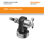
TS20 probe system
© 2002 Renishaw. All rights reserved.
Disclaimer
Renishaw® is a registered trademark of
Renishaw plc.
Considerable effort has been made to ensure
that the contents of this document are free
from inaccuracies and omissions. However,
Renishaw makes no warranties with respect
to the contents of this document and
specifically disclaims any implied warranties.
Renishaw reserves the right to make changes
to this document and to the product described
herein without obligation to notify any person
of such changes.
This document may not be copied or
reproduced in whole or in part, or transferred
to any other media or language, by any
means, without the prior written permission
of Renishaw.
The publication of material within this
document does not imply freedom from
the patent rights of Renishaw plc.
Trademarks
All brand names and product names used in
this document are trade names, service
marks, trademarks, or registered trademarks
of their respective owners.
Renishaw part no: H-2000-5010-12-B
Issued: 09.2002
1-0
Installation and user's guide
TS20 tool setting probe
English
2-0
Guide d'installation et d'utilisation
Palpeur outil TS20
Français
3-0
Installations- und Benutzerhandbuch
Messtaster zur Werkzeugvermessung TS20
Deutsch
4-0
Italiano
Guida per l'installazione e per l'utente
Sonda di Predisposizione Utensili TS20
S2
GB
FCC DECLARATION (USA)
FCC Section 15.19
This device complies with Part 15 of the FCC rules.
Operation is subject to the following two conditions:
1. This device may not cause harmfull interference.
2. This device must accept any interference received,
including interference that may cause undesired
operation.
FCC Section 15.105
This equipment has been tested and found to comply
with the limits for a Class A digital device, pursuant to
Part 15 of the FCC rules. These limits are designed to
provide reasonable protection against harmful
interference when the equipment is operated in a
commercial environment.
This equipment generates, uses, and can radiate radio
frequency energy and, if not installed and used in
accordance with the instruction manual, may cause
harmful interference to radio communications.
Operation of this equipment in a residential area is likely
to cause harmful interference, in which case you will be
required to correct the interference at your own expense.
FCC Section 15.21
The user is cautioned that any changes or modifications
not expressly approved by Renishaw plc, or authorised
representative could void the user's authority to operate
the equipment.
FCC Section 15.27
The user is also cautioned that any peripheral device
installed with this equipment such as a computer, must
be connected with a high-quality shielded cable to insure
compliance with FCC limits.
SAFETY
Information for the user
Beware of unexpected movement. The user should
remain outside of the full working envelope of probe
head/extension/probe combinations.
In all applications involving the use of machine tools
or CMMs, eye protection is recommended.
Remove power before performing any maintenance
operations.
Refer to the machine supplier's operating
instructions.
Information for the machine supplier
It is the machine supplier's responsibility to ensure
that the user is made aware of any hazards
involved in operation, including those mentioned
in Renishaw product documentation, and to
ensure that adequate guards and safety interlocks
are provided.
Under certain circumstances the probe signal may
falsely indicate a probe seated condition. Do not rely
on probe signals to stop machine movement.
S3
D
SICHERHEITSANWEISUNG
Informationen für den Benutzer
Auf unerwartete Bewegungen achten. Der
Anwender sollte sich möglichst nur außerhalb
des Messtaster-Arbeitsbereiches aufhalten.
DK
SIKKERHED
Oplysninger til brugeren
Pas på uventede bevægelser. Brugeren bør holde
sig uden for hele sondehovedets/forlængerens/
sondens arbejdsområde.
Bei Arbeiten an Werkzeugmaschinen oder
Koordinatenmessgeräten wird Augenschutz
empfohlen.
I alle tilfælde, hvor der anvendes værktøjs- og
koordinatmålemaskiner, anbefales det at bære
øjenbeskyttelse.
Vor Wartungsarbeiten muss die
Stromversorgung getrennt werden.
Afbryd strømforsyningen, før der foretages
vedligeholdelse.
Achten Sie auf die Bedienungsanleitungen
des Maschinenherstellers.
Se maskinleverandørens brugervejledning.
Information für den Maschinenlieferanten
Es obliegt dem Maschinenlieferanten, den
Anwender über alle Gefahren, die sich aus
dem Betrieb der Ausrüstung, einschließlich der,
die in der Renishaw Produktdokumentation
erwähnt sind, zu unterrichten und zu versichern,
dass ausreichende Sicherheitsvorrichtungen
und Verriegelungen eingebaut sind.
Unter gewissen Umständen kann der Messtaster
fälschlicherweise zurückgesetzt anzeigen.
Verlassen sie sich nicht auf das Messtastersignal
um die Maschine zu stoppen. Renishaw-Produkte
im Notfall durch Trennen der Stromversorgung
stoppen.
Oplysninger til maskinleverandøren
Det er maskinleverandørens ansvar at sikre,
at brugeren er bekendt med eventuelle risici i
forbindelse med driften, herunder de risici,
som er nævnt i Renishaws produktdokumentation,
og at sikre, at der er tilstrækkelig afskærmning og
sikkerhedsblokeringer.
Under visse omstændigheder kan sondesignalet
ved en fejl angive, at sonden står stille.
Stol ikke på, at sondesignaler stopper maskinens
bevægelse.
S4
E
SEGURIDAD
Información para el usuario
Tener cuidado con los movimientos inesperados.
El usuario debe quedarse fuera del grupo operativo
completo compuesto por la cabeza de sonda/
extensión/sonda o cualquier combinación de las
mismas.
Se recomienda usar protección para los ojos en
todas las aplicaciones que implican el uso de
máquinas herramientas y máquinas de medición
de coordenadas.
Quitar la corriente antes de emprender cualquier
operación de mantenimiento.
Remitirse a las instrucciones de manejo del
proveedor de la máquina.
Información para el proveedor de la máquina
Corresponde al proveedor de la máquina asegurar
que el usuario esté consciente de cualquier peligro
que implica el manejo de la máquina, incluyendo
los que se mencionan en la documentación sobre
los productos Renishaw y le corresponde también
asegurarse de proporcionar dispositivos de
protección y dispositivos de bloqueo de seguridad
adecuados.
Bajo determinadas circunstancias la señal de la
sonda puede indicar erroneamente que la sonda
está asentada. No fiarse de las señales de la sonda
para parar el movimiento de la máquina.
F
SECURITE
Informations à l’attention de l’utilisateur
Attention aux mouvements brusques. L'utilisateur
doit toujours rester en dehors de la zone de sécurité
des installations multiples Tête de Palpeur/Rallonge/
Palpeur.
Le port de lunettes de protection est recommandé
pour toute application sur machine-outil et MMC.
Mettre la machine hors tension avant d'entreprendre
toute opération de maintenance.
Consulter le mode d’emploi du fournisseur de la
machine.
Informations à l’attention du fournisseur de la
machine
Il incombe au fournisseur de la machine d’assurer
que l’utilisateur prenne connaissance des dangers
d'exploitation, y compris ceux décrits dans la
documentation du produit Renishaw, et d'assurer
que des protections et verrouillages de sûreté
adéquats soient prévus.
Dans certains cas, il est possible que le signal du
palpeur indique à tort l'état que le palpeur est au
repos. Ne pas se fier aux signaux du palpeur qui
ne garantissent pas toujours l’arrêt de la machine.
S5
FIN
TURVALLISUUTTA
Käyttäjälle tarkoitettuja tietoja
Varo äkillistä liikettä. Käyttäjän tulee pysytellä
täysin anturin pään/jatkeen/anturin yhdistelmiä
suojaavan toimivan kotelon ulkopuolella.
Kaikkia työstökoneita ja koordinoituja mittauskoneita
(CMM) käytettäessä suositamme silmäsuojuksia.
Kytke pois sähköverkosta ennen huoltotoimenpiteitä.
Katso koneen toimittajalle tarkoitettuja käyttöhjeita.
Tietoja koneen toimittajalle
Koneen toimittaja on velvollinen selittämään
käyttäjälle mahdolliset käyttöön liittyvät vaarat,
mukaan lukien Renishaw’n tuoteselosteessa
mainitut vaarat. Toimittajan tulee myös varmistaa,
että toimitus sisältää riittävän määrän suojia ja lukkoja.
Tietyissä olosuhteissa anturimerkki saattaa osoittaa
virheellisesti, että kyseessä on anturiin liittyvä
ongelma. Älä luota anturimerkkeihin koneen liikkeen
pysäyttämiseksi.
GR
S6
I
SICUREZZA
Informazioni per l’utente
Fare attenzione ai movimenti inaspettati.
Si raccomanda all'utente di tenersi al di fuori
dell’involucro operativo della testina della
sonda, prolunghe e altre varianti della sonda.
Si raccomanda di indossare occhiali di protezione
in applicazioni che comportano macchine utensili
e macchine per misurare a coordinate.
Prima di effettuare qualsiasi intervento di
manutenzione, isolare dall’alimentazione di rete.
Consultare le istruzioni d’uso del fabbricante della
macchina.
Informazioni per il fabbricante della macchina
Il fornitore della macchina ha la responsabilità
di avvertire l'utente dei pericoli inerenti al
funzionamento della stessa, compresi quelli
riportati nelle istruzioni della Renishaw, e di
mettere a disposizione i ripari di sicurezza e
gli interruttori di esclusione.
È possibile, in certe situazioni, che la sonda
emetta erroneamente un segnale che la sonda è in
posizione. Evitare di fare affidamento sugli impulsi
trasmessi dalla sonda per arrestare la macchina.
NL
VEILIGHEID
Informatie voor de Gebruiker
Oppassen voor onverwachte beweging. De gebruiker
dient buiten het werkende signaalveld van de
Sondekop/Extensie/Sonde combinaties te blijven.
Het dragen van oogbescherming wordt tijdens
gebruik van Machinewerktuigen en CMM’s
aanbevolen.
Voordat u enig onderhoud verricht dient u de
stroom uit te schakelen.
De bedieningsinstructies van de machineleverancier
raadplegen.
Informatie voor de Machineleverancier
De leverancier van de machine is
ervoorverantwoordelijk dat de gebruiker op de
hoogte wordt gesteld van de risico’s die verbonden
zijn aan bediening, waaronder de risico’s die vermeld
worden in de produktendocumentatie van Renishaw.
De leverancier dient er tevens voor te zorgen dat de
gebruiker is voorzien van voldoende beveiligingen en
veiligheidsgrendelinrichtingen.
Onder bepaalde omstandigheden kan het
sondesignaal een onjuiste sondetoestand aangeven.
Vertrouw niet op de sondesignalen voor het
stoppen van de machinebeweging.
P
SEGURANÇA
Informações para o Utilizador
Tomar cuidado com movimento inesperado.
O utilizador deve permanecer fora do perímetro
da área de trabalho das combinações Cabeça da
Sonda/Extensão/ Sonda.
Em todas as aplicações que envolvam a utilização
de Máquinas-Ferramenta e CMMs, recomenda-se
usar protecção para os olhos.
Desligar a alimentação antes de efectuar qualquer
operação de manutenção.
Consultar as instruções de funcionamento do
fornecedor da máquina.
Informações para o Fornecedor da Máquina
È responsabilidade do fornecedor da máquina
assegurar que o utilizador é consciencializado de
quaisquer perigos envolvidos na operação,
incluindo os mencionados na documentação do
produto Renishaw e assegurar que são fornecidos
resguardose interbloqueios de segurança
adequados.
Em certas circunstâncias, o sinal da sonda pode
ndicar falsamente uma condição de sonda
assentada. Não confiar em sinais da sonda para
parar o movimento da máquina.
SW
SÅKERHET
Information för användaren
Se upp för plötsliga rörelser. Användaren bör
befinna sig utanför arbetsområdet för sondhuvudet/
förlängningen/sond-kombinationerna.
Ögonskydd rekommenderas för alla tillämpningar
som involverar bruket av maskinverktyg och CMM.
Koppla bort strömmen innan underhåll utförs.
Se maskintillverkarens bruksanvisning.
Information för maskinleverantören
Maskinleverantören ansvarar för att användaren
informeras om de risker som drift innebär,
inklusive de som nämns i Renishaws
produktdokumentation, samt att tillräckligt goda
skydd och säkerhetsförreglingar tillhandahålls.
Under vissa omständigheter kan sondens signal
falskt ange att en sond är monterad.
Lita ej på sondsignaler för att stoppa maskinens
rörelse.
S7
Installation and user’s guide - English
Contents
TS20 probe
…
…
1-1
Probe signal processing options
…
1-2
Cable options
…
…
…
1-4
Installation
…
…
…
1-5
Specification
…
…
…
1-6
Signal conditioning module
…
1-8
Electrical specification
…
…
1-10
Stylus fitting instructions …
…
1-12
Parts list
…
1-13
…
…
…
WARRANTY
Equipment requiring attention under warranty
must be returned to your supplier. No claims
will be considered where Renishaw equipment
has been misused, or repairs or adjustments
have been attempted by unauthorised persons.
CHANGES TO EQUIPMENT
Renishaw reserves the right to change
specifications without notice.
CNC MACHINE
CNC machine tools must always be operated
by competent persons in accordance with
manufacturers instructions.
CARE OF THE PROBE SYSTEM
Keep components reasonably clean.
PATENT NOTICE
Features of products shown in this user guide,
and of related products, are the subject of the
following patents and patent applications:
DE
EP
EP
EP
EP
4413968
0293036
0695926
0748669
1051668
GB
IT
JP
JP
JP
2277593
1273643
1,445/1997
2,098,080
320,394/1994
US
US
US
WO
5,446,970
5,647,137
5,669,151
00/33149
1-1
TS20 PROBE
HPA
Stylus
TS20
Automatic arm
TS20 with automatic arm
The TS20 is a two axis tool setting probe, used on
CNC lathes.
During a tool setting routine, each turret mounted
tool is driven against the square tip stylus. When
contact is made, a trigger signal is generated and
tool offsets are automatically recorded in the
machine control registers.
There are three versions of the TS20 probe,
for 24 mm, 32 mm or 40 mm tooling respectively.
TS20
TS20 with high precision arm (HPA)
The probe may be mounted on an automatic
arm which is retracted out of the machines
working envelope when the probe is not in use.
Alternatively the probe may be mounted on a
Renishaw high precision manual arm (HPA).
A quick release mounting enables the HPA to
be easily removed from the machine when the
probe is not required.
During installation the probe stylus tip may be
set to align with the machine X or Y axes.
1-2
PROBE - SIGNAL PROCESSING OPTIONS
PROBE SIGNAL PROCESSING
A signal conditioning module (SCM) or interface unit (MI 5 or MI 8 or MI8-4)
is required to process signals between the probe and CNC machine control.
Probe
TS20 mounted on high precision arm (HPA)
with signal conditioning module (SCM)
The SCM located within the HPA,
provides an OCT output.
HPA
▼
CNC
machine
control
OCT
output
SCM
TS20 mounted on high precision arm (HPA)
with signal conditioning module (SCM)
and SSR convertor
When SSR output is required, an SSR convertor is used to convert
the OCT output from the SCM, to voltage free SSR output.
Probe
HPA
SSR
output
SSR
convertor
▼
▼
CNC
machine
control
OCT
output
SCM
1-3
PROBE - SIGNAL PROCESSING OPTIONS
TS20 mounted on an automatic arm
with MI 5 or MI 8 or MI 8-4 interface
MI 8 interface
The MI 8 provides voltage free solid state relay
(SSR) output, configurable for either normally
open (NO) or normally closed (NC).
The MI 8-4 interface accepts the probe
output signal from the MI 12 interface.
The user can then select between
inspection or tool setting probe outputs
by selecting an ‘M’ code.
An inhibit input enables an optical transmission
type inspection probe and interface to be used,
on the same machine input as the TS20.
MI 5 interface
Where an inspection probe with inductive
transmission is used on the same machine
as the TS20, a single MI 5 interface is
recommended, as it can accept both
the inspection probe (inductive) and TS20
tool setting probe (hard wired) inputs.
MI 8-4 interface
Where an inspection probe with optical
transmission and an MI 12 interface,
are used on the same machine as the TS20,
the MI 8-4 interface is recommended.
SSR
output
MI 8
or
MI 8-4
or
MI 5
interface
▼
▼
CNC
machine
control
IMPORTANT
The signal conditioning module
is NOT used with arrangement
1-4
PROBE - CABLE OPTIONS
❑
Cable is four core 7/0,2 polyurethane insulated and screened. Cable diameter 4,4 mm (0.17 in).
Probe circuit - red and blue cores (yellow and green are not used).
❑
Ensure the probe cable is routed away from other cables carrying high currents.
TS20 probe with cable
TS20 probe with
straight stylus
5000 mm (16.4 ft)
TS20 probe with cable and Lemo connector
350 mm (13.8 in)
TS20 probe with
cranked stylus
Lemo connector
TS20 probe with cable and signal conditioning module (SCM)
3360 mm (11 ft)
Signal conditioning module
INSTALLATION
SAFETY
The TS20 system must be installed by a competent person
observing relevant safety precautions.
Before commencing work, ensure the machine tool is in a safe
condition with the power switched OFF.
Switch off the power supply to the TS20 probe system components.
CABLE FROM PROBE
Ensure the probe cable is routed away from
other cables carrying high currents.
PROBE FALSE TRIGGER
The TS20-SCM should be installed on machines
with a stable power supply i.e. Interference free.
If false triggers occur, investigate the power
supply rails for interference.
ELECTRICAL INTERFERENCE
It is recommended that the SSR convertor
or interface unit is installed within the
machine electronics control cabinet.
PROBE STATUS
TS20 styli have an M3 thread and 10 x 10 mm tip.
Straight styli incorporate a break stem to protect
the probe in the event of a collision. A damaged
stylus can be replaced - see page 1-12.
TS20 probe with straight stylus
When a replacement stylus is fitted, the stylus
squareness specification cannot be guaranteed,
after the original stylus has been removed.
Normal electronic equipment installation
rules apply.
TS20 probe with cranked stylus
When a replacement styli is fitted, the stylus
squareness and parallelism specification cannot
be guaranteed, once the original stylus has been
removed.
i.e. Units should be mounted away from
any potential sources of interference,
such as three phase transformers and
motor controllers.
SOFTWARE ROUTINES
Toolsetting software routines to suit various
machine controllers are available from Renishaw
(the current list is available on application).
1-5
1-6
TS20 SPECIFICATION
Normally ±X and ±Z axes
of a lathe
Uni-directional
repeatability.
Maximum mean
σ) value
2 sigma (2σ
2 µm (0.00008 in)
Valid for test velocity of
480 mm/min (1.57 ft/min)
at stylus tip
Temperature limits
Operating
Storage
0,02 mm (0.00079 in)
Sense directions
Non probing direction
A
Probe X and Y
overtravel with
straight stylus
B
TS20 PROBE with STRAIGHT STYLUS
5° to 60° C (41° to 140° F)
–13° to 60° C (9° to 140° F)
Tooling
size
Dimension A
also shown on
page 1-9
Dimension B
also shown
on page 1-9
Stylus
overtravel
with
straight styli
Uni-directional
σ
repeatability 2σ
At a probing speed of
480 mm/min (1.57 ft/min)
25 mm
(0.98 in)
41 mm
(1.61 in)
28,25 mm
(1.11 in)
±6 mm
(±0.24 in)
2,0 µm
(0.00008 in)
0,60 - 1,6 N
60 - 160 gf
(2.12 - 5.64 ozf)
32 mm
(1.26 in)
50 mm
(1.96 in)
37,25 mm
(1.46 in)
±7,5 mm
(±0.30 in)
2,5 µm
(0.0001 in)
0,47 - 1,26 N
47 - 126 gf
(1.66 - 4.44 ozf)
40 mm
(1.57 in)
58 mm
(2.28 in)
45,25 mm
(1.78 in)
±9 mm
(±0.35 in)
3,0 µm
(0.00012 in)
0,39 - 1,6 N
39 - 106 gf
(1.38 - 3.74 ozf)
Trigger force
dependant on
sense direction
1-7
TS20 SPECIFICATION
TS20 PROBE with CRANKED STYLUS for applications where the straight stylus is not suitable
0,02 mm (0.0008 in)
in Z direction
A
0,03 mm (0.0012 in)
in X direction
A
Non probing direction
OVERTRAVEL
Do not exceed the quoted overtravel distance for each
direction, otherwise the tool tip may slip off the stylus
edge, and could cause damage to the probe.
A
39 mm (1.53 in)
❃
❃
A
B
C
D
34 mm
(1.34 in)
σ
Uni-directional repeatability 2σ
At a probing speed of 480 mm/min (1.57 ft/min)
Note:
The characteristics of cranked styli do not
allow them to have as good a repeatability
performance as straight styli
2 µm
(0.00008 in)
❃
Trigger force
(dependant on
sense direction)
0,6 - 1,6 N
60 - 160 gf
(2.12 - 5.64 ozf)
Direction
Overtravel
A
3,0 mm (0.12 in)
B
3.0 mm (0.12 in)
C
1,2 mm (0.05 in)
D
2,3 mm (0.09 in)
1-8
TS20 PROBE with SIGNAL CONDITIONING MODULE
dimensions mm (in)
'O' ring supplied may be fitted in
groove to seal probe mounting
Recommended 'O' ring dimensions
3
Ø1 x 18,1 ID (Ø0.039 x 0.71 ID)
(0.12)
Alignment of the stylus with
the machine X and Z axes is
obtained by slackening the
four M3 x 8 mm clamping
screws and rotating the
probe body.
Ø
Stylus alignment
in X and Z axes
▲
0,5 x 45°
(0.02 x 45°)
R 0,5 MAX
(R 0.02 MAX)
When alignment is achieved,
tighten the clamping screws.
Signal conditioning module
2950 (116)
32 (1.26)
Ø8 (Ø0.32)
47 (1.85)
Ø15 (0.59)
MINIMUM clearance
32 (1.26)
19,55 (0.770)
19,45 (0.766)
18,2 (0.717)
17,9 (0.705)
1,6µm
(63µin)
Ø
1,6 (0.063)
1,5 (0.059)
Clamping
screws
1-9
TS20 PROBE with SIGNAL CONDITIONING MODULE
dimensions mm (in)
Four tip faces
mutually
I or // to 6 µm
(0.00024 in)
10 (0.39) square
Straight or cranked styli
A - see page 1-6
7,9 (0.31)
7,35 (0.29)
B - see page 1-6
0,8µm
(32µin) Ø 17,85 (0.703)
17,75 (0.699)
4 (0.16)
Ø17,4 (Ø0.69)
Clamping ring
Clamps the probe in its desired position
3,1 (0.12)
Ø29,5
(Ø1.16)
Four holes
Ø3,3 (Ø0.13).
Equi-spaced on
Ø23,5 PC (0.925)
Ø
14,95 (0.589)
14,85 (0.585)
Spacer
Provides a secure seating face
when installing the probe
0,02 (0.00079)
20,7 (0.82)
19,3 (0.76)
295
(11.6)
Ø4,4 MAX
(Ø0.173 MAX)
1-10
ELECTRICAL SPECIFICATION
TS20 with signal conditioning module (SCM)
The TS20 probe is designed to be used wIth a load resistor.
Minimum load resistor at 30 V
Maximum supply voltage 30 V
Minimum supply voltage 9 V
Cable
Four core 7/0,2 polyurethane insulated
and screened cable.
Probe circuit - red and blue cores,
(yellow and green are not used).
1K2 Ohms
Maximum current 25 mA - probe seated
Minimum current 2 mA - probe seated
The load resistor is connected in either
positive or negative lead (see opposite).
It can be any value that does not cause the
circuit to exceed the max/min current ratings.
The probe is protected against reverse voltage
within the specified ratings.
Electrical characteristics at 20° C (68° F)
Minimum
Stand-by current
(probe deflected)
Voltage drop across output leads
(probe seated)
Load current 25mA
5mA
2mA
Output pulse length when
probe deflects (trigger)
20.0 mS
Typical
Maximum
320 µA
500 µA
4.5 V
3.5 V
2.8 V
5.2 V
3.9 V
3.1 V
1-11
ELECTRICAL SPECIFICATION
TS20 with signal conditioning module (SCM)
Typical performance with 4K7 load resistor and 24 V supply
B - Resistance in negative lead
A - Resistance in positive lead
Probe
4K7
Load resistor
Red
Blue
Signal
Conditioning
Module
Probe
+24 V
Signal
Conditioning
Module
Vo
(output)
Red
0V
●
Screen
Blue
4K7
Load resistor
Ground
+24 V
Vo
(output)
0V
Screen
Ground
A - Resistance in positive lead
PROBE
Minimum
Typical
Output voltage (Vo)
(probe seated)
Output voltage (Vo)
(probe deflected)
21.7 V
22.5 V
B - Resistance in negative lead
Maximum
Minimum
Typical
3.9 V
20.1 V
20.5 V
1.5 V
Maximum
2.3 V
1-12
STYLUS FITTING INSTRUCTIONS
The stylus break stem protects the probe in the event of a collision.
Stylus
tip
Broken
break
stem
Stylus tip
with
break stem
Hexagon key
torque
2,5 Nm (1.85 lbf.ft)
Hexagon key
Fitting stylus
onto
probe
Fitting stylus tip
onto
new break stem
Recover stylus tip
from
broken break stem
Spanner
Apply to lower flats
torque
1,2 Nm (0.88 lbf.ft)
Countersunk
screw
Spanner
Apply to upper flats
To recover stylus tip from a
broken stem, use spanner
on upper flats of stem.
Break
stem
Tommy bar
Spanner
Apply to upper flats
Before fitting stylus tip onto new
stem, apply Loctite 242 to thread
of countersunk screw. Use
spanner on upper flats of stem.
When fitting stylus to probe,
support mounting with
tommy bar and use spanner
on lower flats of stem.
BREAK STEM - Please quote the part no. when ordering a replacement stem
Application
Break stem
part no.
Application
Break stem
part no.
Application
Break stem
part no.
25 mm (tooling)
M-2008-0333
32 mm (tooling)
M-2008-0604
40 mm (tooling)
M-2008-0605
PARTS LIST - please quote the part number when ordering equipment
TS20 PROBE with STRAIGHT STYLUS
Part no. and Description
TS20 probe
with cable
and
MI 8 interface
TS20 probe
with
SCM
TS20 probe
with SCM
and
SSR convertor
A-2008-0151
A-2008-0270
A-2008-0002
A-2008-0269
32 mm
(1.26 in)
A-2008-0123
A-2008-0274
A-2008-0183
A-2008-0273
40 mm
(1.57 in)
A-2008-0277
A-2008-0278
A-2008-0285
A-2008-0276
Tooling
size
TS20 probe
with
cable
25 mm
(0.98 in)
Part no. and Description
Tooling
size
TS20 probe
with
Lemo
connector
TS20 probe
with
Lemo connector
and
MI 8 interface
25 mm
(0.98 in)
A-2048-0500
A-2008-0272
32 mm
(1.26 in)
A-2008-0110
A-2008-0275
40 mm
(1.57 in)
A-2008-0121
A-2008-0279
1-13
1-14
PARTS LIST - please quote the part number when ordering equipment
TS20 PROBE with CRANKED STYLUS
Part no. and Description
TS20 probe
with
cable
TS20 probe
with cable
and
MI 8 interface
TS20 probe
with
SCM
TS20 probe
with SCM
and
SSR convertor
A-2008-0281
A-2008-0282
A-2008-0284
A-2008-0280
TS20 probe
with
Lemo connector
A-2048-0262
TS20 probe
with
Lemo connector
and
MI 8 interface
A-2008-0283
ASSOCIATED EQUIPMENT
Type
Part no.
Description
SSR convertor
A-2023-0010
SSR convertor with mounting supports and feet.
MI 8
A-2073-0010
MI 8 interface with mounting supports and feet.
MI 8 / DIN
A-2073-0020
MI 8 interface with DIN rail mounting.
MI 8-4
A-2157-0001
MI 8-4 interface with DIN rail mount and dual lock pads.
MI 5
A-2019-0006
MI 5 interface
MI 12
A-2075-0142
MI 12 interface
PARTS LIST - please quote the part number when ordering equipment
STYLI for TS20
Please refer to instructions page 1-12
Type
Part no.
Description
25 mm (tooling)
A-2008-0601
Straight stylus with square tip stylus 10 x 10 mm (0.39 x 0.39 in).
32 mm (tooling)
A-2008-0602
Straight stylus with square tip stylus 10 x 10 mm (0.39 x 0.39 in).
40 mm (tooling)
A-2008-0603
Straight stylus with square tip stylus 10 x 10 mm (0.39 x 0.39 in).
Cranked
A-2008-0249
Cranked stylus with square tip stylus 10 x 10 mm (0.39 x 0.39 in).
ASSOCIATED SYSTEM USERS GUIDES
Part no.
H-2000-5011
Description
SSR convertor
H-2000-5015
MI 8 interface
H-2000-5008
MI 8-4 interface
H-2000-5014
MI 5 interface
H-2000-5073
MI 12 interface
1-15
Guide d’installation et d’utilisation - Français
Table des matières
Applications du palpeur
…
…
2-1
Options de traitement des signaux
…
2-2
Options de cables
…
…
2-4
Installation
…
…
…
2-5
Spécifications
…
…
…
2-6
Module de mise en forme du signal
Spécification électrique
…
2-8
…
2-10
Instructions de mise en place du stylet
2-12
Liste des pièces détachées
2-13
…
GARANTIE
Tout équipement nécessitant un contrôle sous
garantie doit être retourné au fournisseur.
Aucune réclamation ne sera prise en compte
pour toute mauvaise utilisation du matériel
Renishaw, ou suite à toute réparation ou tout
réglage effectués par des personnes non agréées.
CHANGEMENTS DE SPECIFICATION DU MATERIEL
Renishaw se réserve le droit de modifier les
spécifications sans avis préalable.
MACHINE CNC
L’utilisation des machines-outils CNC est
exclusivement réservée au personnel compétent
conformément aux instructions du constructeur.
SOIN DU SYSTEME DE PALPAGE
S’assurer que les composants sont propres.
NOTE CONCERNANT LES BREVETS:
Les produits décrits dans ce guide utilisateur et leurs
applications sont protégés par les brevets suivants.
DE
EP
EP
EP
EP
4413968
0293036
0695926
0748669
1051668
GB
IT
JP
JP
JP
2277593
1273643
1,445/1997
2,098,080
320,394/1994
US
US
US
WO
5,446,970
5,647,137
5,669,151
00/33149
2-1
APPLICATIONS DU PALPEUR
HPA
Stylet
TS20
Bras automatique
TS20 avec bras automatique
Le palpeur TS20 est un palpeur outil 2 axes
utilisé pour les réglages d’outil sur tours CNC.
Au cours d’une routine de réglage d’outil,
chaque outil monté sur tourelle se place contre
le stylet à pointe carrée. Lorsqu’il y a contact,
un signal de déclenchement se produit et des
décalages d’outil sont automatiquement stockés
dans les registres de commande de la machine.
Il existe trois versions du palpeur TS20 : le palpeur
pour outillage 25 mm, 32 mm ou 40 mm.
TS20
TS20 avec bras de haute précision (HPA)
Le palpeur peut être monté sur un bras
automatique retiré de l’enveloppe de travail de
la machine lorsque le palpeur n’est pas utilisé.
Le palpeur peut également être monté sur un
bras manuel haute précision Renishaw (HPA).
Un montage à dégagement rapide permet de
retirer facilement le HPA de la machine lorsque
le palpeur n’est pas nécessaire.
Lors de l’installation, la pointe du stylet du
palpeur peut être réglée de façon à s’aligner
avec les axes X ou Z de la machine.
2-2
PALPEUR - OPTIONS DE TRAITEMENT DES SIGNAUX
TRAITEMENT DES SIGNAUX DU PALPEUR
On utilise un Module de mise en forme du signal (SCM) ou une unité d’interface (MI 5 ou MI 8 ou MI 8-4)
pour traiter les signaux transmis entre le palpeur et l’unité de commande de la machine CNC.
Palpeur
TS20 avec bras de haute précision (HPA)
et module de mise en forme du signal (SCM)
Le module de conditionnement “SCM”
situé dans le HPA délivreun signal sur
“Collecteur ouvert” (OCT)
HPA
▼
Unité de
commande
de machine
CNC
Sortie
OCT
SCM
TS20 avec bras de haute précision
et SCM + Convertisseur SSR
Lorsqu’une sortie SSR est nécessaire, on utilise
un convertisseur SSR pour convertir la sortie OCT
du SCM en sortie SSR sans voltage.
Palpeur
HPA
Sortie
SSR
Convertisseur
SSR
▼
▼
Unité de
commande
de machine
CNC
Sortie
OCT
SCM
PALPEUR - OPTIONS DE TRAITEMENT DES SIGNAUX
TS20 avec bras automatique et
interface MI 5 ou MI 8 ou MI 8-4
Interface MI 8
L’interface MI 8 fournit une sortie de relais
statique (SSR) sans voltage que l’on peut
configurer sur Normalement ouvert (N/O)
ou Normalement fermé (N/F).
machine, l’utilisation d’une interface
MI 8-4 est recommandée.
L’interface MI 8-4 reçevant les signaux de
palpage provenant du TS20 et de la MI 12,
l’utilisateur peut choisir le type de palpage
désiré en activant une fonction “Code M”
Les entrées inhibitions permettent d’utiliser
une interface et un palpeur d’inspection de
type transmission optique sur la même
entrée machine que le TS20.
Interface MI 5
Pour l’utilisation d’un palpeur d’inspection à
transmission inductive sur la même machine
que le TS20, seule une interface MI 5 est
recommandée car celle-ci accepte aussi bien
les entrées de palpeur d’inspection (inductif)
que les entrées de palpeur outil TS20 (câblé).
Interface MI 8-4
Quand un système de palpage pièce à
transmission optique avec interface MI 12
et un capteur TS20 sont montés sur la même
Sortie
SSR
Interface
MI 8
ou
MI 8-4
ou
MI 5
▼
▼
Unité de
commande
de machine
CNC
IMPORTANT
Le module de mise en forme
du signal N’EST PAS utilisé
pour cette disposition
2-3
2-4
PALPEUR - OPTIONS DE CABLES
❑
Câble antiparasité à quatre conducteurs avec isolation polyuréthanne 7/0,2.
Câble de 4,4 mm de diamètre.
Circuit palpeur : conducteurs rouge et bleu (le jaune et le vert ne sont pas utilisés).
❑
S’assurer que le câble du palpeur ne passe pas près des autres câbles à fort courant.
Palpeur TS20 à câble
Palpeur TS20
à stylet droit
5000 mm
Palpeur TS20 à câble et connecteur Lemo
350 mm
Palpeur TS20
à stylet coudé
Connecteur Lemo
Palpeur TS20 à câble et module de mise en forme du signal (SCM)
3360 mm
Module de mise en forme du signal
INSTALLATION
SECURITE
Le système TS20 doit être installé par une personne compétente
respectant les consignes de sécurité s’y rapportant.
Avant de procéder à toute opération, s’assurer que la machine-outil
dans un état sûr et qu’elle est HORS TENSION.
Mettre les composants du système de palpage TS20 hors tension.
CABLE DU PALPEUR
S’assurer que le câble du palpeur ne passe pas
près des autres câbles à fort courant.
MAUVAIS DECLENCHEMENT DU PALPEUR
Le palpeur TS20-SCM doit être installé sur les
machines à alimentation électrique stable,
c’est-à-dire sans interférence. En cas de mauvais
déclenchement, vérifier s’il existe des interférences
sur les pôles de l’alimentation électrique.
INTERFERENCE ELECTRIQUE
Il est recommandé d’installer le convertisseur SSR
ou l’unité d’interface dans l’armoire de commande
des composants électroniques de la machine.
Les règles d’installation de matériel électronique
normales sont en vigueur :
Les unités ne doivent pas être montées près
de sources potentielles d’interférences telles
que les transformateurs triphasiques et les
contrôleurs moteur.
STYLET DU PALPEUR
Les stylets TS20 possèdent un filet M3 et une pointe
de 10 x 10 mm.
Les stylets droits ont une tige de rupture destinée à
protéger le palpeur en cas de collision. Il est possible
de remplacer un stylet endommagé (voir page 2-12).
Palpeur TS20 à stylet droit
Il n’est pas possible de garantir la spécification carrée
du stylet lors de l’installation du stylet de remplacement,
une fois que le stylet d’origine est retiré.
Palpeur TS20 à stylet coudé
Il n’est pas possible de garantir la spécification carrée
du stylet lors de l’installation des stylets de
remplacement, une fois que le stylet d’origine est retiré.
ROUTINES DE LOGICIEL
Des routines de logiciel de réglage d’outil adaptées
à différentes unités de commande de machine sont
disponibles auprès de Renishaw
(la liste est disponible sur demande).
2-5
2-6
SPECIFICATION POUR LE TS20
Axes ±X et ±Y d’un tour,
normalement
Répétabilité
unidirectionnelle.
σ)
Valeur 2 Sigma (2σ
Moyenne maximale
2 µm
Valide pour une vitesse
test de 480 mm/min à
la pointe du stylet
Limites de température
Fonctionnement
Stockage
de
5° à 60° C
de –13° à 60° C
A
B
B
Directions de palpage
Sens de non-palpage
0,02 mm
Surcourse X et Y
du palpeur à
stylet droit
PALPEUR TS20 à STYLET DROIT
Force de
déclenchement
(dépend de la
direction de
palpage)
Taille de
l’outillage
Dimension A
Indiquée à la
page 2-9
également
Dimension B
Indiquée à la
page 2-9
également
Surcourse
du palpeur
à stylet droit
25 mm
41 mm
28,25 mm
±6 mm
2,0 µm
0,60 - 1,6 N
60 - 160 gf
32 mm
50 mm
37,25 mm
±7,5 mm
2,5 µm
0,47 - 1,26 N
47 - 126 gf
40 mm
58 mm
45,25 mm
±9 mm
3,0 µm
0,39 - 1,6 N
39 - 106 gf
Répétabilité
σ
unidirectionnelle 2σ
à une vitesse de palpage
de 480 mm/min
SPECIFICATION TS20
PALPEUR TS20 à STYLET COUDE réservé aux applications pour lesquelles le stylet droit n’est pas approprié
0,02 mm
en sens Z
A
0,03 mm
en sens X
A
Sens de non-palpage
SURCOURSE
Ne pas dépasser la distance de surcourse indiquée
dans chaque direction car la pointe de l’outil risque
de déraper du bord du stylet, et ainsi d’endommager
le palpeur.
A
39 mm
❃
❃
A
B
C
D
34 mm
σ
Répétabilité unidirectionnelle 2σ
A une vitesse de palpage de 480 mm/min
Remarque :
La répétabilité des stylets coudés n’est
pas aussi bonne que celle des stylets
droits du fait de leurs caractéristiques.
2 µm
Force de
déclenchement
(dépend de la direction
de palpage)
0,6 - 1,6 N
60 - 160 gf
❃
Direction
Surcourse
A
3,0 mm
B
3.0 mm
C
1,2 mm
D
2,3 mm
2-7
2-8
On aligne le stylet avec les
axes de la machine X et Z
en desserrant les quatre
vis de fixation M3 x 8 mm
et en faisant tourner le corps
du palpeur.
0,5 x 45°
R 0,5 MAX
Lorsque le tout est aligné,
serrer les vis de fixation.
Module de mise en forme du signal
2950
32
47
Ø15 Dégagement MINIMAL
Ø8
32
18,2
17,9
19,55
19,45
Ø
Alignement du stylet
en axes X et Z
Ø
PALPEUR TS20 à MODULE DE MISE EN FORME DU SIGNAL
dimensions mm
Le joint torique fourni peut
être placé dans la rainure afin
de sceller le montage palpeur
Dimensions de joint torique
3
recommandées
1,6
Ø 1 x 18,1 ID
1,5
Vis de
1,6 µm
fixation
2-9
PALPEUR TS20 à MODULE DE MISE EN FORME DU SIGNAL
dimensions mm
Quatre faces de
pointe mutuellement
ou
à 6 µm
4
Carré 10
Stylets droits ou coudés
A - voir page 2-6
Ø29,5
Quatre trous
Ø3,3
Équidistants sur
cercle primitif
Ø23,5
7,9
7,35
B - voir page 2-6
0,8 µm Ø
4
Ø
Ø17,4
Bague de serrage
Fixe le palpeur à la position voulue
14,95
14,85
Pièce d’écartement
Fournit une face de repos fixe
lors de l’installation du palpeur
3,1
0,02
17,85
17,75
20,7
19,3
295
Ø4,4 MAX
2-10
SPECIFICATION ELECTRIQUE
TS20 avec module de mise en forme du signal (SCM)
Le palpeur TS20 est conçu pour être utilisé avec une résistance de charge
1K2 Ohms
Résistance de charge minimale à 30 V
Intensité maximale de 25 mA : palpeur au repos
Tension d’alimentation maximale de 30 V
Intensité minimale de 2 mA : palpeur au repos
Tension d’alimentation minimale de 9 V
Câble
Câble antiparasité à quatre conducteurs
avec isolation polyuréthanne 7/0,2.
Circuit palpeur : conducteurs rouge et bleu
(le vert et le jaune en sont pas utilisés).
La résistance de charge est branchée sur le fil positif
ou le fil négatif (voir ci-contre).
Elle peut avoir n’importe quelle valeur pourvu que le
circuit ne dépasse pas les valeurs nominales max/min.
Le palpeur est protégé contre les tensions inverses
dans la gamme des valeurs nominales spécifiées.
Caractéristiques électriques à 20° C Courant d’attente (palpeur dévié)
Minimum
Courant d'attente
(palpeur dévié)
Chute de tension dans les fils de sortie
(palpeur au repos)
Courant de charge 25 mA
5 mA
2 mA
Longueur d’impulsion de sortie lorsque
le palpeur est dévié (Déclenchement)
20,0 mS
Type
Maximum
320 µA
500 µA
4,5 V
3,5 V
2,8 V
5,2 V
3,9 V
3,1 V
2-11
SPECIFICATION ELECTRIQUE
TS20 avec module de mise en forme du signal (SCM)
Performance type avec une résistance de charge 4K7 et une alimentation de 24 V
A-Résistance fil positif
Palpeur
B-Résistance fil négatif
Palpeur
+24 V
4K7
Résistance
de charge
Module de mise
en forme du signal
Rouge Vo
(Sortie)
Bleu
Module de mise
en forme du signal
0V
Rouge
●
Écran
4K7
Résistance
de charge
Terre
Bleu
+24 V
Vo
(Sortie)
0V
Écran
Terre
A-Résistance fil positif
PALPEUR
Minimum
Type
Tension de sortie (Vo)
(palpeur au repos)
Tension de sortie (Vo)
(palpeur dévié)
21,7 V
22,5 V
B-Résistance fil négatif
Maximum
Minimum
Type
3,9 V
20,1 V
20,5 V
1,5 V
Maximum
2,3 V
2-12
INSTRUCTIONS DE MISE EN PLACE DU STYLET
La tige de rupture du stylet protège le palpeur en cas de collision
Récupérer la pointe
du stylet de la tige
de rupture cassée
Clef hexagonale
Mise en place
du stylet
sur le palpeur
Pointe du
stylet avec
tige de rupture
Couple de clef
hexagonale
2,5 Nm
Clef
pour surfaces
plates inférieures
Couple 1,2 Nm
Vis à tête
conique
Pointe du
stylet
Tige de
rupture
cassée
Mise en place de la pointe
du stylet sur la nouvelle
tige de rupture
Clef
pour surfaces plates
supérieures
Pour récupérer la pointe du stylet
de la tige cassée, la dégager en
utilisant une clef sur les surfaces
plates supérieures de la tige.
Tige de
rupture
Broche
lisse
Clef
pour surfaces plates
supérieures
Avant d’installer la pointe du stylet sur
la nouvelle tige, appliquer de la Loctite
242 sur le filet de la vis à tête conique.
Utiliser la clef sur les surfaces plates
supérieures de la tige.
Lors de l’installation du stylet sur
le palpeur, soutenir le montage
avec une broche lisse et utiliser
une clef sur les surfaces plates
inférieures de la tige.
TIGE DE RUPTURE - Veuillez indiquer la référence de la pièce lors de la commande d’une tige de remplacement
Application
Réf. de tige
de rupture
25 mm (outillage) M-2008-0333
Application
Réf. de tige
de rupture
32 mm (outillage) M-2008-0604
Application
Réf. de tige
de rupture
40 mm (outillage) M-2008-0605
2-13
LISTE DES PIECES DETACHEES - Veuillez indiquer la référence de la pièce à la commande
PALPEUR TS20 à STYLET DROIT
Référence de pièce et description
Taille
de
l’outillage
Palpeur
TS20
à câble
Palpeur
TS20
à câble et
interface MI 8
Palpeur
TS20
à SCM
Palpeur
TS20
à SCM et
convertisseur SSR
25 mm
A-2008-0151
A-2008-0270
A-2008-0002
A-2008-0269
32 mm
A-2008-0123
A-2008-0274
A-2008-0183
A-2008-0273
40 mm
A-2008-0277
A-2008-0278
A-2008-0285
A-2008-0276
Référence de pièce et description
Taille
de
l’outillage
Palpeur
TS20
à connecteur
Lemo
Palpeur
TS20
à connecteur
Lemo et
interface MI 8
25 mm
A-2048-0500
A-2008-0272
32 mm
A-2008-0110
A-2008-0275
40 mm
A-2008-0121
A-2008-0279
2-14
LISTE DES PIECES DETACHEES - Veuillez indiquer la référence de la pièce à la commande
PALPEUR TS20 à STYLET COUDÉ
Référence de pièce et description
Palpeur
TS20
à câble
Palpeur
TS20
à câble
et
interface MI 8
Palpeur
TS20
à SCM
Palpeur
TS20
à SCM et
convertisseur
SSR
A-2008-0281
A-2008-0282
A-2008-0284
A-2008-0280
Palpeur
TS20
à connecteur
Lemo
Palpeur
TS20
à connecteur
Lemo
et
interface MI 8
A-2048-0262
A-2008-0283
MATERIELS ANNEXES
Type
Réf. de pièce
Description
Carte convertisseur SSR
A-2023-0010
Carte SSR avec supports de montage et pieds
MI 8
A-2073-0010
Interface MI 8 avec supports de montage et pieds
MI 8 / DIN
A-2073-0020
Interface MI 8 pour montage sur rails DIN
MI 8-4
A-2157-0001
Interface MI 8-4 pour montage sur rails DIN
MI 5
A-2019-0006
Interface MI 5
MI 12
A-2075-0142
Interface MI 12
avec double verrouillage
LISTE DES PIECES DETACHEES - Veuillez indiquer la référence de la pièce à la commande
STYLETS pour TS20
Veuillez vous reporter aux instructions de la page 2-12
Type
Réf. de pièce
Description
25 mm (outillage)
A-2008-0601
Stylet droit avec stylet à pointe carrée 10 x 10 mm
32 mm (outillage)
A-2008-0602
Stylet droit avec stylet à pointe carrée 10 x 10 mm
40 mm (outillage)
A-2008-0603
Stylet droit avec stylet à pointe carrée 10 x 10 mm
Coudé
A-2008-0249
Stylet coudé avec stylet à pointe carrée 10 x 10 mm
GUIDES UTILISATEUR DES SYSTEMES ASSOCIES
Réf. de pièce
Description
H-2000-5011
Convertisseur SSR
H-2000-5015
Interface MI 8
H-2000-5008
Interface MI 8-4
H-2000-5014
Interface MI 5
H-2000-5073
Interface MI 12
2-15
Installations- und Benutzerhandbuch - Deutsch
Inhaltsverzeichnis
Einsatz des Messtasters
…
3-1
Signalverarbeitungsoptionen
…
3-2
Kabeloptionen des Messtasters
…
3-4
Installation
…
…
3-5
…
…
3-6
…
3-8
…
…
3-10
Montage des Tastereinsatzes
…
3-12
Teileliste
…
3-13
…
Technische Daten
…
Signalaufbereitungsmodul
Elektrische Daten
…
…
GARANTIE
Geräte, die während der Garantiezeit Mängel
aufweisen, sind an den Lieferanten
zurückzusenden.
Für ungeeignete oder unsachgemäße
Verwendung, fehlerhafte oder nachlässige
Behandlung durch den Besteller oder Dritte
wird keine Haftung übernommen.
ÄNDERUNGSVORBEHALT
Renishaw behält sich das Recht zur Änderung
technischer Daten ohne Vorankündigung vor.
CNC-MASCHINEN
CNC-Werkzeugmaschinen sollten stets
von Fachleuten gemäß der Anleitung
des Herstellers bedient werden.
PFLEGE DES MESSTASTERSYSTEMS
Die Bauteile sind sauber zu halten.
PATENTHINWEIS
Merkmale und Funktionen der in diesem Handbuch
gezeigten Produkte sind durch nachfolgende
Patente und Patentanmeldungen geschützt:
DE
EP
EP
EP
EP
4413968
0293036
0695926
0748669
1051668
GB
IT
JP
JP
JP
2277593
1273643
1,445/1997
2,098,080
320,394/1994
US
US
US
WO
5,446,970
5,647,137
5,669,151
00/33149
3-1
EINSATZ DES MESSTASTERS
HPA
Tastereinsatz
TS20
Automatischer Arm
TS20 mit automatischem Arm
Der TS20 ist ein Messtaster zur Werkzeugmessung
in 2 Achsen auf CNC-Drehmaschinen.
Zur Werkzeugmessung wird jedes Werkzeug
des Magazines gegen die quadratische Tastplatte
gefahren. Bei Berührung wird ein Schaltsignal
erzeugt und die Werkzeugkompensationen werden
automatisch im Werkzeugkorrekturspeicher
gespeichert.
Es gibt drei Ausführungen des Messtasters TS20
für Werkzeuge von 25 mm, 32 mm oder 40 mm.
Der Messtaster kann auf einem automatischen Arm
TS20
TS20 mit Messarm (HPA)
montiert werden, der aus dem Arbeitsbereich
der Maschine geschwenkt wird, wenn der
Messtaster nicht im Einsatz ist.
Alternativ kann der Messtaster auf einem
Messarm (HPA) montiert werden. Über eine
Schnellöseverbindung kann der HPA leicht
von der Maschine entfernt werden, wenn
der Messtaster nicht benötigt wird.
Während der Installation kann die
quadratische Tastplatte zur X- oder Z-Achse
der Maschine ausgerichtet werden.
3-2
SIGNALVERARBEITUNGSOPTIONEN DES MESSTASTERS
SIGNALVERARBEITUNG DES MESSTASTERS
Zur Signalaufbereitung zwischen Messtaster und Steuerung wird ein Signalaufbereitungsmodul
(SCM) oder ein Interface (MI 5 oder MI 8 oder MI 8-4) eingesetzt.
TS20 mit Messarm (HPA) und
Signalaufbereitungsmodul (SCM)
Messtaster
Das Signalaufbereitungsmodul (SCM)
im HPA hat einen OCT-Ausgang.
HPA
▼
CNC-Maschinensteuerung
OCTAusgang
SCM
TS20 mounted on high precision arm (HPA)
with signal conditioning module (SCM)
and SSR convertor
When SSR output is required, an SSR convertor is used to convert
the OCT output from the SCM, to voltage free SSR output.
Probe
HPA
SSR
Ausgang
SSR
Konverter
▼
▼
CNCMaschinensteuerung
OCTAusgang
SCM
SIGNALVERARBEITUNGSOPTIONEN DES MESSTASTERS
TS20 mit automatischem Arm und
Interface MI 5 oder MI 8 oder MI 8-4
MI 8 Interface
Das MI 8 hat einen potentialfreien Solid State
Relay (SSR) Ausgang, der als im Ruhestand
geöffnet (N/O) oder im Ruhestand geschlossen
(N/C) konfiguriert werden kann.
Ein Sperreingang ermöglicht es, dass ein
Messtaster zur Werkstückmessung mit optischer
Signalübertragung und ein Interface,
Maschineneingang wie der TS20 eingesetzt
werden können.
Das MI 8-4 Interface akzeptiert MesstasterAusgangssignale vom MI 12 Interface.
Der Benutzer kann durch einen “M”-Befehl
zwischen Werkzeugeinstellung und Messen
wählen.
MI 5 Interface
Wenn ein Messtaster zur Werkstückmessung
mit induktiver Übertragung an der gleichen
Maschine wie der TS20 eingesetzt wird,
wird ein MI 5 Interface empfohlen, da es
die Eingänge des Messtasters zur
Werkstückmessung (induktiv) und des
Messtasters zur Werkzeugmessung TS20
(Kabel) annehmen kann.
MI 8-4 Interface
Falls ein Messtaster mit optischer
Datenübertragung und ein MI 12 Interface auf der
gleichen Maschine eingesetzt wird empfehlen wir
das Interface MI 8-4.
SSR
Ausgang
MI 5
oder
MI 8
oder
MI 8-4
Interface
▼
▼
CNCMaschinensteuerung
Achtung
Das Signalaufbereitungsmodul darf in
dieser Anordnung NICHT verwendet werden.
3-3
3-4
KABELOPTIONEN DES MESSTASTERS
❑
Vieradriges 7/0,2 abgeschirmtes Kabel mit Polyurethan-Isolierung. Kabeldurchmesser 4,4 mm.
Messtastersignal - rote und blaue Adern (gelb und grün nicht verwendet).
❑
Es ist sicherzustellen, dass das Messtasterkabel abseits von anderen Kabeln,
die Hochspannungen übertragen, geführt wird.
Messtaster TS20 mit Kabel
Messtaster TS20 mit
geradem
Tastereinsatz
5000 mm
Messtaster TS20 mit Kabel und Lemo-Stecker
350 mm
Messtaster TS20 mit
abgewinkeltem
Tastereinsatz
Lemo-Stecker
Messtaster TS20 mit Kabel und Signalaufbereitungsmodul (SCM)
3360 mm
Signalaufbereitungsmodul
INSTALLATION
SICHERHEIT
Das TS20-System muss von Fachleuten unter Beachtung der entsprechenden
Sicherheitsmaßnahmen installiert werden.
Vor der Aufnahme der Arbeit ist sicherzustellen, dass sich die Werkzeugmaschine
im sicheren Zustand befindet und die Spannungsversorgung AUSgeschaltet ist.
Die Spannungsversorgung zum TS20-Messtastersystem
ist auszuschalten.
KABEL VOM MESSTASTER
Es ist sicherzustellen, dass das Messtasterkabel
abseits von anderen Kabeln, die Hochspannungen
übertragen, geführt wird.
UNGEWOLLTE SCHALTSIGNALE DES MESSTASTERS
Das TS20-SCM sollte an Maschinen mit einer
stabilen (d.h. störsignalfreien)
Spannungsversorgung installiert werden.
Wenn ungewollte Schaltsignale auftreten,
ist die Spannungsversorgung auf Störsignale
zu untersuchen.
ELEKTRISCHE STÖRSIGNALE
Es wird empfohlen, den SSR Konverter oder
das Interface im Schaltschrank der Maschine
zu installieren.
Es gelten die üblichen Installationsregeln für
elektronische Geräte.
z.B. Geräte sollten abseits von möglichen
Störquellen wie Drehstromtransformatoren
und Motorreglern montiert werden.
TASTEREINSATZ
Die Tastereinsätze des TS20 haben ein
M3-Anschußgewinde und eine quadratische Tastplatte
von 10 x 10 mm. Gerade Tastereinsätze haben einen
Schaft mit Sollbruchstelle, der den Messtaster bei einer
Kollision schützt. Ein beschädigter Tastereinsatz kann
ersetzt werden - siehe Seite 3-12.
Messtaster TS20 mit geradem Tastereinsatz
Wenn ein Tastereinsatz ersetzt wird, kann nicht
garantiert werden, dass die Maße der Tastplatte mit
denen der ursprünglichen Tastplatte identisch sind.
Messtaster TS20 mit abgewinkeltem Tastereinsatz
Wenn ein Tastereinsatz ersetzt wird, kann nicht
garantiert werden, dass Maße und Parallelität des
Tastereinsatzes mit denen des ursprünglichen
Tasteinsatzes identisch sind.
SOFTWAREPROGRAMME
Softwareprogramme zur Werkzeugmessung für
verschiedene Maschinensteuerungen sind von Renishaw
erhältlich (die aktuelle Liste ist auf Anfrage erhältlich).
3-5
3-6
TECHNISCHE DATEN TS20
Normalerweise +/-X-und +/-ZAchsen einer Drehmaschine
Wiederholgenauigkeit
in einer Richtung
Maximaler 2 Sigma
2σ
(2σ
2σ) Wert
2 µm
Gilt bei einer
Antastgeschwindigkeit von
480 mm/min an der Tastplatte
Temperaturbereiche
Betrieb
Lagerung
5° bis 60° C
–13° bis 60° C
0,02 mm
Messrichtungen
Keine Antastrichtung
A
Messtaster X- und YÜberlauf bei geradem
Tastereinsatz
B
TS20 MESSTASTER mit
GERADEM TASTEREINSATZ
Werkzeuggröße
Abmessung A
Ebenfalls auf
Seite 3-9
gezeigt
Abmessung B
Ebenfalls auf
Seite 3-9
gezeigt
25 mm
41 mm
28,25 mm
±6 mm
2,0 µm
0,60 - 1,6 N
60 - 160 gf
32 mm
50 mm
37,25 mm
±7,5 mm
2,5 µm
0,47 - 1,26 N
47 - 126 gf
40 mm
58 mm
45,25 mm
±9 mm
3,0 µm
0,39 - 1,6 N
39 - 106 gf
TastereinsatzWiederholgenauigkeit
überlauf mit
σ
in einer Richtung 2σ
geradem
Bei Antastgeschwindigkeit
Tastereinsatz
von 480 mm/min
Antastkraft
Abhängig von
Messrichtung
3-7
TECHNISCHE DATEN TS20
MESSTASTER TS20 mit ABGEWINKELTEM TASTEREINSATZ
für Anwendungen, bei denen ein gerader Tastereinsatz ungeeignet ist
0,02 mm
in Z-Richtung
A
0,03 mm
in X-Richtung
A
Keine Antastrichtung
ÜBERLAUF
Der angegebene Überlaufweg für jede Richtung
darf nicht überschritten werden, da die
Werkzeugschneide von der Tastplatte abrutschen
und den Messtaster beschädigen kann.
A
39 mm
❃
❃
A
B
C
D
34 mm
σ
Wiederholgenauigkeit in einer Richtung 2σ
Bei Antastgeschwindigkeit von 480 mm/min
Hinweis:
Durch ihre Bauform sind abgewinkelte
Tastereinsätze in ihrer Wiederholgenauigkeit
nicht so gut wie gerade Tastereinsätze.
2 µm
❃
Antastkraft
(abhängig von
Messrichtung)
0,6 - 1,6 N
60 - 160 gf
Richtung
Überlauf
A
3,0 mm
B
3.0 mm
C
1,2 mm
D
2,3 mm
3-8
MESSTASTER TS20 mit SIGNALAUFBEREITUNGSMODUL
Maße in mm
Der im Lieferumfang enthaltene O-Ring
kann in einer Nut eingesetzt werden,
um den Messtaster abzudichten.
3
Empfohlene O-Ringabmessungen
1,6 Ø1 x 18,1 ID
1,5
Klemmschrauben
0,5 x 45°
MAX. R 0,5
Signalaufbereitungsmodul
2950
32
47
Mindestabstand Ø15
Ø8
32
19,55
19,45
Ø
Die Ausrichtung der Tastplatte
zur X- und Z-Achse der Maschine
erfolgt durch Lösen der vier
M3 x 8 mm Klemmschrauben
und Drehen des Messtasters.
Wenn der Taster ausgerichtet ist
werden die Klemmschrauben
wieder angezogen.
18,2
17,9
Tastereinsatzausrichtung
in Achse X und Z
Ø
1,6µm
3-9
MESSTASTER TS20 mit SIGNALAUFBEREITUNGSMODUL
Maße in mm
Vier Messflächen
oder // 6µm
4
10 quadratisch
Gerade oder
abgewinkelte
Tastereinsätze
Ø29,5
Vier Bohrungen
Ø3,3 In gleichem
Abstand auf
Ø23,5 Lochkreis
A - siehe Seite 3-6
7,9
7,35
B - siehe Seite 3-6
17,85
0,8µm Ø 17,75
Ø17,4
Ø
14,95
14,85
Zwischenscheibe
Bietet eine feste Anlagefläche bei
der Installation des Messtasters
Klemmring
Klemmt den Messtaster in
der gewünschten Stellung
3,1
0,02
20,7
19,3
295
MAX Ø4,4
3-10
ELEKTRISCHE DATEN
TS20 mit Signalaufbereitungsmodul (SCM)
Der Messtaster TS20 muß mit einem Vorwiderstand betrieben werden.
Mindestvorwiderstand bei 30 V
Maximale Versorgungsspannung 30 V
Mindestversorgungsspannung 9 V
1K2 Ohm
Maximaler Strom 25 mA - Messtaster im Ruhestand
Mindeststrom 2 mA - Messtaster im Ruhestand
Kabel
Vieradriges 7/0,2 abgeschirmtes Kabel mit
Polyurethan-Isolierung.
Messtastersignal - rote und blaue Adern,
(gelb und grün nicht verwendet).
Der Vorwiderstand ist an die positive oder negative
Leitung angeschlossen (siehe vorherige Seite).
Er kann jeden Wert annehmen, durch den die Schaltung
den max./min. Nennstrom nicht überschreitet.
Der Messtaster ist in den angegebenen Nennbereichen
vor Verpolung geschützt.
Elektrische Kennwerte bei 20° C
Minimum
Ruhestrom
(Messtaster ausgelenkt)
Spannungsabfall am Signalausgang
(Messtaster in Ruhestellung)
Laststrom 25 mA
5 mA
2 mA
Ausgangsimpulslänge, wenn Messtaster
ausgelenkt wird (Schaltsignal)
20,0 mS
Typisch
Maximum
320 µA
500 µA
4,5 V
3,5 V
2,8 V
5,2 V
3,9 V
3,1 V
3-11
ELEKTRISCHE DATEN
TS20 mit Signalaufbereitungsmodul (SCM)
Typische Leistung mit 4K7 Vorwiderstand und 24 V-Versorgung
A - Widerstand in positiver Leitung
B - Widerstand in negativer Leitung
Messtaster
+24 V
4K7
Vorwiderstand
Rot
Blau
Vo
(Ausgang)
Messtaster
Signalaufbereitungsmodul
0V
Rot
●
Blau
Signalaufbereitungsmodul
Abschirmung
4K7
Vorwiderstand
Erde
+24 V
Vo
(Ausgang)
0V
Abschirmung
Erde
MESSTASTER
A - Widerstand in positiver Leitung
B - Widerstand in negativer Leitung
Minimum
Maximum
Minimum
Typisch
3,9 V
20,1 V
20,5 V
Typisch
Ausgangsspannung (Vo)
(Messtaster in Ruhestellung)
Ausgangsspannung (Vo)
(Messtaster ausgelenkt)
21,7 V
22,5 V
1,5 V
Maximum
2,3 V
3-12
MONTAGE DES TASTEREINSATZES
Die Sollbruchstelle des Tastereinsatzes schützt den Messtaster bei Kollision
Tastplatte von gebrochenem
Schaft mit Sollbruchstelle
entfernen
Innensechskantschlüssel
Tastspitze
Sollbruchstelle
Anbau des Tastereinsatzes
am Messtaster
Tastplatte und Schaft
mit Sollbruchstelle
Gabelschlüssel
An unterer Fläche ansetzen
Drehmoment
1,2 Nm
Anbau der Tastplatte an neuem
Schaft mit Sollbruchstelle
Innensechskantschlüssel
Drehmoment 2,5 Nm
Senkschraube
Schraubenschlüssel
An oberer Fläche
ansetzen
Zum Entfernen der Tastplatte von
einem gebrochenen Schaft den
Gabelschlüssel an der oberen
Fläche des Schaftes ansetzen.
Schaft mit
Sollbruchstelle
Gabelschlüssel
An oberer Fläche
ansetzen
Stiftschlüssel
Vor dem Einbau der Tastplatte am
neuen Schaft Loctite 242 auf das
Gewinde der Senkschraube auftragen.
Gabelschlüssel an der oberen Fläche
des Schaftes ansetzen.
Bei der Montage des
Tastereinsatzes sollte mit einem
Stiftschlüssel gegengehalten
und mit dem Gabelschlüssel an
der unteren Fläche des Schafts
angesetzt werden.
Schaft mit Sollbruchstelle - Bei Bestellung eines Ersatzschaftes bitte Artikel-Nr. angeben
Einsatz
Schaft mit
Sollbruchstelle
Artikel-Nr.
25 mm Werkzeuge M-2008-0333
Einsatz
Schaft mit
Sollbruchstelle
Artikel-Nr.
32 mm Werkzeuge M-2008-0604
Einsatz
40 mm Werkzeuge
Schaft mit
Sollbruchstelle
Artikel-Nr.
M-2008-0605
TEILELISTE - Bei Bestellungen bitte immer die Artikel-Nr. angeben
MESSTASTER TS20 mit GERADEM TASTEREINSATZ
Artikel-Nr. und Bezeichnung
Werkzeuggröße
Messtaster
TS20
mit Kabel
Messtaster
TS20
mit Kabel und
Interface MI 8
Messtaster
TS20
mit SCM
Messtaster TS20
mit SCM und
SSR Konverter
25 mm
A-2008-0151
A-2008-0270
A-2008-0002
A-2008-0269
32 mm
A-2008-0123
A-2008-0274
A-2008-0183
A-2008-0273
40 mm
A-2008-0277
A-2008-0278
A-2008-0285
A-2008-0276
Artikel-Nr. und Bezeichnung
Werkzeuggröße
Messtaster
TS20
mit
Lemo-Stecker
Messtaster
TS20
mit Lemo-Stecker
und
Interface MI 8
25 mm
A-2048-0500
A-2008-0272
32 mm
A-2008-0110
A-2008-0275
40 mm
A-2008-0121
A-2008-0279
3-13
3-14
TEILELISTE - Bei Bestellungen bitte immer die Artikel-Nr. angeben
MESSTASTER TS20 mit ABGEWINKELTEM TASTEREINSATZ
Artikel-Nr. und Bezeichnung
Messtaster
TS20
mit Kabel
A-2008-0281
Messtaster
TS20
mit Kabel und
Interface MI 8
A-2008-0282
Messtaster
TS20
mit SCM
Messtaster TS20 Messtaster TS20
mit
mit
SCM und
Lemo-Stecker
SSR Konverter
A-2008-0284
A-2008-0280
Messtaster TS20
mit
Lemo-Stecker
und
Interface MI 8
A-2048-0262
ZUBEHÖR
Typ
Artikel-Nr.
Bezeichnung
SSR Konverter
A-2023-0010
SSR Konverter mit Montagezubehör und Klebefüßen.
MI 8
A-2073-0010
MI 8 Interface mit Montagezubehör und Klebefüßen.
MI 8 / DIN
A-2073-0020
MI 8 Interface mit DIN-Schienenhalterung.
MI 8-4
A-2157-0001
MI 8-4 Interface mit DIN-Schienenhalterung und
selbstklebendem Klettband.
MI 5
A-2019-0006
MI 5 Interface.
MI 12
A-2075-0142
MI 12 Interface.
A-2008-0283
3-15
TEILELISTE - Bei Bestellungen bitte immer die Artikel-Nr. angeben
TASTEREINSÄTZE für TS20
Siehe Anleitungen auf Seite 3-12
Typ
Artikel-Nr.
Bezeichnung
25 mm (Werkzeuge)
A-2008-0601
Gerader Tastereinsatz mit quadratischer Tastplatte 10 x 10 mm.
32 mm (Werkzeuge)
A-2008-0602
Gerader Tastereinsatz mit quadratischer Tastplatte 10 x 10 mm.
40 mm (Werkzeuge)
A-2008-0603
Gerader Tastereinsatz mit quadratischer Tastplatte 10 x 10 mm.
Abgewinkelt
A-2008-0249
Abgewinkelter Tastereinsatz mit quadratischer Tastplatte10 x 10 mm.
ZUBEHÖR HANDBÜCHER
Artikel-Nr.
Bezeichnung
H-2000-5011
SSR Konvertersatz
H-2000-5015
MI 8 interface
H-2000-5008
MI 8-4 interface
H-2000-5014
MI 5 interface
H-2000-5073
MI 12 interface
Guida per l'installazione e per l'utente - Italiano
Indice
Applicazioni sonda
…
…
4-1
Opzioni di elaborazione segnali
…
4-2
Elaborazione segnali della sonda
…
4-2
Opzione cavi
…
…
…
4-4
Installazione
…
…
…
4-5
Caratteristiche tecniche
…
…
Modulo di condizionamento segnali
Specifiche elettriche
…
4-8
…
Istruzioni di installazione dello stilo
Elenco parti
…
…
4-6
…
4-10
GARANZIA
L’attrezzatura che richiede attenzione secondo la
garanzia, deve essere restituita al vostro fornitore.
Non si prenderanno in considerazione reclami nei
casi in cui l’attrezzatura della Renishaw sia stata
utilizzata in modo improprio o in cui siano state
tentate riparazioni o regolazioni da personale non
autorizzato.
MODIFICHE ALL’ATTREZZATURA
La Renishaw si riserva il diritto di modificare le
caratteristiche tecniche senza preavviso.
MACCHINA CNC
Gli utensili della macchina CNC devono essere
sempre utilizzati da personale competente in
conformità con le istruzioni dei costruttori.
4-12
CURA DEL SISTEMA A SONDA
Mantenere i componenti ragionevolmente puliti.
4-18
AVVISO DI BREVETTO
Le caratteristiche del prodotto descritto in questo
manuale e dei prodotti ad esso associati, sono
soggette ai seguenti brevetti e domande di brevetto:
DE
EP
EP
EP
EP
4413968
0293036
0695926
0748669
1051668
GB
IT
JP
JP
JP
2277593
1273643
1,445/1997
2,098,080
320,394/1994
US
US
US
WO
5,446,970
5,647,137
5,669,151
00/33149
4-1
APPLICAZIONI DELLA SONDA
HPA
Stilo
TS20
Braccio automatico
TS20 con braccio automatico
La TS20 è una sonda di predisposizione utensili a due
assi, utilizzata per la predisposizione degli utensili sui
torni dotati di CNC.
Durante la routine di predisposizione degli utensili,
ogni utensile montato a torretta viene mosso verso
lo stilo a punta quadrata.
Quando avviene il contatto, si genera un segnale di
avvio e gli spostamenti dell’utensile vengono registrati
automaticamente nei registri di controllo della macchina.
Vi sono tre versioni della sonda TS20, per attrezzatura
rispettivamente da 25 mm, 32 mm e 40 mm.
TS20
TS20 con braccio ad alta precisione (HPA)
La sonda può essere installata su un braccio
automatico che viene estratto dall’ambito di
lavoro della macchina quando la sonda non è
in funzione.
Alternativamente, è possibile montare la sonda
su un braccio manuale di precisione della
Renishaw (HPA). Un attacco a rilascio rapido
consente di rimuovere facilmente l’HPA dalla
macchina quando la sonda non è necessaria.
Durante l’installazione, è possibile predisporre
la punta dello stilo in modo che sia allineata
all’asse X o Z della macchina.
4-2
SONDA - OPZIONI DI ELABORAZIONE DEI SEGNALI
ELABORAZIONE DEI SEGNALI DELLA SONDA
Si utilizza un modulo di condizionamento dei segnali (SCM) o un’unità di interfaccia
(MI 5 o MI 8 o MI 8-4) per elaborare i segnali tra la sonda e il comando della macchina dotata di CNC.
Sonda
TS20 con Braccio ad alta precisione (HPA)
e Modulo di condizionamento segnali (SCM)
Il modulo SCM collocato all’interno
del braccio HPA, fornisce un segnale
Comando
di uscita di tipo OCT.
HPA
▼
macchina
dotata di
CNC
Uscita
OCT
SCM
TS20 con HPA e SCM + Convertitore SSR
Quando è necessaria l’uscita SSR, si utilizza un convertitore SSR per
convertire l’uscita OCT dall’SCM, in uscita SSR senza tensione.
Sonda
HPA
Uscita
SSR
Convertitore
SSR
▼
▼
Comando
macchina
dotata di
CNC
Uscita
OCT
SCM
SONDA - OPZIONI DI ELABORAZIONE DEI SEGNALI
TS20 con Braccio automatico ed
interfaccia MI 5 o MI 8 o MI 8-4
Interfaccia MI 8
La MI 8 fornisce uscita del Relè di Stato Solido
(SSR) privo di tensione, configurabile per
Normalmente Aperto (NA) o per Normalmente
Chiuso (NC).
L’interfaccia MI8-4 è in grado di ricevere il
segnale di uscita dell’interfaccia MI12.
L’utilizzatore può selezionare il segnale di
uscita del sistema di misura desiderato
(ispezione pezzo o settaggio utensile) tramite
una funzione M del controllo numerico.
Un ingresso di inibizione consente di utilizzare
una sonda di ispezione di tipo a trasmissione
ottica e un’interfaccia, sullo stesso ingresso
della macchina come la TS20.
Interfaccia MI 5
Dove si utilizza una sonda di ispezione con
trasmissione induttiva sulla stessa macchina
della TS20, si raccomanda una sola
interfaccia MI 5, poiché può accettare sia gli
ingressi della sonda di ispezione (induttiva)
che della sonda di predisposizione utensili
TS20 (cablata).
Interfaccia MI8-4
Per quelle applicazioni in cui sulla stessa
macchina oltre alla sonda TS20 è presente anche
una sonda di ispezione pezzo a trasmissione
ottica, che utilizza l’interfaccia MI 12, si consiglia
di utilizzare l’interfaccia MI8-4.
Uscita
SSR
Interfaccia
MI 5
o
MI 8
o
MI 8-4
▼
▼
Comando
macchina
dotata di
CNC
IMPORTANTE
Il Modulo di condizionamento segnali
NON viene usato con la predisposizione
4-3
4-4
SONDA - OPZIONI CAVI
❑
Il cavo è a quattro nuclei, in poliuretano 7/0,2 isolato e schermato. Diametro del cavo: 4,4 mm.
Circuito della sonda - nuclei rosso e blu (giallo e verde non sono utilizzati).
❑
Accertarsi che il cavo della sonda sia instradato lontano da altri cavi contenenti correnti elevate.
Sonda TS20 con cavo
Sonda TS20 con
stilo diritto
5000 mm
Sonda TS20 con cavo e connettore Lemo
350 mm
Sonda TS20 con
stilo a gomito
Connettore Lemo
Sonda TS20 con cavo e Modulo di condizionamento segnali (SCM)
3360 mm
Modulo di condizionamento segnali
INSTALLAZIONE
SICUREZZA
Il sistema TS20 deve essere installato da una persona competente che
osservi le precauzioni di sicurezza pertinenti.
Prima di cominciare il lavoro, accertarsi che la macchina utensile
sia in condizioni sicure e non collegata all’alimentazione elettrica.
Disinserire l’alimentazione elettrica dei componenti del sistema
della sonda TS20.
CAVO DALLA SONDA
Accertarsi che il cavo della sonda sia instradato
lontano da altri cavi che contengono correnti
elevate.
SCATTO FALSO DELLA SONDA
La TS20-SCM dovrebbe essere installata su
macchine con un’alimentazione elettrica stabile,
cioè priva di interferenze. Se si verificano scatti
falsi, si dovrà controllare che non vi siano
interferenze nell’alimentazione.
STILO DELLA SONDA
Gli stili della TS20 hanno un filetto M3 e una punta da
10 x 10 mm. Gli stili diritti comprendono uno stelo di
rottura atto a proteggere la sonda nel caso di collisioni.
E’ possibile sostituire uno stilo danneggiato - si veda
a pagina 4-12.
Sonda TS20 con stilo diritto
Quando si installa uno stilo di sostituzione, non è
possibile garantire la caratteristica di ortogonalità dello
stilo stesso, dopo che è stato rimosso lo stilo originale.
INTERFERENZA ELETTRICA
Si raccomanda che il convertitore SSR o l’unità di
interfaccia siano installati all’interno dell’armadietto
dei comandi elettronici della macchina.
Sonda TS20 con stilo a gomito
Quando si installa uno stilo di sostituzione, non è
possibile garantire la caratteristica di ortogonalità
e di parallelismo dello stilo stesso, dopo che è stato
rimosso lo stilo originale.
A tal scopo valgono le regole di installazioni
normali per l’attrezzatura elettrica.
Cioè: si devono montare i gruppi lontano da
qualsiasi potenziale fonte di interferenza, come
trasformatori trifase e controllori di motori.
PROCEDURE SU SOFTWARE
Presso la Renishaw sono disponibili pacchetti di
procedure su software per la predisposizione degli
utensili idonei a diversi controllori macchine
(l’elenco attuale è disponibile su richiesta).
4-5
4-6
CARATTERISTICHE TECNICHE DELLA TS20
Non direzione di sondaggio
Normalmente assi ±X e ±Z
di un tornio
2 µm
Valido per velocità di prova
di 480 mm/min. alla punta
dello stilo
Limiti di temperatura
Di servizio
Di immagazzinaggio
da 5° a 60° C
da –13° a 60° C
Dimensione A Dimensione B
Dimensioni
Anche indicata Anche indicata
utensile
a pagina 4-9
a pagina 4-9
Corsa
eccessiva
con stilo
diritto
A
Ripetitività
unidirezionale.
valore medio
σ)
massimo 2 Sigma (2σ
B
Sensi di direzione
Corsa eccessiva
X e Y della sonda
con lo stilo diritto
0,02 mm
SONDA TS20 con STILO DIRITTO
Ripetitività
σ
unidirezionale da 2σ
Alla velocità di sondaggio
di 480 mm/min.
Forza di scatto
Dipendente dal
senso di
direzione
25 mm
41 mm
28,25 mm
±6 mm
2,0 µm
0,60 - 1,6 N
60 - 160 gf
32 mm
50 mm
37,2 5mm
±7,5 mm
2,5 µm
0,47 - 1,26 N
47 - 126 gf
40 mm
58 mm
45,25 mm
±9 mm
3,0 µm
0,47 - 1,26 N
39 - 106 gf
4-7
CARATTERISTICHE TECNICHE DELLA TS20
SONDA TS20 con STILO A GOMITO per applicazioni in cui non è idoneo lo stilo diritto
0,02 mm in
direzione Z
A
0,03 mm in
direzione X
A
Non direzione di sondaggio
CORSA ECCESSIVA
Non superare la distanza della corsa eccessiva per
ciascuna direzione, altrimenti la punta dell’utensile
potrebbe slittare dal bordo dello stilo e potrebbe
provocare danni alla sonda.
A
39 mm
❃
❃
A
B
C
D
34 mm
σ
Ripetitività unidirezionale da 2σ
Ad una velocità di sondaggio di 480 mm/min.
Nota: Le caratteristiche dello stilo a gomito
non consentono di avere prestazioni
di ripetibilità buone come quelle dello
stilo diritto
2 µm
❃
Forza di scatto
(dipendente dal
senso di direzione)
0,6 - 1,6 N
60 - 160 gf
Direzione Corsa eccessiva
A
3,0 mm
B
3.0 mm
C
1,2 mm
D
2,3 mm
4-8
SONDA TS20 con MODULO DI CONDIZIONAMENTO SEGNALI
dimensioni (mm)
E’ possibile inserire l’O ring in
dotazione nella scanalatura in modo
da fissare l’attacco della sonda
Dimensioni dell’O ring consigliate
Ø 1 x 18,1 DI
3
1,6
1,5
Viti di
fissaggio
L’allineamento dello stilo con
gli assi della macchina X e Z
si ottiene allentando le quattro
viti di fissaggio M3 x 8 e
ruotando il corpo della sonda.
0,5 x 45°
Quando si è raggiunto
l’allineamento, serrare
le viti di fissaggio.
R 0,5 max
Modulo di condizionamento segnali
2950
32
47
Ø15 GIOCO minimo
Ø8
32
Ø
Ø
18,2
17,9
Allineamento stilo
agli assi X e Z
19,55
19,45
1,6 µm
Quattro lati della
punta
reciprocamente
o // a 6 µm
4-9
SONDA TS20 con MODULO DI CONDIZIONAMENTO SEGNALI
dimensioni (mm)
Ø29,5
quadrato 10
Stili diritti o a gomito
A - vedere pagina 4-6
Quattro fori con
Ø 3,3
Equidistanti su
Ø 23,5 PC
7,9
7,35
B - vedere pagina 4-6
17,85
0,8 µm Ø 17,75
4
Ø17,4
Anello di fissaggio
Fissa la sonda nella sua
posizione desiderata
3,1
14,95
Ø
14,85
Distanziale
Fornisce un lato di insediamento
sicuro quando si installa la sonda
0,02
20,7
19,3
295
Ø4,4 max
4-10
SPECIFICHE ELETTRICHE
TS20 con Modulo di condizionamento segnali (SCM)
La sonda TS20 è progettata per l’uso con un resistore di carico.
Resistore di carico minimo a 30V
Tensione di alimentazione massima 30V
Tensione di alimentazione minima 9V
Cavo
Cavo isolato e schermato in poliuretano
7/0,2 a quattro nuclei.
Circuito sonda - nuclei rosso e blu,
(giallo e verde non sono utilizzati)
1K2 Ohm
Corrente massima 25 mA - sonda insediata
Corrente minima 2 mA - sonda insediata
Il resistore di carico è collegato con conduttore
positivo o negativo (vedere a lato).
Potrebbe avere qualsiasi valore che non causi
il superamento da parte del circuito dei valori
nominali di corrente max/min.
La sonda è protetta da corrente inversa entro
i valori specificati.
Caratteristiche elettriche a 20° C
Minima
Corrente di riserva
(sonda piegata)
Caduta di tensione nei conduttori di uscita
(Sonda insediata)
Corrente di carico 25 mA
5 mA
2 mA
Lunghezza impulso di uscita
quando la sonda si piega (Scatto)
20,0 mS
Normale
Massima
320 µA
500 µA
4,5 V
3,5 V
2,8 V
5,2 V
3,9 V
3,1 V
4-11
SPECIFICHE ELETTRICHE
TS20 con Modulo di condizionamento segnali (SCM)
Rendimento tipico con resistore di carico 4K7 ed alimentazione da 24 V
A - Resistenza in conduttore positivo
B - Resistenza in conduttore negativo
Sonda
Sonda
4K7
Resistore di carico
+24 V
Modulo
condizionamento
segnali
Rosso Vo
(uscita)
Blu
Modulo
condizionamento
segnali
Rosso
0V
●
Schermo
Blu
4K7
Resistore di carico
+24 V
Vo
(uscita)
0V
Terra
Schermo
Terra
A - Resistenza in conduttore positivo
SONDA
Minima
Normale
Tensione di uscita (Vo)
(Sonda insediata)
Tensione di uscita (Vo)
(Sonda piegata)
21,7 V
22,5 V
B - Resistenza in conduttore negativo
Massima
Minima
Normale
3,9 V
20,1 V
20,5 V
1,5 V
Massima
2,3 V
4-12
ISTRUZIONI PER L’INSTALLAZIONE DELLO STILO
Lo stelo di rottura dello stilo protegge la sonda nel caso di una collisione
Recuperare la punta dello stilo
dallo stelo di rottura rotto
Montaggio della punta dello
stilo in un nuovo stelo
di rottura
Montaggio dello stilo
sulla sonda
Chiave esagonale
Chiave esagonale
Coppia 2,5 Nm
Chiave
(da applicare alle
larghezze sotto)
Coppia 1,2 Nm
Vite a testa
fresata piana
Punta dello
stilo
Stelo di
rottura
rotto
Stilo con
stelo di
rottura
Stelo di
rottura
Chiave
(da applicare alle
larghezze superiori)
Spina
Prima di montare la punta dello
stilo sul nuovo stelo, applicare
Loctite 242 al filetto della vite a testa
fresata piana. Utilizzare la chiave
sulle larghezze superiori dello stelo.
Quando si monta lo stilo sulla
sonda, sostenere l’attacco con
la spina ed utilizzare la chiave
sulle larghezze inferiori
dello stelo.
Chiave
(da applicare alle
larghezze superiori)
Per recuperare la punta dello
stilo da uno stelo rotto,
utilizzare la chiave sulle
larghezze superiori dello stelo.
STELO DI ROTTURA - Si prega di indicare il N. della parte quando si ordina uno stelo di sostituzione.
Applicazione
N. parte stelo
di rottura
Applicazione
N. parte stelo
di rottura
Applicazione
N. parte stelo
di rottura
25 mm (attrezzo)
M-2008-0333
32 mm (attrezzo)
M-2008-0604
40 mm (attrezzo)
M-2008-0605
LISTA PARTI - Si prega di indicare il numero della parte quando si ordina l’attrezzatura
SONDA TS20 con STILO DIRITTO
N. parte e descrizione
Sonda TS20
con cavo
Sonda TS20
con cavo ed
interfaccia MI 8
Sonda TS20
con SCM
Sonda TS20 con
SCM
e
convertitore SSR
25 mm
A-2008-0151
A-2008-0270
A-2008-0002
A-2008-0269
32 mm
A-2008-0123
A-2008-0274
A-2008-0183
A-2008-0273
40 mm
A-2008-0277
A-2008-0278
A-2008-0285
A-2008-0276
Dimensioni
attrezzo
N. parte e descrizione
Dimensioni
attrezzo
Sonda TS20
con
connettore
Lemo
Sonda TS20
con
connettore
Lemo e
interfaccia MI 8
25 mm
A-2048-0500
A-2008-0272
32 mm
A-2008-0110
A-2008-0275
40 mm
A-2008-0121
A-2008-0279
4-13
4-14
LISTA PARTI - Si prega di indicare il numero della parte quando si ordina l’attrezzatura
SONDA TS20 con STILO A GOMITO
N. parte e descrizione
Sonda TS20
con cavo
Sonda TS20
con cavo e
interfaccia
MI 8
Sonda TS20
con
SCM
Sonda TS20
con SCM e
convertitore
SSR
Sonda TS20
con
connettore
Lemo
Sonda TS20
con
connettore
Lemo e
interfaccia MI 8
A-2008-0281
A-2008-0282
A-2008-0284
A-2008-0280
A-2048-0262
A-2008-0283
ARTICOLI ASSOCIATI
Tipo
N. parte
Descrizione
Convertitore SSR
A-2023-0010
Convertitore SSR completo di supporto di montaggio e piedini.
MI 8
A-2073-0010
Interfaccia MI8 completa di supporto di montaggio e piedini.
MI 8 / DIN
A-2073-0020
Interfaccia MI8 completa di supporto per montaggio su guida DIN.
MI 8-4
A-2157-0001
Interfaccia MI8 completa di supporto per montaggio su guida DIN
e supporti adesivi per montaggio a parete.
MI 5
A-2019-0006
Interfaccia MI 5.
MI 12
A-2075-0142
Interfaccia MI 12.
LISTA PARTI - Si prega di indicare il numero della parte quando si ordina l’attrezzatura
STILI per TS20
Si prega di fare riferimento alle istruzioni a pag. 4-12
Tipo
N. parte
Descrizione
25mm (Attrezzo)
A-2008-0601
Stilo diritto con punta quadrata 10 x 10 mm.
32mm (Attrezzo)
A-2008-0602
Stilo diritto con punta quadrata 10 x 10 mm.
40mm (Attrezzo)
A-2008-0603
Stilo diritto con punta quadrata 10 x 10 mm.
A gomito
A-2008-0249
Stilo a gomito con punta quadrata 10 x 10 mm.
GUIDE D’USO DI SISTEMI ASSOCIATI
Part no.
Description
H-2000-5011
Convertitore SSR
H-2000-5015
Interfaccia MI 8
H-2000-5008
Interfaccia MI 8-4
H-2000-5014
Interfaccia MI 5
H-2000-5073
Interfaccia MI 12
4-15
Renishaw plc
New Mills, Wotton-under-Edge,
Gloucestershire, GL12 8JR
United Kingdom
T +44 (0)1453 524524
F +44 (0)1453 524901
E [email protected]
www.renishaw.com
Renishaw worldwide
Australia
T +61 3 9521 0922
E [email protected]
Italy
T +39 011 966 10 52
E [email protected]
Spain
T +34 93 478 21 31
E [email protected]
Brazil
T +55 11 4195 2866
E [email protected]
Japan
T +81 3 5332 6021
E [email protected]
Switzerland
T +41 55 415 50 60
E [email protected]
The Netherlands
T +31 76 543 11 00
E [email protected]
Taiwan
T +886 4 251 3665
E [email protected]
Poland
T +48 22 575 8000
E [email protected]
UK (Head Office)
T +44 (0)1453 524524
E [email protected]
Czech Republic
T +420 5 4821 6553
E [email protected]
The People’s Republic of China
T +86 10 8448 5306
E [email protected]
France
T +33 1 64 61 84 84
E [email protected]
Germany
T +49 7127 9810
E [email protected]
Hong Kong
T +852 2753 0638
E [email protected]
India
T +91 80 5320 144
E [email protected]
Russia
T 7/095/113 42 44
E [email protected]
Singapore
T +65 6897 5466
E [email protected]
Slovenia
T +386 1 52 72 100
E [email protected]
South Korea
T +82 2 565 6878
E [email protected]
USA
T +1 847 286 9953
E [email protected]
For all other countries
T +44 1453 524524
E [email protected]