1
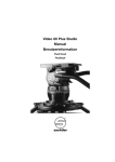
2
3
1
Deutsch
4
FIG. 1 Einstellung
Der Kopf kann in zwei verschiedenen Konfigurationen benutzt werden:
- ohne Schwenkgriff, typisch für Vogelbeobachtung/Foto-Einsatz
- mit Schwenkgriff, typisch für Video-Einsatz
1
A
FIG. 2 – Zusammenbau des Schwenkgriffs
Der Kopf wird mit einem nicht montierten Schwenkgriff geliefert.
Bauen Sie den Schwenkgriff wie folgt zusammen:
1. Entfernen Sie die kleine “Nase” “A”, indem Sie Schraube “B” lösen
ANMERKUNG: bitte bewahren Sie die „Nase“ “A” an einem
sicheren Ort für späteren Einsatz auf.
2. Setzen Sie Schraube “B” in Kopf “C” ein
3. Befestigen Sie den Schwenkgriff, setzen Sie den Einstellkopf “C”
auf den Stativkopf auf und ziehen Sie die Schraube “B” mit einer
Münze fest.
Der Einstellkopf “C” ist so ausgelegt, den Schwenkgriff in
verschiedenen Positionsintervallen zu bewegen und ebenfalls, um für
Links- und Rechtshänder montiert werden zu können.
B
2
90
45
2
0
C
FIG. 4 – Das Equipment auf der Platte befestigen
6
E
FIG. 3 – Die Kameraplatte entfernen
7
FIG. 5 – Das Equipment am Kopf befestigen
Stellen Sie sicher, dass Schraube “E” gelöst ist und setzen Sie die
Platte an, wie in der Figur gezeigt. Sperren Sie die Platte, indem Sie
Schraube “E” in Uhrzeigersinn festziehen.
Anmerkung: die Schnelllöseplatte kann aufgrund des Sicherungsstiftes
nur in einer Richtung eingesetzt werden.
8
ON
5
2
B
OFF
F
F
OF
OFF
3
10
11
12
13
14
F
ON
FIG. 8 – drehen Sie mit einer Hand den Knopf “H” auf die “ON”
Position (dem Pfeil folgend).
FIG. 9 - wenn das Equipment sich nicht bewegen sollte, bedeutet
dies, dass Sie die korrekte Ausgleichseinstellung gefunden haben
OF
16
17
2
ON
OFF
+2
FIG. 10 – wenn das Equipment kippen sollte, suchen Sie den
Balance-Punkt wie folgt:
1
-2
OFF
1. FIG. 11 – ziehen Sie den Knopf “H” heraus und drehen Sie ihn auf
die “OFF” Position
2. FIG. 12 – drehen Sie Ihr Equipment in die Richtung, in die es kippt
3. FIG. 13 – stellen Sie Position „1“ ein, indem Sie „-1“ oder „+1“
wählen, entsprechend der Kipprichtung (immer entgegen der
Kipprichtung), und drehen Sie den Knopf “H” auf die “ON” Position,
bis er in der Position bleibt.
ANMERKUNG: wenn der Knopf auf der “ON” Position ist, befindet
er sich in der Position, die dem Kopf am nächsten ist.
4. FIG. 14 – Prüfen Sie, ob sich das Equipment nicht bewegt: dies
bedeutet, dass Sie den Balance-Punkt gefunden haben.
FIG. 15 - Wenn das Equipment kippen sollte, wiederholen Sie die
obigen Anweisungen und wählen Position “+/- 2“ oder “+/- 3“. Die
Position “+/-3” ist die maximale Einstellposition.
N
ON
ON
F
OF
F
2
G2180
fluid
head
Der Kopf kann mit oder ohne Ausgleichssystem benutzt werden.
FIG. 7
- Lösen Sie die Schraube “F”, während Sie Ihr Equipment halten, um
ein Umkippen zu vermeiden
- bewegen Sie das Equipment, um die “0” Position (durch den Pfeil
angegeben) zu erreichen
OFF
15
ON
Wenn Sie den Kopf mit dem Ausgleichssystem nutzen möchten,
gehen Sie wie folgt vor:
ON
OFF
ON
FIG. 6-7-8-9-10-11-12-13-14-15 – Geweichtsausgleichssystem
Der Kopf ist mit einem Gewichtsausgleichssytem über Federspannung
ausgestattet (ON/OFF, 7 Positionen), um dem dezantralen Gewicht/
den Kippkräften Ihres Equipments entgegenzuwirken. Der Kopf kann
Lasten bis zu 4 kg (8.8 lbs) aufnehmen und das Ausgleichssystem
kann dezentrale/Kipplasten von bis zu 2,5 kg (5.5 lbs) ausgleichen.
FIG. 6 – Ohne Ausgleichssystem verhält sich der Kopf wie ein
Standard-Fluid-Kopf:
1. Vergewissern Sie sich, dass die Kipp-Feststellschraube festgezogen
ist.
2. ziehen Sie mit einer Hand den Knopf “H” heraus und drehen Sie ihn
auf die “OFF” Position (dem Pfeil folgend).
3. mit der anderen Hand halten Sie Ihr Equipment und lösen den
Knopf “F”
ANMERKUNG: wenn der Knopf auf der “OFF” Position ist, befindet
er sich in der Position, die am weitesten vom Kopf entfernt ist (siehe
Detail).
F
F
OFF
ON
9
H
2
OFF
ON
1
H
instructions
mode d’emploi
istruzioni
Gebrauchsanweisung
FIG 16 - Entfernen der Kamera vom Kopf
FIG. 17 – Benutzen Sie die
N Schwenk-Steuerschraube: Reibung und Sperre (360º)
F Kipp-Steuerschraube: Reibung und Sperre (+90º/-90º)
G2,5015 - 06/08
1
1
2
3
1
4
1
A
45
B
2
0
C
2
B
6
E
7
FIG. 5 – How to mount the equipment on the head
Make sure that knob “E” is unscrewed and insert the plate as shown in
figure. Lock the plate in position by screwing knob “E” in a clockwise
direction.
Note: the quick release plate can be inserted in one direction only
due to the safety pin.
8
FF
O
OFF
3
H
10
11
12
13
14
OFF
ON
F
OF
15
16
1
17
ON
FIG. 10 - if the equipment falls, find the balance point as follow
1. FIG. 11 - rotate and pull out the knob “H” to “off” position
2. FIG. 12 - rotate your equipment in the opposite direction of the fall
3. FIG. 13 - reach position “1” selecting “-1” or “+1” accordingly to
the direction of the fall (always opposite direction) and rotate the
knob “H” to “ON” position until it locks into position
NOTE: when set in “on” position, the knob stays in the closest
position to the head
4. FIG. 14 - check if the equipment doesn’t move: it means that you
have reached the balance point
ON
OFF
ON
FIG. 6-7-8-9-10-11-12-13-14-15 – Counter balance system
The head is provided with a spring loaded counter balance system
(ON/OFF, 7 positions) to balance the off centre weight of your
equipment. The head is able to support loads up to 4 kg (8.8 lbs),
and the balance system allows to balance a off centre load up to 2,5
kg (5.5 lbs)
The head can be used with or without counter balance system.
FIG. 6 - Without counter balance system the head behaves like a
standard fluid head:
1. make sure that the tilt control knob “F” is tightened
2. with one hand pull out and fully rotate the knob “H” to “OFF”
position (following the arrow)
3. with the other hand hold your equipment and unscrew the knob “F”
NOTE: when set in “off” position, the knob stays in the furthest
position from the head (see detail)
If you want to use the head with counter balance system, proceed
as follow:
FIG. 7
- unscrew the knob “F” while holding your equipment in order to
prevent it from suddenly flopping
- move the equipment in order to reach the “0” position (indicated by
arrow)
FIG. 8 - with the other hand fully rotate the knob “H” to “ON” position
(following the arrow)
FIG. 9 - if the equipment doesn’t move, it means that you have
reached the balance point
F
F
OFF
ON
9
H
2
OFF
ON
1
FIG. 1 - Preparazione
La testa può essere usata in due diverse configurazioni: senza leva di
comando, tipicamente preferita per birdwatching e fotografia con leva
di comando, tipicamente preferita per impieghi Video
FIG. 4 – How to mount the equipment on the plate
OFF
F
Italiano
FIG. 1 – Installation
La rotule fluide G2180 peut être utilisée dans deux types de
configurations différentes :
- sans levier, pour l’observation animalière ou la photo,
- avec levier, pour la vidéo.
FIG. 3 – How to remove the camera plate
ON
5
Français
FIG. 1 Set up
The head can be used in two different configurations:
- without handle bar, typically for Bird Watching/Photo use
- with handle bar, typically for Video use
FIG. 2 – Assemble Handle Bar
The head is supplied with handle bar not assembled.
Assemble the handle bar as follow:
1. Remove small “nose” “A” by unscrewing the screw “B”
NOTE: please store the “nose” “A” in a safe place for future use
2. Insert the screw “B” into quadrant “C”
3. Attach the handle bar, position the adjustment quadrant “C” on the
head and secure with screw “B” using a coin.
The adjustment quadrant “C” is designed to allow the handle bar to
be positioned at various intervals and also to be rotated at full 360°
for right/left hand users
2
90
English
F
FIG. 15
If the equipment falls down, repeat the instructions above, selecting
position “-/+2” or “-/+3”.
Position “-/+3” is the maximum setting.
FIG. 16 - Remove equipment from the head
FIG. 17 Use
N Pan control knob: friction and lock (360°)
F Tilt control knob: friction and lock (+90/-90°)
2
ON
OFF
+2
-2
OFF
FIG. 3 – Retrait du plateau rapide
FIG. 4 – Fixation de l’appareil sur le plateau rapide
FIG. 5 – Fixation de l’appareil sur la rotule
Assurez-vous que la molette “E” est dévissée, puis insérez le plateau
tel qu’illustré à la figure 5. Bloquez le plateau en position en faisant
tourner la molette “E” dans le sens des aiguilles d’une montre.
Remarque : le plateau rapide ne peut être inséré que dans une seule
direction en raison de la goupille de sécurité.
FIG. 6-7-8-9-10-11-12-13-14-15 – Système de contre-balancement
La rotule fluide G2180 est équipée d’un système de contrebalancement à ressort (ON / OFF - marche / arrêt, 7 positions)
permettant de compenser le déséquilibre du poids de l’appareil.
La rotule peut supporter des charges jusqu’à 4 kg, et le système
de contre-balancement permet de compenser le déséquilibre d’une
charge allant jusqu’à 2,5 kg.
La rotule peut être utilisée avec ou sans système de contrebalancement.
FIG. 6 – Sans système de contre-balancement, la rotule agit comme
une rotule fluide standard :
1. assurez-vous que le bouton de réglage du mouvement de bascule
“F” est bien serré,
2. d’une main, tirez le bouton “H” vers l’extérieur puis faites-le
complètement tourner dans le sens inverse des aiguilles d’une
montre pour atteindre la position “OFF”,
3. de l’autre main, maintenez votre appareil et dévissez le bouton “F”.
Remarque : en position “OFF”, le bouton “H” se trouve dans la
position la plus éloignée de la rotule (voir illustration).
Si vous voulez utiliser la rotule sans système de contre-balancement,
suivez les instructions suivantes :
FIG. 7
- dévissez le bouton “F” tout en maintenant l’appareil afin d’éviter qu’il
ne s’incline,
- déplacez l’appareil de façon à ce que le repère de l’échelle graduée
soit sur la position “0”, tel qu’illustré à la figure 7.
FIG. 8 – Tirez le bouton “H” vers l’extérieur puis faites-le
complètement tourner dans le sens inverse des aiguilles d’une montre
pour atteindre la position “OFF”.
FIG. 9 – Si l’appareil ne bouge pas, cela signifie que vous avez atteint
le point d’équilibre.
FIG. 10 – Si l’appareil s’incline, recherchez le point d’équilibre en
suivant les instructions suivantes :
1. FIG. 11 – Tirez le bouton “H” vers l’extérieur et faites-le tourner
pour atteindre la position “OFF”.
2. FIG. 12 – Placez votre appareil dans la direction opposée à celle
où il s’incline.
3. FIG. 13 – Déplacez l’appareil dans la direction opposée à celle où
il s’incline jusqu’à obtenir la position 1 en utilisant les repères “-1”
ou “+1” selon le sens d’inclinaison de l’appareil, puis faites tourner
le bouton “H” sur la position “ON” jusqu’à ce qu’il se bloque en
position.
Remarque : en position “ON”, le bouton se trouve dans la position la
plus proche de la rotule.
4. FIG. 14 – Vérifiez que l’appareil ne bouge pas : si tel est le cas,
cela signifie que vous avez atteint le point d’équilibre.
FIG. 15 - Si l’appareil penche vers l’avant, répétez la procédure décrite
ci-dessus en sélectionnant la position “-/+2” ou “-/+3”.
La position “-/+3” correspond au réglage maximum.
N
ON
ON
F
OF
FIG. 2 – Montage du levier
La rotule est livrée avec le levier non monté.
Suivez les instructions suivantes pour monter le levier :
1. Faites tourner la vis “B” dans le sens inverse des aiguilles d’une
montre afin de pouvoir retirer la rondelle “A”.
Remarque : conservez la rondelle “A” dans un endroit sûr afin de
pouvoir la réutiliser ultérieurement.
2. Insérez la vis “B” dans l’axe “C”.
3. Fixez le levier en positionnant l’axe de réglage “C” sur la rotule.
Vissez l’ensemble en faisant tourner la vis “B” dans le sens des
aiguilles d’une montre à l’aide d’une pièce de monnaie.
L’axe de réglage “C” permet de positionner le levier à diverses
positions et de pouvoir le tourner complètement à 360° pour qu’il
s’adapte à tous les utilisateurs, gauchers ou droitiers.
2
FIG. 16 – Retrait de l’appareil de la rotule
FIG. 17 – Application
N Bouton de réglage du mouvement panoramique : friction et blocage (360°)
F Bouton de réglage du mouvement de bascule : friction et blocage (+90/-90°)
FIG. 2 - Montaggio della leva di comando
La testa è fornita con leva di comando smontata.
Procedura per montare la leva di comando:
1. Rimuovere il “cono” “A” svitando la vite “B”
NOTA: conservare il “cono” “A” in luogo sicuro per un possibile uso
successivo
2. Inserire la vite “B” nel quadrante dentellato “C”
3. Attaccare la leva, posizionare il quadrante di regolazione “C” sulla
testa e fissarlo saldamente con la vite “B”, serrandola con una
moneta. Il quadrante di regolazione “C” consente di posizionare
la leva a diverse angolazioni su 360° per adattarsi ad utenti destri
e mancini
FIG. 3 - Smontaggio della piastra dalla testa
FIG. 4 - Montaggio dell’apparecchio sulla piastra
FIG. 5 - Montaggio dell’apparecchio sulla testa
Accertarsi che il pomello “E” sia svitato e inserire la piastra come
mostrato in figura. Bloccare la piastra in posizione avvitando il pomello
“E” in senso orario.
Nota: la piastra a sganciamento rapido può essere inserita in una sola
direzione per via del pernino di sicurezza.
FIG. 6-7-8-9-10-11-12-13-14-15 - Sistema di controbilanciamento
La testa è fornita di un sistema per il controbilanciamento a molla
precaricata (ON/OFF, 7 posizioni) per compensare il peso sbilanciato
dell’apparecchio in uso. La testa può portare pesi fino a 4 kg, mentre
il sistema di bilanciamento può compensare uno squilibrio di peso
fino a 2,5 kg
La testa può essere usata con il sistema di controbilanciamento
attivato o disattivato.
FIG. 6 - Con il sistema di controbilanciamento disattivato la testa si
comporta come una normale testa fluida:
1. accertarsi che la ghiera di controllo dell’inclinazione “F” sia stretta
2. con una mano estrarre e ruotare a fondo il pomello “H” portandolo
in posizione “OFF” (come indicato dalla freccia)
3. con l’altra mano reggere l’apparecchio e svitare la ghiera “F”
NOTA: in posizione “OFF” il pomello rimane scostato dalla testa
(vedere dettaglio)
Per usare la testa col sistema di controbilanciamento, procedere come
indicato di seguito:
FIG. 7
- svitare la ghiera “F” mentre si regge l’apparecchio per evitarne la
caduta
- portare l’apparecchio sulla posizione “0” (indicata dalla freccia)
FIG. 8 - con l’altra mano ruotare il pomello “H” portandolo in posizione
“ON” (come indicato dalla freccia)
FIG. 9 - se l’apparecchio non si muove è stato raggiunto il punto di
bilanciamento
FIG. 10 - se l’apparecchio tende ad inclinarsi, trovare il punto di
bilanciamento come indicato di seguito
1. FIG. 11 - ruotare ed estrarre il pomello “H” sulla posizione “OFF”
2. FIG. 12 - inclinare l’apparecchio in direzione opposta a quella di
caduta
3. FIG. 13 - inserire un valore di compensazione “1” selezionando “-1”
o “+1” in base alla direzione di caduta e ruotare il pomello “H” sulla
posizione “ON” fino a farlo bloccare in posizione
NOTA: in posizione “OFF” il pomello rimane accostato alla testa
4. FIG. 14 - verificare che l’apparecchio non tenda ad inclinarsi.
Se l’apparecchio non si muove è stato raggiunto il punto di
bilanciamento
FIG. 15 - Se l’apparecchio tende ad inclinarsi, ripetere la procedura
riportata più sopra, selezionando una posizione “-/+2” o “-/+3”. La
posizione “-/+3” indica il massimo controbilanciamento possibile.
FIG. 16 - Smontaggio dell’apparecchio dalla testa
FIG. 17 Uso
N Pomello di controllo della panoramica: frizione e blocco (360°)
F Ghiera di controllo dell’inclinazione: frizione e blocco (+90/-90°)