1
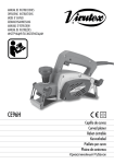
Modelo · Model · Modèle · Modell · Modello · Modelo
AP98
5396049
MANUAL DE INSTRUCCIONES Español (p. 3)
OPERATING INSTRUCTIONS English (p. 6)
MODE D' EMPLOI Français (p. 8)
GEBRAUCHSANWEISUNG Deutsch (s. 10)
MANUALE D'ISTRUZIONI Italiano (p. 13)
MANUAL DE INSTRUÇÕES Portugués (p. 15)
Cepillo enrasador
Edge lipping planer
Rabot à araser
Umleimerhobel
Pialletto per bordi
Plaina de cantos
MANUAL DE INSTRUCCIONES
OPERATING INSTRUCTIONS
MODE D'EMPLOI
GEBRAUCHSANWEISUNG
MANUALE D'ISTRUZIONI
MANUAL DE INSTRUÇÕES
página/page
seite/pagina
страница
ESPAÑOL
Cepillo enrasador AP98
3
ENGLISH
AP98 Edge lipping planer
6
FRANÇAIS
Rabot à araser AP98
8
DEUTSCH
Umleimerhobel AP98
10
ITALIANO
Pialletto per bordi AP98
13
PORTUGUÉS
Plaina de cantos AP98
15
Fig. 1
Fig. 2
2
Fig. 4
Fig. 3
Fig. 6
Fig. 5
Detalle W
Ver detalle W
Fig. 8
Fig. 7
3
5399059 SET OF 2 REV. BLADE BEARINGS
6446073 3.5 m EXTERNAL DUST COLLECTION
HOSE
5. GENERAL DESCRIPTION
AND APPLICATIONS
The AP98 edge lipping planer comes equipped
with:
• Hard-metal reversible blades.
• Knob for adjusting cutting depth, enabling a
flushing height from 11 mm to 0.
• Side guides, for flushing work that takes the edge
of the piece as a reference.
• Dust collector connection.
• Upwardly-engaging safety button, which prevents
the machine from being started up accidentally.
The AP98 edge lipping planer is a tool that will
prove useful to carpenters, fitters and restorers.
It has been especially designed for the recessing
and flushing of: woods, varnished woods, stratified
woods, softwoods and synthetic materials.
For maximum performance, the selfsame weight
of the machine is the only pressure that should
be applied; do not force it, which will reduce its
speed and output.
6. STARTING AND STOPPING THE MACHINE
This edge lipping planer is equipped with an
upwardly-engaging safety button that prevents the
machine from being started up accidentally.
To start up the machine, press down on the safety
button Z while simultaneously depressing the power
button A1 (Fig. 1).
Before plugging in the machine, ensure that the
power supply voltage is compatible with that stated
on its specifications plate, and that the blade-holder
guard is properly attached.
7. CUTTING ADJUSTMENTS
FLUSHING HEIGHT
Unscrew knob A (Fig. 1) in the counter-clockwise
direction until reaching the end of the thread. Spin
the wheel B to raise or lower the cutter-block, adjusting it to the necessary flushing height.
After setting the flushing height, screw on the knob
A in the clockwise direction until it becomes firmly
tightened in place.
8. SIDE GUIDE
The side guide C (Fig. 1) enables flushing by following the edge of the board. It can be set using
knob D and then tightened using the 6-mm Allen
wrench E.
9. DUST COLLECTOR CONNECTION
The machine is equipped with a dust collector
connection F (Fig. 1) which can be used for
connection to our AS182K, AS282K and AS382L
dust collector or any industrial equivalent via the
STANDARD DUST COLLECTOR ATTACHMENT
(ref. 6446073).
WARNING! The dust collector connection F (Fig.
1) must never be set up on the machine if no
collector is used. This would prevent the free
ejection of chips.
10. REPLACING AND
CONTROLLING THE BLADES
ATTENTION: Disconnect the equipment from the
mains before carrying out this operation.
1. REPLACING BLADES AND
BLADE HOLDERS
To replace blades or reverse them in order to use
the second cutting edge, follow the steps below:
Loosen the two fastening screws G (Fig. 2) in the
clockwise direction using the service key.
Turn the cutter-block casing to a suitable position
so that the blade H can be lined up with the groove I of the guard, so as to have enough space
to move and laterally remove the blade from its
housing in holder J.
Remove any dust and resin from the seats of the
cutter-block and supports before inserting new
blades.
Replace the old blade with a new one, or with the
same blade reversed, using its second cutting
edge.
Reinsert the blade in the recess of the blade
holder J (Fig. 3), ensuring that the blade H and its
holder J do not protrude out from the side of the
cutter-block P.
Securely tighten the two screws G (Fig. 2) in the
counter-clockwise direction using the service
key.
If it is necessary to replace the blade holders J of
the cutter-block, loosen the 2 screws K (Fig. 4),
unscrew the screw L and remove the cutter-block
guard M, which will leave the blade bearings J
in view.
2. ADJUSTING BLADES AND
BLADE HOLDERS
Blade holders are regulated before leaving the
factory and do not require readjustment when
changing the blade. Nonetheless, if for any reason
they have to be adjusted, do so as follows:
Using the knob A and the wheel B (Fig. 1 and 6),
align and block the surface of the base N (Fig.
5) with the cutting edge of the blade in the best
condition, which will used as a reference.
In the event that blade holders or blades become
7
lost or worn out, leave a distance of 1 mm between the surface of base N and the diameter of
the cutter-block P (Fig. 6). Loosen slightly in the
clockwise direction the two screws G (Fig. 2) of
the blade blade holder J, which should be adjusted
using the service key.
Place a rule over the base and adjust the screws R
(Fig. 5) in order to withdraw or retract the blade holder
with the fitted blade until the entire length of its cutting
edge is flush and parallel with the base N.
Check that the side of the blade H does not protrude
out from its holder J, and that the blade holder is
lined up with the side of the cutter-block P (Fig. 3),
and tighten the two screws G (Fig. 2) in the counterclockwise direction with the service key.
WARNING! Ensure that the 4 screws G (Fig. 2) are
well-tightened before resuming work with the edge
lipping planer after making any blade changes or
blade holder adjustments.
When replacing the cutter-block, use only original
VIRUTEX components.
11. CHANGE OF THE DRIVING BELT
ATTENTION: Disconnect the equipment from the
mains before carrying out this operation.
Remove the protective cover S (Fig. 7), unscrewing
the screw T that fastens it.
Unscrew and remove knob D (Fig. 1). Loosen the
two screws U (Fig. 7), dislodge the motor unit X
from its interior housing and remove the worn-out
belt V from the driving pulley.
Carefully clean the pulley and driving wheel before
replacing the belt with a new genuine VIRUTEX
belt.
Mount the new toothed belt X, making sure that
its teeth are properly intermeshed with those of
the blade-holder pulley and those of the driving
wheel.
Once the belt has been fitted onto the pulleys, refit
the motor unit V in its housing, carefully screwing
down the two screws U (without forcing them),
until it is properly seated, and put knob D back in
place (Fig. 1).
12. MAINTENANCE OF
BRUSHES AND COLLECTOR
WARNING! Always remove the plug from the
mains socket before carrying out any work on the
machine.
It is important that brushes be changed when they
have a minimum length of 5 mm.
Unscrew the lid Y (Fig. 8) and remove the brushes
from the guides.
Replace brushes with genuine VIRUTEX brushes
and check to ensure that they slide smoothly in
their guides.
8
After screwing the lid back on, it is recommended to
leave the machine running for 15 minutes in order
to ensure that brushes adapt properly.
WARNING! Should you detect burns or ribbing
on the collector, have it repaired at a VIRUTEX
technical service outlet.
13. NOISE AND VIBRATION LEVEL
The noise and vibration levels of this electrical
device have been measured according to the
European standard EN50144.
The noise level in the workplace can exceed 85
dB(A), in which case it is necessary for the user
to take noise protection measures.
14. WARRANTY
All VIRUTEX power tools are guaranteed for 12
months from the date of purchase, excluding any
damage which is a result of incorrect use or of
natural wear and tear on the machine. All repairs
should be carried out by the official VIRUTEX
technical assistance service.
VIRUTEX reserves the right to modify its products
without prior notice.
Français
RABOT À ARASER AP98
1. INSTRUCTIONS DE SECURITE
POUR L'UTILISATION DU RABOT
ATTENTION! Lire attentivement la BROCHURE
D'INSTRUCTIONS GÉNÉRALES DE SÉCURITÉ
jointe à la documentation de la machine.
1. Avant de brancher la machine, vérifier si la tension
d'alimentation correspond à celle indiquée sur la
plaque des caractéristiques.
2. Porter des lunettes de sécurité pour travailler
avec cette machine.
3. Prendre soin de ne pas mettre les mains sur la
zone de coupe, et de toujours prendre la machine
par la poignée.
4. Éviter de couper des clous. Vérifier la surface
à travailler avant de rabotter.
5. Débrancher la machine du secteur avant de
faire toute opération d'entretien.
6. Utiliser uniquement des couteaux d'origine
VIRUTEX. Ne jamais utiliser de couteaux qui ne
seraient pas aiguisés, ayant des mesures incorrectes, défectueux ou en mauvais état.
7. Toujours utiliser le porte-lames et les supports de
lames d'origine VIRUTEX montés sur la machine.
En cas de besoin, les remplacer par des pièces
de rechange d'origine VIRUTEX.
utiliser le tranchant disponible sur la seconde face
de coupe, effectuer les opérations suivantes:
Dévisser les deux vis de fixation G, (Fig. 2), en
utilisant la clé de service, dans le sens des aiguilles
d'une montre.
Faire tourner le corps du porte-couteaux pour obtenir une position correcte permettant de mettre face
à face le couteau H avec la rainure I du protecteur,
afin d'avoir l'espace suffisant pour déplacer et
extraire latéralement le couteau de son logement
dans le support J.
Il convient de nettoyer la poussière et la résine se
trouvant dans les logements du porte-couteaux
et les éléments de serrage avant de monter des
couteaux neufs.
Remplacer le couteau par un neuf ou inverser celui
que l'on avait retiré pour utiliser le tranchant de sa
seconde face de coupe.
Introduire de nouveau le couteau dans la rainure du
profil du support couteau J, (Fig. 3), en prenant soin
d'éviter que le couteau H et son support J dépassent
sur le côté du corps du porte-couteaux P.
Serrer fermement les deux vis G, (Fig. 2), dans le
sens contraire des aiguilles d'une montre avec la
clé de service.
Pour remplacer, en cas de besoin, les supports
couteaux J, du corps porte-couteaux, il faut dévisser les 2 vis K, (Fig. 4), dévisser la vis L, retirer
le protecteur porte-couteaux M pour dégager les
supports couteaux J.
2. RÉGLAGE DES COUTEAUX
ET DES SUPPORTS COUTEAUX
Les éléments de serrage des couteaux sont réglés d'origine et n'ont pas à être réajustés quant
on change les couteaux. Cependant si pour une
raison quelconque il fallait les réajuster, faire
comme suit:
À l'aide du bouton A et du galet B, (Fig. 1 et 6),
aligner et bloquer la surface du socle N, (Fig. 5),
avec le tranchant du couteau, en meilleur état,
que l'on prendra comme référence.
En cas de perte ou de détérioration totale des
supports couteaux ou des couteaux, laisser une
distance de 1 mm entre la surface du socle N et
le diamètre du corps du porte-couteaux P, (Fig. 6).
Dévisser légèrement, dans le sens des aiguilles
d'une montre, les deux vis G, (Fig. 2), du support
couteau J, qu'il faut régler avec la clé de service.
Mettre une règle sur le socle et régler les vis R,
(Fig. 5), pour dégager ou cacher le support, avec le
couteau monté, pour que toute la longueur du tranchant soit bien arasée et parallèle au socle N.
Vérifier que le côté du couteau H ne dépasse
pas de son support J et que le support couteau
est bien aligné avec le côté du porte-couteaux P,
10
(Fig. 3), serrer les deux vis G, (Fig. 2), dans le
sens contraire des aiguilles d'une montre avec la
clé de service.
ATTENTION! S'assurer que les 4 vis G, (Fig. 2)
sont bien serrées avant de reprendre le travail
avec le rabot à araser, après tout changement de
couteaux ou réglage de leurs supports.
Pour les pièces de rechange de la tête à couteau,
utiliser exclusivement des composants d'origine
VIRUTEX.
11. SUBSTITUTION DE LA
COURROIE DE TRANSMISSION
ATTENTION! Débrancher la machine du secteur
avant de réaliser cette opération.
Retirer le couvercle de protection S (Fig. 7), en
dévissant la vis T qui le fixe.
Dévisser et retirer le bouton D, (Fig. 1). Dévisser
les deux vis U, (Fig. 7), déplacer le bloc moteur
X dans son emboîtement intérieur et retirer de la
poulie motrice, la courroie V détériorée.
Nettoyer soigneusement la poulie et la roue motrice avant de remplacer la courroie par une autre,
d'origine VIRUTEX.
Monter la nouvelle courroie crantée V, en prenant soin
de bien engrener ses dents avec celles de la poulie
du porte-couteaux et celles de la poulie motrice.
Quand la courroie est bien située sur les poulies,
emboîter de nouveau le bloc moteur X, dans son
logement, en vissant peu à peu et sans forcer les
deux vis U, jusqu'à ce qu'il soit bien fixé, et installer
de nouveau le bouton D, (Fig. 1).
12. ENTRETIEN DES BALAIS
ET DU COLLECTEUR
ATTENTION! Débrancher la machine du secteur
avant de faire toute opération d'entretien.
Il est recommandé de remplacer les balais quand
ils atteignent 5 mm de longueur minimum .
Dévisser le bouchon Y, (Fig. 8), et retirer le charbon
du guidage.
Remplacer les balais par d'autres, d'origine VIRUTEX et vérifier qu'ils glissent aisément dans
leurs guidages.
Visser de nouveau le bouchon de leur logement. Il
est recommandé de laisser la machine en marche
durant 15 minutes pour que les balais s'adaptent
correctement.
ATTENTION! Si on constate que le collecteur présente des brûlures ou des ressauts, il faut le faire
réparer par un Service Technique VIRUTEX.
13. NIVEAU DE BRUIT ET DE VIBRATIONS
Le niveau de bruit et de vibrations de cet outil
électrique a été mesuré conformément à la Norme
Européenne EN50144.