1
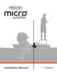
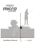
FCC Part 15.19 Warning Statement (Required for all Part 15 devices)
THIS DEVICE COMPLIES WITH PART 15 OF THE FCC RULES. OPERATION IS SUBJECT TO THE
FOLLOWING TWO CONDITIONS: (1) THIS DEVICE MAY NOT CAUSE HARMFUL INTERFERENCE, AND
(2) THIS DEVICE MUST ACCEPT ANY INTERFERENCE RECEIVED, INCLUDING INTERFERENCE THAT MAY
CAUSE UNDESIRED OPERATION.
FCC Part 15.21 Warning Statement
NOTE: THE GRANTEE IS NOT RESPONSIBLE FOR ANY CHANGES OR MODIFICATIONS NOT
EXPRESSLY APPROVED BY THE PARTY RESPONSIBLE FOR COMPLIANCE. SUCH MODIFICATIONS
COULD VOID THE USER’S AUTHORITY TO OPERATE THE EQUIPMENT.
IC RSS-GEN, Sec 7.1.3 Warning Statement (Required for license-exempt devices)
ENGLISH: This device complies with Industry Canada license-exempt RSS standard(s). Operation is subject
to the following two conditions: (1) this device may not cause interference, and (2) this device must accept
any interference, including interference that may cause undesired operation of the device.
FRENCH: Le présent appareil est conforme aux CNR d’Industrie Canada applicables aux appareils radio
exempts de licence. L’exploitation est autorisée aux deux conditions suivantes : (1) l’appareil ne doit pas
produire de brouillage, et (2) l’utilisateur de l’appareil doit accepter tout brouillage radioélectrique subi,
même si le brouillage est susceptible d’en compromettre le fonctionnement.
IC RSS-GEN, Sec 7.1.2 Warning Statement (Required for Transmitters)
ENGLISH: Under Industry Canada regulations, this radio transmitter may only operate using an
antenna of a type and maximum (or lesser) gain approved for the transmitter by Industry Canada. To
reduce potential radio interference to other users, the antenna type and its gain should be so chosen
that the equivalent isotropically radiated power (e.i.r.p.) is not more than that necessary for successful
communication.
FRENCH: Conformément à la réglementation d’Industrie Canada, le présent émetteur radio peut
fonctionner avec une antenne d’un type et d’un gain maximal (ou inférieur) approuvé pour l’émetteur
par Industrie Canada. Dans le but de réduire les risques de brouillage radioélectrique à l’intention
des autres utilisateurs, il faut choisir le type d’antenne et son gain de sorte que la puissance isotrope
rayonnée quivalente (p.i.r.e.) ne dépassepas l’intensité nécessaire à l’établissement d’une communication
satisfaisante.
Wireless Standard Foot Switch
Congratulations on your purchase of the Power-Pole® Foot Switch
featuring C-Monster Control System.
To add the Power-Pole Foot Switch follow these simple step by step instructions.
Compatible with all C-Monster Control Systems
Hardware:
Installation Tools:
A Qty. (1) Up button
B Qty. (1) Down button
C Qty. (6) #8 x 1.5” Pan head screws
• #2 Phillips-head screwdriver
• 1/8” drill bit
• Electric or battery operated drill
A
B
IC RSS-102, Sec 2.6 Warning Statements
ENGLISH: The applicant is responsible for providing proper instructions to the user of the radio device, and
any usage restrictions, including limits of exposure durations. The user manual shall provide installation
and operation instructions, as well as any special usage conditions, to ensure compliance with SAR and/or
RF field strength limits. For instance, compliance distance shall be clearly stated in the user manual.
FRENCH: Le mode d’emploi des appareils destinés à l’utilisation contrôlée doit aussi inclure des
informations sur les caractéristiques de fonctionnement de l’appareil; les instructions de fonctionnement
pour assurer la conformité avec SAR et / ou les limites d’intensité de champ RF; informations sur
l’installation et l’exploitation d’accessoires pour assurer le respect des SAR et / ou les limites d’intensité de
champ RF; et les coordonnées où l’utilisateur peut obtenir des informations sur l’exposition canadienne de
radiofréquences et la conformité. Autres renseignements connexes peuvent également être inclus.
C
2
To activate your warranty or find a Power-Pole
Certified Warranty Center, go to www.power-pole.com
9010 Palm River Road, Tampa, Florida 33619
phone 813.689.9932 • fax 813.689.8883 • power-pole.com
If any hardware is missing from this package please contact Tech Support immediately at 813-689-9932 opt 2
Pairing and Operation
Pairing Foot Switches:
Changing the Battery and Installation
Hydraulic Pump Unit (HPU)
1. Press and hold the PROGRAM button on the top of the
unit for 3 seconds until the LED turns green in color
(HPU will also beep).The unit is now ready to be paired
with the foot switches.
PROGRAM
2. Take the foot switch to a dry location and separate the
foot switch cover from its base using a small flat head
screwdriver (See Figure 1)
3. Remove the rubber switch membrane and the circuit
board from the foot switch base (See Figure 2)
NOTE: If dual units are installed, repeat Steps 1-3 to pair
multiple units to a single foot switch. Up to ten (10)
wireless controllers can be programmed to each unit.
Figure 2
4. Remove the battery from the holder on the back of the
circuit board and replace with any CR2032 3V Lithium
Coin Battery.
MICRO Driver Unit
PROGRAM
LED
4. The foot switches are now paired to the unit. Test their
functionality by following the operating instructions
to ensure that the pairing procedure was completed
successfully.
Figure 1
Figure 1
1. Remove the (3) screws with a #2 Phillips-head
screwdriver.
LED
2. Press the UP foot switch button for 1 second and release
(See Figure 1) The green LED on the unit(s) will initially
turn off, then flash green steadily (HPU will also beep)
indicating that the pairing is complete.
3. For the DOWN foot switch button, repeat Step 1 to
enter programming mode. Next, press the DOWN foot
switch button for 1 second and release. (See Figure 2)
The green LED on the unit(s) will initially turn off, then
flash green steadily (HPU will also beep) indicating that
the pairing is complete.
Changing the Battery:
Figure 2
SWITCH COVER
CIRCUIT BOARD
5. Inspect the inside of the foot switch case for signs of
moisture or damage to the rubber seal. If the rubber
seal appears damaged, or if moisture is found, please
contact our technical support staff at
813-689-9932 option 2.
Figure 3
CIRCUIT BOARD
6. Place the circuit board back into its base with circuit
board level and small black caps placed over each
circuit board button (See Figure 3)
BLACK CAPS
NOTE: Each small black cap when pressed should push
down and come up when released. If the black cap
does not push down, remove black cap, rotate 1
quarter turn and re-install.
Figure 4
SWITCH COVER
7. Install rubber switch membrane back into the foot
switch base and ensure that the rubber switch
membrane is seated properly prior to installing the
cover (See Figure 4)
Operating Instructions:
Installation Instructions:
1. To raise or lower the Power-Pole anchor, press and hold either the UP or the DOWN foot switch
button. The anchor will only continue to move so long as you keep the button depressed.
1. Locate a suitable area with a flat surface to mount
the UP and DOWN foot switches.
Auto Mode: Double tapping (depressing and releasing 2 times within 1 second) either the UP
or the DOWN foot switch button will cause the anchor to retract or deploy automatically. The
anchor will continue to move in said direction until it either retracts completely (up) or senses a
solid bottom surface (down).
2. Mark and drill a hole with 1/8” drill bit to fasten
foot switches using the (6) screws C supplied
(do not over tighten).
C
C
NOTE: The wireless foot switch comes set to 100% speed setting. This can be adjusted by
downloading the C-Monster App and connecting to the system via Bluetooth with your Android
powered smart phone. For more information refer to your Owner’s Guide.
For Technical Support Call 813.689.9932 option 2
For Technical Support Call 813.689.9932 option 2
C