1
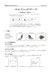
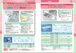
12年06月M16Y0212
INSTALLATION MANUAL
バルブスプリング
VALVE SPRING
日本語・・・・・・・・・・・・・・2p
English・・・・・・・・・・・・・・7p
●この取扱説明書を良く読んでからお使いください。
●自動車メーカーの発行する整備要領書と併せてお使いください。
●取り付け後も大切に保管してください。
●販売店様で取り付けをされる場合は本書を必ずお客様へお渡しください。
TOMEI 製品のお買い上げありがとうございます。
高度なチューニングに用いられるバルブスプリングは、大きなバルブリフト量と高回転に対応し、
バルブをカムプロフィール通りに正確に運動させなければならないため、その生産には高度な
設計技術と生産技術が必要です。TOMEIは、材質や表面処理を含む新たな設計思想を提案、
許容回転数を上昇させると共に、あらゆる角度からの信頼性を確保しました。
●
●
●
●
Please carefully read this manual prior to installation.
Please also refer to the Vehicles Official Service Manual with this Manual.
After the installation has been completed please keep this manual for future reference.
If the install was done in a shop please make sure to give this manual to the owner.
Thank you for purchasing a TOMEI product.
These Valve Springs are designed for high level tuning to suit high cam lift profile camshafts and for
use at high engine speeds. Since these are application specific you will need to follow the application
guidelines for each valve springs package. TOMEI has designed these for maximum life to cope with
the harsh conditions of high end performance.
1
品番・適合
エンジン型式
タイプ
リフト(mm)
品番
∼11.50
163052
A
∼10.85
173001
B
∼11.50
173002
C
∼11.50
163016
A
∼8.80
13203R855
B
∼10.25
163022
∼10.35
13203R800
A
∼12.50
173004
B
∼12.50
163055
RNN14
∼12.50
13203R301 ダブルスプリング
∼10.35
13203R410
A
∼7.75
163038
ダブルスプリング
B
∼7.90
163050
ダブルスプリング
VR38DETT
備考
楕円線材
専用リテーナー付 ※ベース円Φ30カムシャフト用
TOMEIバルブリフター要併用
ダブルスプリング 専用リテーナー付 ベース円Φ30カムシャフト用
TOMEIバルブリフター要併用 RB26DETT
R33 RB25DE(T)
RB20DE(T)
VG30DE(TT)
SR20DE(T)
CA18DE(T)
IN リテーナー付 ソリッド専用 ダブルスプリング 専用チタンリテーナー付 スプリングシート付
A12/14/15
A
7.80∼9.00 13203R200
C
9.00∼10.00 13203R202
A
7.80∼9.00 13203R500
C
9.00∼10.00 13203R502
L4
L6
VQ35DE/HR
∼11.0
163037
楕円線材 ハイリフト対応タイプ
4B11/G4KF
∼11.5
163051
楕円線材 ハイリフト対応タイプ
4G63 ※1
∼11.5
163034
楕円線材 ハイリフト対応タイプ
4G93 ※2
∼12.0
163050
EJ20/25
∼11.0
163057
ハイリフト対応タイプ
3S-GE ※3
∼10.0
163026
スプリングシート付
K20A
∼13.4
163053
ハイリフト対応タイプ
※1 EVO8/9に使用する場合はTOMEI チタニウムリテーナー、もしくはEVO7用純正リテーナーが必要です。
※2 地域限定専売製品となります。
※3 適合/TOYOTA MR2(SW20) 3S-GE 93.11~97.4(インナーシム)/
TOYOTA セリカ(ST 202) 3S-GE 93.9~97.4(インナーシム)
2
■TOMEI NEW−CONCEPT バルブスプリング特徴
(L4/6を除く)
●改良型シリコンクロムオイルテンパー線
シリコンクロムオイルテンパー線材をさらに進化させた改良型を採用し、最適な設計と合わせることで、
“①ジャンプ”や“②バウンス”の発生を抑え最高回転数を上昇させました。また、“③疲労限度”を上昇させました。
●多段不等ピッチスプリング
1本のスプリングの中で、バネレートを数段組み合わせることで、固有振動数を飛躍的に高くする設計思想。
共振を起こりにくくし、“④サージング”の抑制効果を向上しました。
●窒 化
スプリングに窒素を浸透させ、表面に大きな圧縮応力を残留する表面処理法です。
ハイリフトカムシャフトに対応した“疲労限度”を確保するために採用しました。
●ショットピーニング
スプリングの表面に小さな鋼球を高速で無数に打ち付ける作業で、ばねの表面に圧縮の残留応力を形成させ、
“疲労限度”を増す工程です。従来から実施されているものを、設計変更に併せて最適値に変更しました。
●ホットセッチング
高温状態のスプリングに実際に使用する荷重以上の大きな荷重を加え、永久変形を生じさせる工程です。
長期に渡り最高の性能を確保するため“⑤へたり”を防止しました。
①ジャンプ
高回転時、バルブがカムの回転に追従できずに勝手にリフトし、その後戻るときに
カム面に激突しそのまま収まらずに跳ねる現象
②バウンス
バルブが戻ったときにバルブがバルブシートに密着せずにショックで跳ね返り、何回か
繰り返す現象
③疲 労
(つかれ)
スプリングの繰り返し作動中に折損が発生すること。振幅の大小に関係する(リフトが
大きいと疲労しやすい)。
④サージング
(サージ)
バルブスプリングの素線が振動を起こし(共振)、ばね全体が激しく振動したり、
バネの中で波が往復するような振動となる現象
⑤へたり
使用中にスプリングの荷重(自由高さ)が減少してしまう現象。作動中の最大応力、
使用時間に関係する。
●楕円線材の採用 ※4G63、VQ35、VR38DETTのみ 線材を楕円形状とすることで線間の密着長を短縮し高リフトのカムに対応を可能にしました。
一般的な線材の断面
伸長時
収縮時
楕円線材の断面
伸長時
収縮時
3
使用上の注意
■ 本品は自動車競技という特殊用途に用いるため、取付は特別の訓練を受けた整備士が、設備の整った作業場で
実施してください。
■ 取り付けの際は、適切な工具と保護具を使用しないとけがにつながり危険です。
■ バルブスプリングの取り付けに伴う、エンジンの分解組立、および点検方法は各自動車メーカーの発行する
整備要領書を参照してください。
■ カムシャフトのリフトに応じた、適切なスプリングを使用してください。
■ 組付前に必ず洗浄し、ゴミや、識別ペイントが洗い落とせるものは落としてください。
■ 定められたバルブリフト量(リフト長)よりも大きい入力を与えないでください。過度な入力がかかるとスプリング
全長が変化します。
■ バルブスプリングの負担を低減し、耐久性と回転余裕を確保するため、TOMEIカムシャフトの使用を推奨します。
Gコントロール機能が無いカムは、カム開度とリフト量の組み合わせによって、バルブスプリングに著しい負担を
かけるので注意が必要です。
■ 使用するバルブスプリングの種類より、取り付け時に注意が必要なものがあります。
【不等ピッチスプリングの場合】
ピッチが密の方を下にして取り付けてください。
※4G63用には識別色がついていません。ピッチが密の方を下にして取り付けてください。
等ピッチ (P1=P2)
P1
P2
不等ピッチ (P1>P2)
上
P大
P1
P小
P2
下
【ダブルスプリングの場合】
インナースプリングシートを先に入れてからステムシールを取り付けてください。
【RB26DETT用 Bタイプ/Cタイプの場合】
RB26DETT用BタイプおよびCタイプは、同梱の専用リテーナーを使用する事を前提として設計されています。
また装着には、ベース円φ30のカムシャフトおよびTOMEI バルブリフターを併用してください。 【SR20用 Bタイプ(ダブルスプリング)の場合】
インナースプリングシートを先に入れてからステムシールを取り付けてください。
約0.5mm
SR20用 Bタイプに使用するリテーナーは
STD品と形状が異なる為、チューニングの
仕様によってはロッカーアームとリテーナー
が干渉する場合 があります。
ロッカーアーム先端とリテーナーのクリア
ランス(1mm程度)が確保できない場合は、
左図のようにロッカーアームを切削してくだ
さい。
2∼3mm
※切削は使用するロッカーアーム全てに行ってください。
※切削箇所はシム側、ガイド側ともに行ってください。
4
仕様
※仕様は設計値です。
線形
VR38DETT
IN
EX
RB26DETT
Aタイプ
Bタイプ
Cタイプ
自由長
(mm)
3.15×3.95
45.1
3.05×3.80
46.2
Φ3.90
44.0
Φ4.20
45.0
インナー
Φ2.00
43.1
アウター
Φ4.20
45.0
セット長
(mm)
36.6
33.7
37.7
40.2
IN 30.2
EX 35.2
40.2
Φ3.80
Φ3.80
Φ3.90
Φ3.90
Φ4.00
Φ2.50
Φ4.00
36.2
44.5
41.0
41.0
48.0
35.2
48.0
30.6
34.4
35.0
35.0
40.0
32.2
40.0
Φ2.30
Φ3.80
43.3
46.4
31.0
38.0
Φ2.70
Φ3.80
45.9
48.1
34.7
38.0
Φ2.70
Φ4.00
40.0
48.0
35.5
40.0
3.00×3.75
3.40×4.25
3.60×4.50
49.1
41.6
50.8
43.1
45.1
41.0
48.6
37.0
35.0
39.6
37.0
36.2
35.0
40.0
組合時
R33
RB25DET
IN
EX
INリテーナー付
RB20/VG/CA(DE/DET)
SR20DE(T) Aタイプ
Bタイプ
RNN14
(SR20DET)
インナー
アウター
組合せ時
A12/14/15
Aタイプ
Bタイプ
VQ35DE/HR
4B11/G4KF
4G63
4G93 ※
EJ20/25
3S-G
K20A
インナー
アウター
組合時
インナー
アウター
組合せ時
インナー
アウター
組合時
Φ3.90
Φ3.80
Φ3.90
Φ4.20
リフト長 密着長 セット荷重
リフト荷重
(mm)
(mm)
(kgf)
(kgf)
25.4
24.3
23.5±7%
76.5±7%
22.5
21.5
34.0±7%
77.0±7%
26.1
27.2
24.0±7%
77.2±7%
28.0
29.0
24.0±7%
97.8±7%
IN 19.0
IN6.3±8% IN14.0±8%
17.9
EX 24.0
EX3.6±8% EX10.3±8%
28.0
24.0±7%
97.8±7%
29.0
IN30.3±8% IN111.8±8%
EX27.6±8% EX108.1±8%
19.0
23.9
62.4±5%
21.6
22.8
38.5
72.0±5%
25.6
24.0
24.2±7%
80.6±7%
25.0
24.0
24.2±7%
80.6±7%
25.0
26.5
25.6±7%
81.6±7%
27.5
18.7
3.4±8%
23.4±8%
19.7
26.5
25.6±7%
81.6±7%
27.5
29.0±8%
105.0±8%
17.5
9.0
24.0
19.0
24.4
20.0
60.0
26.0
29.0
84.0
21.2
12.5
34.0
23.7
25.2
58.9
23.0
27.0
92.9
35.5
22.5
28.0±7%
24.0
7.1±7%
27.5
26.5
25.6±7%
81.6±7%
32.7±7%
109.6±7%
25.0
24.0±6%
56.8±6%
26.0
21.5
85.0±7%
27.0±7%
23.0
27.1
33.6±5%
28.1
81.7±6%
29.7±7%
24.0
25.0
82.6±7%
23.9
85.0±6%
32.0±6%
25.5
25.0
24.0
24.2±7%
80.6±7%
26.6
25.0
35.0±7%
106.0±7%
※地域限定専売製品となります。
5
材質
処理
色
NHK620
NHK620
SWOSC-VX
SWOSC-VX
窒化
窒化
窒化
窒化
青
白
白
黄
SWOSC-VX
窒化
緑
SWOSC-VX
窒化
黄
SWOSC-V
SWOSC-V
SWOSC-VX
SWOSC-VX
SWOSC-VX
SWOSC-VX
SWOSC-VX
窒化 緑
窒化 ピンク
窒化 青
窒化 青
窒化 赤
窒化 赤
窒化 赤
SWOSC-V
SWOSC-V
窒化
窒化
無
無
SWOSC-VX
SWOSC-VX
窒化
窒化
青
青
NHK507
SWOSC-VX
窒化
白
赤
SWOSC-VX
NHK507
SWOSC-VT
NHK507
NHK-620
SWOSC-VX
NHK-620
窒化 青
窒化 水色
窒化 無
窒化 橙
窒化 青
窒化 青
窒化 緑
PART NUMBER / APPLICATION
ENGINE TYPE
TYPE
VR38DETT
RB26DETT
LIFT (mm) PART NO.
NOTES
∼11.50
163052
Oval wire core
A
∼10.85
173001
B
∼11.50
173002
C
∼11.50
163016
A
∼8.80
13203R855
B
∼10.25
163022
∼10.35
13203R800
A
∼12.50
173004
B
∼12.50
163055
RNN14
∼12.50
13203R301 Double Spring
∼10.35
13203R410
A
∼7.75
163038
B
∼7.90
163050
With special retainers
For Φ30mm base Circle Camshafts
TOMEI Valve Lifters Required
Double Springs and special retainers
For Φ30mm base circle camshafts
TOMEI Valve Lifters Required
R33 RB25DE(T)
RB20DE(T)
VG30DE(TT)
SR20DE(T)
CA18DE(T)
With Intake side retainers for solid conversions
Double springs and special titanium retainers With spring seats
Double Spring
A12/14/15
A
7.80∼9.00 13203R200
C
9.00∼10.00 13203R202
A
7.80∼9.00 13203R500
C
9.00∼10.00 13203R502
L4
L6
VQ35DE/HR
∼11.0
163037
Oval wire core suited for high cam lift
4B11/G4KF
∼11.5
163051
Oval wire core suited for high cam lift
4G63 ※1
∼11.5
163034
Oval wire core suited for high cam lift
4G93 ※2
∼12.0
163050
EJ20/25
∼11.0
163057
Suited for high cam lift
3S-GE ※3
∼10.0
163026
With spring seats
K20A
∼13.4
163053
Suited for high cam lift
*1 Stock EVO 7 or TOMEI Titanium Retainers are required when using Tomei Valve Springs on the EVO 8/9 models.
*2 Applies to certain models in certain countries.
*3 Application/ TOYOTA MR2 (SW20) 3S-GE 93.11~97.4 (Inner Shim)
TOYOTA Celica (ST 202) 3S-GE 93.9~97.4 Inner Shim
6
■TOMEI NEW-CONCEPT Valve Spring Features
(Except L4/6)
● Advanced Oil Tempered Chrome-Silicone Alloy Core
The adopted wire design shows the best design method that suits race applications, ① jump and ② bounce is
reduced so higher rpm limits can be raised. ③ the fatigue limit is raised to increase durability.
● Variable Stage Unequal Pitch Springs
In each spring the design and the set spring rate is set to have a higher natural frequency so to reduce
the chances of resonance. ④ chances of surging is greatly reduced.
● Nitrided
The spring material is surface treated with Nitrogen for improved strength to cope with stress fatigue.
Compatible with high lift camshafts to maximize the life expectancy of these springs.
● Shot Penning
A process that strikes many small steel balls onto the surface of the spring at high speeds is made to enhance
the surface of the spring to raise its fatigue limit. Although it has been carried out earlier during
the manufacturing process.
● Hot Setting
High stress loads that are placed on the springs when hot can cause permanent deformation.
So the added measures were taken to guarantee the problems from “⑤Fading” is prevented.
① JUMP
At high RPM the high lift cams can cause the phenomenon of the valve to leave contact
of the cam lobe "jump" which will cause it to slam back onto the camshafts surface on
return.
② Bounce
When the valve returns at such high speeds and landing with a shock on the valve seat
the bounce phenomenon can occur repeatedly.
③ Fatigue
(Stress)
The harsh conditions that the valve springs are subjected to when used with high cam
lifts and high RPM can cause fatigue in the spring and breakages are a common problem
④ Surging
(Surge)
The wire of the valve spring can vibrate which will cause the vibration (resonance) over
the entire spring, this phenomenon will have the waves of vibrations going back and forth
in the spring.
⑤ Fading
This phenomenon happens when the spring is subjected to maximum stress loads during
operating conditions.
● Oval Core Wire *4G63, VQ35, VR38DETT
The use of the oval shaped spring wire are designed to compress more than the standard design which allows
these engines to run high lift camshafts without comprimise.
Standard Valve Spring
Standrd
Compressed
Oval Core Valve Spring
Standrd
Compressed
7
PRECAUTIONS
■ This is designed for competition use only and is to be installed by an experienced qualified professional.
■ Installation must be done with the correct tools and place to avoid any possible injuries.
■ Please refer to the official maintenance manual for detailed information with disassembling and
reassembling the valve train during the valve spring install.
■ Please select the correct valve springs to suit the camshafts profile that you will use.
■ All valve train components and the cylinder head must be clean and free from grime before reassembly.
■ Check the clearances of the camshaft cam lift to be sure that it suit the valve springs capabilities. If the cam
lobe is too high then it can catch the valve spring and cause terminal damage.
■ It is highly recommended to use the camshafts that Tomei recommends with the valve springs you have
chosen (or vice versa) as excessive stress can burden the valve springs when the wrongly selected
camshaft profile is chosen which will greatly shorten the valve springs life.
■ Take extra precautions when installing the valve springs to ensure no details are overlooked.
【Irregular Spring Pitch】
Install the valve springs with the tighter pitch down.
* The 4G63 has no paint colour indication so in this case you install with the tighter spring pitch end side down.
Equal Pitch (P1=P2)
P1
P2
Unequal Pitch (P1>P2)
TOP
P
Large
P1
P
P2
BOTTOM
【Double Spring Conditions】
Install the inner spring sheet before you install the stem seal.
【RB26DETT Type B/ Type C Conditions】
With the RB26 Type B and Type C packs they are to be used with the special retainers that are included
in the kit. Special Tomei valve lifters are required when using the TOMEI φ30mm core camshafts.
【SR20 Type B (Double Spring) Conditions】
Install the inner spring sheet before the stem seal.
0.5mm approx
The retainers that are to be used on the
Type B for SR20 can at times interfere
with the rocker arms so depending on the
application of the setup may require the
rocker arm tip to be shaved about 1mm
to allow appropriate clearance.
Look at the illustration to the left for
reference.
2∼3mm
* Shave the rocker arms as shown to suit the application.
* Refer to the guide when shaving the shims surface.
8
SPECIFICATIONS
* Specifications List.
VR38DETT
RB26DETT
IN
EX
A TYPE
B TYPE
C
INNER
TYPE
OUTER
Free
Alignment Length
(mm)
3.15×3.95
45.1
3.05×3.80
46.2
Φ3.90
44.0
Φ4.20
45.0
Φ2.00
43.1
Φ4.20
45.0
Set
Length
(mm)
36.6
33.7
37.7
40.2
IN 30.2
EX 35.2
40.2
Φ3.80
Φ3.80
Φ3.90
Φ3.90
Φ4.00
Φ2.50
Φ4.00
36.2
44.5
41.0
41.0
48.0
35.2
48.0
30.6
34.4
35.0
35.0
40.0
32.2
40.0
Φ2.30
Φ3.80
43.3
46.4
31.0
38.0
Φ2.70
Φ3.80
45.9
48.1
34.7
38.0
Φ2.70
Φ4.00
40.6
48.0
35.5
40.0
Φ2.90
Φ4.20
46.2
47.0
35.0
40.0
Φ3.00
Φ4.20
48.8
54.0
37.8
43.0
3.00×3.75
3.40×4.25
3.60×4.50
49.1
41.6
50.8
43.1
45.1
41.0
48.6
37.0
35.0
39.6
37.0
36.2
35.0
40.0
COMBINED
R33
RB25DET
IN
EX
IN RETAINER
RB20/VG/CA(DE/DET)
A TYPE
SR20
B
TYPE
RNN14
(SR20DET)
A12/14/15
L6/L4
VQ35DE/HR
4B11/G4KF
4G63
4G93 *
EJ20/25
3S-G
K20A
INNER
OUTER
COMBINED
INNER
OUTER
COMBINED
A
INNER
TYPE OUTER
COMBINED
B
INNER
TYPE OUTER
COMBINED
A
INNER
TYPE OUTER
COMBINED
C
INNER
TYPE OUTER
COMBINED
3.90
Φ3.80
Φ3.90
Φ4.20
Compressed
Lift
Set Load
Lift Load
Length
Length
(kgf)
(kgf)
(mm)
(mm)
25.4
24.3
23.5±7%
76.5±7%
22.5
21.5
34.0±7%
77.0±7%
27.2
24.0±7%
77.2±7%
26.1
28.0
29.0
24.0±7%
97.8±7%
IN 19.0
IN6.3±8% IN14.0±8%
17.9
EX 24.0
EX3.6±8% EX10.3±8%
24.0±7%
97.8±7%
29.0
28.0
IN30.3±8% IN111.8±8%
EX27.6±8% EX108.1±8%
23.9
62.4±5%
19.0
21.6
22.8
25.6
38.5
72.0±5%
24.0
25.0
24.2±7%
80.6±7%
24.0
24.2±7%
80.6±7%
25.0
26.5
25.6±7%
27.5
81.6±7%
19.7
3.4±8%
23.4±8%
18.7
27.5
26.5
25.6±7%
81.6±7%
29.0±8%
105.0±8%
19.0
9.0
24.0
17.5
24.4
20.0
60.0
26.0
29.0
84.0
23.7
21.2
12.5
34.0
23.0
25.2
58.9
27.0
92.9
35.5
24.0
7.1±7%
22.5
28.0±7%
27.5
26.5
25.6±7%
81.6±7%
32.7±7%
109.6±7%
16.2
23.0
19.3
37.8
24.8
28.0
20.0
72.2
36.2
110.0
17.0
37.9
24.3
18.6
29.5
21.4
34.0
76.0
51.0
113.9
26.0
25.0
56.8±6%
24.0±6%
21.5
27.0±7%
85.0±7%
23.0
28.1
33.6±5%
81.7±6%
27.1
25.0
24.0
29.7±7%
82.6±7%
25.5
85.0±6%
23.9
32.0±6%
25.0
24.2±7%
80.6±7%
24.0
26.6
25.0
35.0±7%
106.0±7%
* Applies to certain models in certain countries.
9
Material
Proce COLO
-ssing -UR
NHK620
NHK620
SWOSC-VX
SWOSC-VX
Nitride Blue
Nitride White
Nitride White
Nitride Yellow
SWOSC-VX Nitride Green
SWOSC-VX Nitride Yellow
SWOSC-V
SWOSC-V
SWOSC-VX
SWOSC-VX
SWOSC-VX
SWOSC-VX
SWOSC-VX
NitrideGreen
Nitride Pink
Nitride Blue
Nitride Blue
Nitride Red
Nitride Red
Nitride Red
SWOSC-V
SWOSC-V
Nitride
Nitride
Nil
Nil
SWOSC-VX Nitride Blue
SWOSC-VX Nitride Blue
NHK507
White
SWOSC-VX Nitride Red
SWOSC-V
SWOSC-V
Nitride L Blue
Nitride Blue
SWOSC-V
SWOSC-V
Nitride
Nitride
SWOSC-VX
NHK507
SWOSC-VT
NHK507
NHK620
SWOSC-VX
NHK620
Nitride Blue
Nitride L Blue
Nitride Nil
NitrideOrange
Nitride Blue
Nitride Blue
Nitride Green
Nil
Nil
10
11
株式会社 東名パワード
〒194-0004 東京都町田市鶴間1737−3
TEL : 042−795−8411(代)
FAX : 042−799−7851
1737-3 Tsuruma Machida-shi Tokyo 194-0004 JAPAN
TEL : +81-42-795-8411(main switchboard)
http://www.tomei-p.co.jp
この製品に関わる取り付け、操作上のご相談は上記へお願いします。
営業時間:月∼金(祝祭日、年末年始を除く)9:00∼18:00
If you have any questions in regards to the installation of this product,
please contact your local authorised Tomei Powered distributor.
OPEN: Monday - Friday (National holidays and public holidays excluded). 09:00 - 18:00
12年06月 バルブスプリング取扱説明書 M16Y0212
12