1
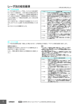
警告
正しい取扱いをしなければ、この危険のために、軽傷・中程度の
傷害を負ったり、万一の場合には重傷や死亡に至る恐れがありま
す。また、同様に重大な物的損害をもたらす恐れがあります。
● 図記号の意味
●レーザ光線
レーザ光線による危害が生じる可能性を示します。
●分解禁止
機器を分解することで、感電などの障害が起こる可能性を示します。
レーザ製品を安全に使用していただくために
レーザ機器に関しては、国内・外でレーザ安全対策が規定されています。国内で使用される場合、
国内にて組付けられて海外輸出される場合、
これらを3つのケースにわけて説明します。
1.国内で使用する場合
JIS C6802規格で、
レーザ製品のクラスに応じて使用者が行わなければならない安全予防対
策が規定されています。
● 警告表示
・形ZX2-LD□□□センサヘッド:クラス2
警告
レーザが直接、
または鏡面の物体に反射して、
目に入らないように
ご注意ください。
レーザから放射されたレーザ光はパワー密度が高
く、
目にはいると失明する恐れがあります。
分解しないでください。分解すると、
レーザ光がもれ出し視力障害を
起こす恐れがあります。
・レーザに関するラベル表示センサヘッド側面
に右図の警告ラベルを貼っています。
警告
レーザ光
ビームをのぞきこまないこと
クラス2レーザ製品
Max. 1.0mW 2.0ms
半導体レーザ 660nm
JIS C 6802 : 2005
クラス分類
クラスの説明
レーザー安全管理者
証明ラベル
クラス2警告/
レーザ放出開口ラベル
Complis with 21 CFR 1040.10 and 1040.11
except for deviations pursuant to Laser
Notice NO.50,dated JUNE 24,2007
OMRON Corporation
リモートインターロック
かぎによる制御
ビーム減衰器
放出標識装置
Shiokoji Horikawa, Shimogyo-ku,
Kyoto 600-8530 JAPAN
Place of manufacture:
AYABE Factory, OMRON Corp.
Manufactured in
警告標識
ビーム光路
鏡面反射
3.米国を除く諸外国へ輸出する場合
■形ZX2-LD□□□センサヘッド
米国以外の地域については、警告説明
ラベルを付属品の英文ラベルに貼替えて
ください。
目の保護
防護着衣
訓練
IEC/EN60825-1:2007
■ヨーロッパへの輸出
EN規格によって、本製品はEN60825-1規格に定めるClass2に分類されます。
2.
センサヘッドの設置について
測定中心
センサヘッドをM3ねじで固定します。締付けトルクは0.3N・mで確実に取り付けてください。
基準面
L
22.6
4
9.7
35.5
2-φ3.2(取り付け穴)
レンジ表示灯
27.5
投光軸
6
投光中心
受光軸
2-R4
基準面
受光部
28.43
15.1
30.3
*形ZX2-LD50(L)の場合
レーザ
警告灯
L=50
ビニール絶縁丸型コード φ4.7 4芯
(導体断面積:0.086mm2/
絶縁体径:φ0.7mm)
標準長さ 0.5m
A=21°
形ZX2-LD100(L)の場合 L=100 A=11.5°
(単位:mm)
投光中心
位置マーク
取りつけ寸法図
(単位:mm)
27.5±0.1
ご使用に際してのご承諾事項
2-M3
重要
・センサヘッドの投光部、受光部には触れないでください。指紋などが付着すると、
正しく測定できなく
なります。誤って触れた場合は、清潔な柔らかい布で汚れを拭き取ってください。
・コネクタ部は振動や衝撃がかからないように固定してください。
使用者への安全予防対策要求の要約
(JIS C 6802:2005規格概要)
※この表は、
便宜上要求事項の要約を示したものです。実際の適用については、必ず規格原文をご確認ください。
・ラベルを貼る位置
IEC/EN60825-1:2007
2.米国へ輸出する場合
本装置を機器に搭載して米国へ輸出す
る場合、米国FDA(Food and Drug
Administrationの規制)
のレーザ規制を
受けます。形ZX2シリーズは、本規格の
Laser Notice NO.50の規定に従い
IEC/EN60825-1の基準にてClass2に
分類され、CDRH (Center for Devices
and Radiological Health)に届出予定
です。警告ラベルをセンサ本体に貼って
ください。
F.S. 測定範囲
(*1)ビーム径:測定中心距離の値。測定中心距離でのTYP.値を示します。中心光強度の1/e2
(13.5%)
で定義。主ビ−ムの周りに漏れ光があり、対象物の周囲の状況によっては、影響が
出る場合があります。
(*2)分解能:アンプに接続した際のアナログ出力のゆらぎ幅
(±3σ)
。
(形ZX2-LDAの応答時間を
128msに設定し、基準ワークを測定中心距離に設定した場合)基準ワーク 白色セラミックス
(*3)リニアリティ
:基準ワーク測定時における変位出力の理想直線に対する誤差。
(*4)温度特性:センサと対象物
(基準ワーク)
の間をアルミの治具で固定した場合の値。
(測定中心
距離で測定)
投光軸
4.8
● 警告表示の意味
製品が動作不能、誤動作、
または性能・機器への悪影響を防ぐため、以下のことを守ってください。
■設置場所について
次のような場所には設置しないでください
・周囲温度が定格の範囲を越える場所
・急激な温度変化により、結露が発生する場所
・相対湿度が35∼85%RHの範囲を超える場所
・腐食性ガス、可燃性ガスがある場所
・塵埃、塩分、鉄粉がある場所
・振動や衝撃が直接加わる場所
・強い外乱光
(レーザ光、
アーク溶接光など)
があたる場所
・直射日光があたる場所や暖房器具のそば
・水・油・化学薬品の飛沫がある場所
・強磁界、強電界がある場所
■電源および配線について
・アンプユニットは、必ず専用アンプユニット
(ZX2-LDA□)
をご使用ください。
・センサヘッドからのコード延長は、10m以内としてください。
また、別売の延長ケーブル
(ZX2-XC□R)
をご使用ください。
■ウォームアップについて
・電源投入後、10分以上経過してからご使用ください。
・電源投入直後は回路が安定していませんので、計測値が徐々に変化することがあります。
■保守点検について
・調整や着脱を行う場合は、必ず電源を切ってから作業をしてください。
・清掃には、
シンナー、
ベンジン、
アセトン、灯油類は使用しないでください。
・センサヘッド前面のフィルタに、大きなゴミやホコリが付いた場合は、
ブロアブラシ(カメラレンズ用)で吹
き飛ばしてください。呼気で吹き飛ばすことは避けてください。小さなゴミやホコリは柔らかい布(レン
ズクリーナーなど)にアルコールを少量含ませて、
ていねいにふき取ってください。強くふくことは避け
てください。
フィルタに傷がつくと、誤差の原因になります。
■対象物について
対象物の材質・形状によって、測定できない場合や精度が出ない場合があります。
(透明な部材、
反射率の極端に小さな材質。
スポット径よりも小さな対象物、曲率の大きな対象物、大きく傾斜した
対象物など)
■相互干渉について
アンプユニット間に演算ユニット
(ZX2-CAL)
を接続して使用することにより、複数台のセンサヘッ
ド間の相互干渉を防止できます。
ただし、1台のセンサヘッドの受光量が上限値に近い状態のとき
に別のセンサヘッドのレーザ光が入光すると、
その効果を発揮できない場合もあります。相互干渉
抑制を目的として演算ユニットを検討される場合は、事前に実機テストで確認してください。
基準面
20.9
安全上のご注意
4.
外形寸法図
4.8
使用上の注意
項目
適用アンプ
ZX2-LDA□
測定中心距離
50mm
100mm
測定範囲
±10mm
±35mm
光源
赤色半導体レーザ
(波長=660nm 1mW以下 JISクラス2)
約115×2,000μm
約φ110μm
ビーム径 *1
約75×2,000μm
約φ70μm
分解能 *2
1.5μm
5μm
リニアリティ 全領域
±0.1%F.S.
±0.15%F.S.
±0.1%F.S.
±0.15%F.S.
*3
±0.05%F.S.
±0.1%F.S.
領域限定 ±0.05%F.S.
±0.1%F.S.
(40∼50mm) (40∼50mm) (65∼100mm)(65∼100mm)
温度特性 *4
0.02%F.S./℃
周囲温度
動作時:0∼50℃ 保存時:−15∼+70℃
(ただし、氷結、結露しないこと)
周囲湿度
動作、保存時:35∼85%RH
(ただし、結露しないこと)
周囲照度
受光面照度 白熱ランプ:10,000ℓx
耐電圧
AC1000V 50∼60Hz 1min.
振動
(耐久)
10∼150Hz 複振幅0.7mm X,Y,Z各方向80min.
(上下、左右、前後)
衝撃(耐久)
300m/s2 6方向各3回
IP67
保護構造
ケース:ポリブチレンテレフタレート、
レンズフィルタ:ガラス、
ケーブル:PVC
材質
本体:約75g、梱包状態:約160g
質量
4
* 2 1 4 7 2 7 9 - 9 B *
100mm以内
ZX2-LD100
39.5
2010 All Rights Reserved.
ZX2-LD100L
47.5
© OMRON Corporation
ZX2-LD50
7
このたびは、本製品をお買い上げいただきまして、まことにありがとうございます。
ご使用に際しては、次の内容をお守りください。
・ 電気の知識を有する専門家がお取り扱いください。
・この取扱説明書をよくお読みになり、十分にご理解のうえ、正しくご使用ください。
・この取扱説明書はいつでも参照できるよう大切に保管してください。
ZX2-LD50L
A°
取扱説明書
形式
9.7
レーザ変位センサ CMOSタイプ センサヘッド
1.
定格/性能
φ12.6
ZX2-LD□□
・センサヘッド 1台 ・フェライ
トコア 1個 ・レーザ警告ラベル
(和文・英文)
各1枚
・取扱説明書
(本書)
1部
10.5
形
以下に示すような項目は安全を確保する上で必要なことですので必ず守ってください。
■設置環境について
・引火性、爆発性ガスの環境では使用しないでください。
・操作や保守の安全を確保するため、高電圧機器や動力機器から離して設置してください。
■電源および配線について
・専用のアンプユニット以外と接続しないでください。
・高圧線、動力線と当製品の配線は別配線としてください。同一配線あるいは同一ダクトにすると誘
導を受け、
誤動作あるいは破損の原因になることがあります。
・コネクタを着脱するときは、
必ず電源を切ってから行ってください。
■設置について
・取付けにおいて、
ねじの締め付けは規定のトルク以下で確実に行ってください。
規定のトルク M3:0.5N・m
■その他
・本体の分解、修理、改造、加圧変形、焼却などは絶対にしないでください。
・廃棄するときは、産業廃棄物として処理してください。
・万が一、異常を感じたときには、
すぐに使用を中止し、電源を切った上で、
当社支店・営業所までご
相談ください。
センサヘッドケーブルには、付属品のフェライ
トコアを必ず取り付けてください。取付位置は、
センサ
ヘッド側100mm以内に1個です。
35.3
スマートセンサ
3.
センサヘッドの接続について
パッケージ内容の確認
39.5±0.1
安全上の要点
クラス1
クラス1M
クラス2
クラス2M
クラス3R
クラス3B
クラス4
まばたき 使用者が光学器具を使用 直接ビーム内観察は危険 直接ビーム内観察は通常 高パワー。拡散反射も
合理的に予測できる条件 使用者が光学器具を使用 低パワー。通常、
した場合に危険になること などの嫌悪反応によって した場合に危険になること になることがある。
危険になることがある。
において危険である。
下で安全である。
があるという点を除いて、 目は保護され安全である。 があるという点を除いて、
クラス2に同じ。
クラス1に同じ。
可視放射の場合には必 必要
必要でないが、
レーザービームの直接観察を伴うアプリケーションの場合に配置することが推奨される。
要でない。非可視放射の
場合には必要である。
部屋又はドア回路に接続する。
不要
使用していないときはかぎを抜いておく。
不要
使用時には不注意な照射を避ける。
不要
レーザーが非可視波長で レーザーが運転されていることを示す。
不要
運転されていることを示す。
警告標識の予防策に従う。
不要
クラス2M
(注1)
について 有効な長さの端でビームを終端する。
クラス1M
(注1)
について 不要
不要
はクラス3Bと同様
はクラス3Bと同様
クラス2M
(注1)
について 意図しない反射を避ける。
クラス1M
(注1)
について 要求事項なし
要求事項なし
はクラス3Rと同様
はクラス3Bと同様
要求事項なし
技術上及び管理上の手順が実行できない場合で
かつMPEを超える場合に必要。
特定の指示が必要
要求事項なし
時には必要
クラス2M
(注1)
について すべての運転員及び保守要員に必要
クラス1M
(注1)
について 要求事項なし
要求事項なし
はクラス3Bと同様
はクラス3Rと同様
注1 測定開口の直径と測定距離の条件1
(注3)
を満たすことができなかったクラス1Mレーザ製品。測定開口の直径と測定距離の条件2を満たすことができなかったクラス1Mレーザ製品には必要でない。
注2 測定開口の直径と測定距離の条件1
(注3)
を満たすことができなかったクラス2Mレーザ製品。測定開口の直径と測定距離の条件2を満たすことができなかったクラス2Mレーザ製品には必要でない。
注3 JIS規格 C6802:2005 表10をご確認ください。
①安全を確保する目的で直接的または間接的に人体を検出する用途に、
本製品を使用し
ないでください。同用途には、
当社センサカタログに掲載している安全センサをご使用く
ださい。
②下記用途に使用される場合、
当社営業担当者までご相談のうえ仕様書などによりご確
認いただくとともに、
定格・性能に対し余裕を持った使い方や、
万一故障があっても危険
を最小にする安全回路などの安全対策を講じてください。
a)屋外の用途、
潜在的な化学的汚染あるいは電気的妨害を被る用途
またはカタログ、
取扱説明書等に記載のない条件や環境での使用
b)原子力制御設備、
焼却設備、
鉄道・航空・車両設備、
医用機械、
娯楽機械、
安全装置、
および行政機関や個別業界の規制に従う設備
c)人命や財産に危険が及びうるシステム・機械・装置
d)ガス、
水道、
電気の供給システムや24時間連続運転システムなどの
高い信頼性が必要な設備
e)その他、
上記 a) ∼ d) に準ずる、
高度な安全性が必要とされる用途
*上記は適合用途の条件の一部です。当社のベスト、
総合カタログ・データシート等最新版
のカタログ、
マニュアルに記載の保証・免責事項の内容をよく読んでご使用ください。
インダストリアルオートメーションビジネスカンパニー ●お問い合わせ先
カスタマサポートセンタ
フリーコール
01 2 0 - 9 19 - 0 6 6
携帯電話・PHSなどではご利用いただけませんので、
その場合は下記電話番号へおかけください。
電話
055-982-5015 (通話料がかかります)
〔技術のお問い合わせ時間〕
■営業時間:8:00∼21:00
■営 業 日:365日
■上記フリ−コ−ル以外のセンシング機器の技術窓口:
電話
055-982-5002
(通話料がかかります)
〔営業のお問い合わせ時間〕
■営業時間:9:00∼12:00/13:00∼17:30 (土・日・祝祭日は休業)
■営 業 日:土・日・祝祭日/春期・夏期・年末年始休暇を除く
●FAXによるお問い合わせは下記をご利用ください。
カスタマサポートセンタ お客様相談室 FAX 055-982-5051
●その他のお問い合わせ先
納期・価格・修理・サンプル・仕様書は貴社のお取引先、
または貴社担当オムロン営業員にご相談ください。
q 2 0 0 9 年 1 0月
PRECAUTIONS ON SAFETY
●Keys to Warning Symbols
WARNING
Indicates a potentially hazardous situation which, if not avoided, will
result in minor or moderate injury,or may result in serious injury or
death. Additionally there may be significant property damage.
●Explanation of signs
●Laser beam
Cautions to indicate potential Laser beam hazard
●Resolution prohibition
Indicates prohibition when there is a risk of minor injury from electrical
shock or other source if the product is disassembled.
●Alert Statements
WARNING
Do not expose your eyes to the laser radiation either directly (i.e., after
reflection from a mirror or shiny surface). Loss of sight may possibly
occur in case of the exposure to laser high power density.
Do not disassemble the product. Doing so may cause the laser beam to
leak,resulting in the danger of visual impairment.
SAFETY PRECAUTIONS FOR USING LASER EQUIPMENT
The ZX2-LD use a laser as the light source. Lasers are classified based on EN
standard (EN 60825-1)
Wavelength
Peak power
Classification
ZX2-LD50/LD50L/LD100/LD100L
660nm
1mW max
Class 2
■Labeling on Laser Use
The ZX2-LD has the following WARNING label
on the side of the sensors.
Max. 1.0mW 2.0ms
半導体レーザ 660nm
JIS C 6802 : 2005
Using in a country other than U.S.
・For countries other than Japan and U.S., warning labels
must be replaced by English ones (supplied with the
product). EN60825-1 is provided for products used in
Europe, and the content of this standard differs.
・The ZX2-LD is categorized as a Class 2 device as
stipulated in EN60825-1:2007.
Replace the warning label with
the corresponding English label
(supplied with the sensor)
Requirements
subclause
Description of
hazard class
Protective housing
Safety interlock in
protective housing
Remote Interlock
IEC/EN60825-1:2007
Manual Reset
IEC/EN60825-1:2007
When using devices in which ZX2-LD is installed
in the U.S., the devices are subjected to the U.S.
FDA (Food and Drug Administration) laser
regulations. ZX2 series is classified into Class2 by
the standard of IEC/EN60825-1 according to
deviations of Laser Notice NO.50 of this standard,
and is scheduled to report to CDRH (Center for
Devices and Radiological Health).
Summary of manufacturer's requirements (EN60825-1:2007)
警告
レーザ光
ビームをのぞきこまないこと
クラス2レーザ製品
Class2 label /
Aperture label
Complis with 21 CFR 1040.10 and 1040.11
except for deviations pursuant to Laser
Notice NO.50,dated JUNE 24,2007
OMRON Corporation
Key control
Emission warning
device
Attenuator
Location controls
Shiokoji Horikawa, Shimogyo-ku,
Kyoto 600-8530 JAPAN
Place of manufacture:
AYABE Factory, OMRON Corp.
Manufactured in
Viewing optics
Scanning
F.S.: Full scale of measurement
(*1)Beam diameter: Measuring center distance. The typical value at the measuring center distance is
shown. Defined as 1/e2 (13.5%) of the center intensity. The beam diameter may sometimes be
affected by the ambient condition of the object such as leaked light fromthe main beam.
(*2)Resolution: Fluctuation width (±3σ) of linear outputs when connected to Amplifier Unit (With response
time set to 128ms and the standard work placed at the measuring center distance) standard work;
white seramics
(*3)Linearity: The error in relation to the ideal displacement output straight line when the standard work
ismeasured
(*4)Temperature characteristic: Value obtained when the sensor and object (standard work) are fixed with
an aluminum jig. (Measured at the measuring center distance)
2.Installing Sensor Heads
Fix the Reflective type sensor head with screws (M3). (tightening torque: M3, 0.3N・m)
Emission
axis mark
Mounting dimensional drawing
(Unit:mm)
27.5±0.1
2-M3
CHECK!
When mounting a Sensor Head, take care not to touch the emitter and receiver.
Adhesion of finger marks may hinder correct measurements. If you have touched them,
wipe them with a clean soft cloth.
Classification
Class 2
Class 2M
Class 3R
Class 3B
Class 4
Direct intrabeam
As for Class 2 except
Direct intrabeam
High power; diffuse
Low power; eye
viewing normally
may be hazardous if
viewing may be
reflections may be
protection normally
hazardous
user employs optics
hazardous
hazardous
afforded by aversion
responses
Required for each laser product; limits access necessary for performance of functions of products
Designed to prevent removal of the panel until accessible emission
Designed to prevent removal of the panel unitil accessible emission values are below that
values are below that for Class 3B or 3Rfor some products
for Class 3R
Permits easy addition of external interlock in
Not required
laser installation
Requires manual reset
Not required
if power interrupted or
remote interlock is
actuated
Laser inoperative when key is removed
Not required
Gives audible or visible warning when laser is switched on or if
Not required
capacitor bank of pulsed laser is being charged. For Class 3R, only
applies if invisible radiation is emitted.
Give means to temporarilly block beam
Not required
Controls so located that there is no danger of exposure to AEL
Not required
abobe Classes 1 or 2 when adjustments are made
Emission from all viewing systems must be below Class 1M AEL
Not required
Scan failure shall not cause product to exceed its classification
Class 1
Safe under reasonably
foreseeable conditions
Class 1M
As for Class 1 except
may be hazardous if
user employs optics
4.Dimensions
Reference plane of detecting distance
Emission axis
Datum level
2-3.2 dia. (mount hole)
Measuring center
L
35.5
Emission 4
axis
27.5
22.6
9.7
Range indicator
6
4.8
Reception axis
Reference plane of
detecting distance
20.9
Emission
point
4.8
© OMRON Corporation 2010 All Rights Reserved.
Please observe the following precautions to prevent failure to operate, malfunctions, or undesirable
effects on product performance.
(1)Do not install the product in locations subjected to the following conditions:
・Ambient temperature outside the rating
・Rapid temperature fluctuations (causing condensation)
・Relative humidity outside the range of 35 to 85%
・Presence of corrosive or flammable gases
・Presence of dust, salt, or iron particles
・Direct vibration or shock
・Reflection of intense light (such as other laser beams, electric arc-welding machines, or
ultra-violet light)
・Direct sunlight or near heaters
・Water, oil, or chemical fumes or spray, or mist atmospheres
・Strong magnetic or electric field
(2)Power Supply and Wiring
・Use only products that have been made expressly for the Controller
・To extend the cable from the sensor head, an optional extension cable(ZX2-XC□R) must be
used.
(3)Warming Up
・After turning on the power supply, allow the Controller to stand for at least 10 minutes before
use. The circuits are unstable immediately after the power supply is turned on and attempting
measurement may result in inconsistent measurement values.
(4)Maintenance and inspection
・Always turn off the power of the unit before connecting or disconnecting cables.
・Do not use thinner, alcohol, benzene, acetone, or kerosene to clean the sensor.
・If considerable foreign matter or dust collects on the front of sensor, use a blower brush (for
camera lenses) to blow off the foreign matter. Avoid blowing it off with your breath. For a small
amount of foreign matter or dust, gently wipe with a soft cloth. Do not wipe hard. If the surface
is damaged, false detection may result.
(5)Sensing Object For Reflective Type Sensor Head
・The product cannot accurately measure the following types of objects:Transparent objects,
objects with an extremely low reflective sensor ratio, objects smaller than the spot diameter,
objects with a large curvature, excessively inclined objects,etc.
(6)Mutual interference
・Inserting a calculation unit between amplifier units can prevent mutual interference between
sensor heads. However, this may not work efficiently if Amount of light received of one sensor
head is saturated because of the luster of work-pieces and a laser beam of the other sensor head
is input. If you are interested in installing a calculation unit in order to prevent mutual
interference, carry out a test using the actual system beforehand.
Item
Applicable Amplifier
ZX2-LDA□
Units
Measuring center
50mm
100mm
distance
±10mm
±35mm
Measuring range
Red semiconductor laser (λ=660nm, 1mW max., EN60825-1 class 2)
Light source
Approx.75×2,000um Approx.70um-dia. Approx.115×2,000um Approx.110um-dia.
Beam diameter (*1)
1.5µm
5µm
Resolution (*2)
±0.1%F.S.
±0.15%F.S.
±0.1%F.S.
±0.15%F.S.
Linearity Full range
Half range ±0.05%F.S.
±0.1%F.S.
±0.05%F.S.
±0.1%F.S.
(*3)
(40-50 mm)
(40-50 mm)
(65-100 mm)
(65-100 mm)
Temperature
0.02%F.S. / ℃
characteristic (*4)
Ambient temperature Operating: 0 to 50℃, Storage: −15 to 70℃ (with no icing or condensation)
Operating and storage: 35% to 85% (with no condensation)
Ambient humidity
Operating ambient
Illuminance on receiving optical side 10,000 lx (incandescent light)
illumination
1,000 VAC, 50/60 Hz for 1 min
Dialectic strength
10 to 150 Hz, 0.7-mm double amplitude,
Vibration resistance
80 min each in X, Y, and Z directions
(destructive)
300 m/s2 3 times each in six directions
Shock resistance
(up/down, left/right, forward/backward)
(destructive)
IP67
Degree of protection
PBT (Case), Glass (Lensfilter), PVC(Cable)
Materials
Approx.160g (sensor head: Approx. 75g)
Weight (packed state)
4
The following notice applies only to products that carry the CE mark:
Notice:
This is a class A product. In residential areas it may cause radio
interference, in which case the user may be required to take adequate
measures to reduce interference.
Within
100mm
ZX2-LD100
39.5
PRECAUTIONS FOR CORRECT USE
ZX2-LD100L
47.5
TRACEABILITY INFORMATION:
Representative in EU:
Manufacturer:
Omron Europe B.V.
Omron Corporation,
Wegalaan 67-69
Shiokoji Horikawa, Shimogyo-ku,
2132 JD Hoofddorp,
Kyoto 600-8530 JAPAN
The Netherlands
Ayabe Factory
3-2 Narutani, Nakayama-cho,
Ayabe-shi, Kyoto 623-0105 JAPAN
ZX2-LD50
7
Thank you for selecting OMRON product. This sheet primarily describes
precautions required in installing and operating the product. Before operating
the product, read the sheet thoroughly to acquire sufficient knowledge of
the product. For your convenience, keep the sheet at your disposal.
Refer to the user’s manual for details.
ZX2-LD50L
A°
INSTRUCTION SHEET
Model
9.7
Laser Displacement Sensor CMOS type
Sensor head unit For Model ZX2-LDA□□
1.Specifications
2-R4
Receptor point
12.6 dia.
ZX2-LD□□
・Sensor head ×1 ・Ferrite core ×1 ・Laser warning label ×1 ・Manual (this paper) ×1
10.5
Model
Please observe the following precautions for safe use of the products.
(1)Installation Environment
・Do not use the product in environments where it can be exposed to inflammable/explosive gas.
・To secure the safety of operation and maintenance, do not install the product close to
high-voltage devices and power devices.
(2)Power Supply and Wiring
・Use only products that have been made expressly for the Controller
・High-Voltage lines and power lines must be wired separately from this product. Wiring them
together or placing them in the same duct may cause induction, resulting in malfunction or
damage.
・Always turn off the power of the unit before connecting or disconnecting cables.
(3)Installation
・Make sure to tighten all installation screws securely.(tightening torque: M3, 0.5N・m )
(4)Other Rules
・Do not attempt to disassemble, deform by pressure, incinerate, repair, or modify this product.
・When disposing of the product, treat as industrial waste.
・If you notice an abnormal condition such as a strange odor, extreme heating of the unit, or
smoke, immediately stop using the product, turn off the power, and consult your dealer.
3.Sensor connections
A ferrite core (supplied with the sensor head) must be attached to the sensor cable. The ferrite
cores can be connected within 100 mm from the sensor.
35.3
Smart Sensor
Checking the package contents
39.5±0.1
PRECAUTIONS FOR SAFE USE
15.1
30.3
*For ZX2-LD50(L)
For ZX2-LD100(L)
L=50
Laser
warning
indicator
28.43
A=21°
L=100 A=11.5°
Round vinyl insulated cable
4.7 dia. 4-wire code
(Conductor cross sectional area: 0.086mm2 /
Insulation outside diameter: 0.7mm dia.)
Standard length 0.5m
(UNIT:mm)
Suitability for Use
THE PRODUCTS CONTAINED IN THIS SHEET ARE NOT SAFETY RATED.
THEY ARE NOT DESIGNED OR RATED FOR ENSURING SAFETY OF
PERSONS, AND SHOULD NOT BE RELIED UPON AS A SAFETY
COMPONENT OR PROTECTIVE DEVICE FOR SUCH PURPOSES.
Please refer to separate catalogs for OMRON's safety rated products.
OMRON shall not be responsible for conformity with any standards, codes, or
regulations that apply to the combination of the products in the customer's
application or use of the product.
Take all necessary steps to determine the suitability of the product for the
systems, machines, and equipment with which it will be used.
Know and observe all prohibitions of use applicable to this product.
NEVER USE THE PRODUCTS FOR AN APPLICATION INVOLVING
SERIOUS RISK TO LIFE OR PROPERTY WITHOUT ENSURING THAT THE
SYSTEM AS A WHOLE HAS BEEN DESIGNED TO ADDRESS THE RISKS,
AND THAT THE OMRON PRODUCT IS PROPERLY RATED AND
INSTALLED FOR THE INTENDED USE WITHIN THE OVERALL
EQUIPMENT OR SYSTEM.
See also Product catalog for Warranty and Limitation of Liability.
EUROPE
OMRON EUROPE B.V. Sensor Business Unit
Carl-Benz Str.4, D-71154 Nufringen Germany
Phone:49-7032-811-0 Fax: 49-7032-811-199
NORTH AMERICA
OMRON ELECTRONICS LLC
One Commerce Drive Schaumburg,IL 60173-5302 U.S.A.
Phone:1-847-843-7900 Fax : 1-847-843-7787
ASIA-PACIFIC
OMRON ASIA PACIFIC PTE. LTD.
No. 438A Alexandra Road #05-05-08(Lobby 2),
Alexandra Technopark, Singapore 119967
Phone : 65-6835-3011 Fax :65-6835-2711
CHINA
OMRON(CHINA) CO., LTD.
Room 2211, Bank of China Tower,
200 Yin Cheng Zhong Road,
PuDong New Area, Shanghai, 200120, China
Phone : 86-21-5037-2222 Fax :86-21-5037-2200
OMRON Corporation
o
O C T, 2 0 0 9