1
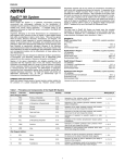
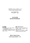
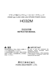
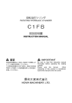
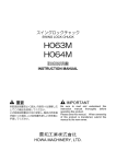
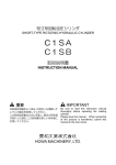
回転エアーシリンダ
ROTATING AIR CYLINDER
H05CH
H05CHB
取扱説明書
INSTRUCTION MANUAL
重要
IMPORTANT
本取扱説明書をよく読み,内容を十分理解した
上でこの製品を使用してください。
この取扱説明書は大切に保管し,製品の所有者
が変わった場合,この説明書も新しい所有者に
手渡してください。
Be sure to read this instruction manual
thoroughly before operating the rotating
cylinder.
Please save this manual. When ownership
of this product is transferred, submit this
manual to the new owner.
豊和工業株式会社
HOWA MACHINERY, LTD.
目
はじめに
次
・・・・・・・・・・・・・・・・・・・・・・・・・・・・・・・・・・・・・・・・・・・・・・・・・・・・・・ 1
安全についてのインフォメーション
安全のために
・・・・・・・・・・・・・・・・・・・・・・・・・・・・・・ 1
・・・・・・・・・・・・・・・・・・・・・・・・・・・・・・・・・・・・・・・・・・・・・・・・・・ 2
1.構造と作動
1.1 形番表示
・・・・・・・・・・・・・・・・・・・・・・・・・・・・・・・・・・・・・・・・・・・・・・・ 4
1.2 構造と作動 ・・・・・・・・・・・・・・・・・・・・・・・・・・・・・・・・・・・・・・・・・・・・・・・ 4
2.仕様
・・・・・・・・・・・・・・・・・・・・・・・・・・・・・・・・・・・・・・・・・・・・・・・・・・・・・・ 6
3.取付け方法
3.1 シリンダアダプタ
・・・・・・・・・・・・・・・・・・・・・・・・・・・・・・・・・・・・・・・ 8
3.2 コネクチングロッド
3.3 取付け・回り止め
3.4 配管
・・・・・・・・・・・・・・・・・・・・・・・・・・・・・・・・・・・・・・ 10
・・・・・・・・・・・・・・・・・・・・・・・・・・・・・・・・・・・・・・・・・・・・・・・・・・ 11
3.5 圧縮空気
・・・・・・・・・・・・・・・・・・・・・・・・・・・・・・・・・・・・・・・・・・・・・・ 11
3.6 ストローク規制
3.7 試運転
・・・・・・・・・・・・・・・・・・・・・・・・・・・・・・・・・・・・・ 9
・・・・・・・・・・・・・・・・・・・・・・・・・・・・・・・・・・・・・・・・ 12
・・・・・・・・・・・・・・・・・・・・・・・・・・・・・・・・・・・・・・・・・・・・・・・・ 12
4.保守・点検
4.1 潤滑油の点検
・・・・・・・・・・・・・・・・・・・・・・・・・・・・・・・・・・・・・・・・・・ 12
4.2 分解・パーツリスト
限定保証
・・・・・・・・・・・・・・・・・・・・・・・・・・・・・・・・・・・・ 12
・・・・・・・・・・・・・・・・・・・・・・・・・・・・・・・・・・・・・・・・・・・・・・・・・・・・・ 15
はじめに
1. この取扱説明書は,H05CH 形,H05CHB 形回転エアーシリンダの標準形について説明しています。
2. この回転シリンダをご使用いただく前に,必ずこの取扱説明書を熟読し,取付け・運転・点検・保守について十
分に理解した上でご使用くださるようお願いします。
3. この取扱説明書の記載事項を守らない場合,作業者や周りの人を巻き込んだ重大な事故や機械の破損に結びつく
事があります。
4. この取扱説明書は常に手元に置き,紛失しないように大切に保管してください。
5. この取扱説明書と,この取扱説明書が対象とする製品についての問い合わせは下記へお願いします。
またこの取扱説明書を紛失したときも下記へ直接請求してください。
豊和工業株式会社 機械事業部 産業機器グループ
産業機器グループ
〒452-8601 愛知県清須市須ケ口 1900 番地 1
TEL (052)408-1254
FAX (052)409-3766
6. この取扱説明書は SI 単位で書かれています。 従来単位による数値は以下の式で求めることができます。
圧 力
1MPa=10.197kgf/cm2
トルク
1N・m=0.10197kgf・m
安全についてのインフォメーション
この製品を安全にご使用していただくために必要な警告事項を,安全警告シンボルと共に記載してあります。 警告
事項を良く読み,十分に理解してください。
この取扱説明書の警告メッセージをより良く理解していただくために,警告シンボルを次のように使い分けてあり
ます。
危険
警告
注意
この表示
この表示は
表示は,取扱いを
取扱いを誤
いを誤った場合
った場合に
場合に,重傷もしくは
重傷もしくは死
もしくは死に至る危険が
危険が切迫して
切迫して生
して生じることが想
じることが想
定される事項
される事項を
事項を示します。
します。
これらの警告
これらの警告メッセージ
危険を回避するのに
回避するのに講
じなければならない予防措置が
警告メッセージには
メッセージには,
には,危険を
するのに講じなければならない予防措置
予防措置が含まれ
ます。
ます。
この表示
この表示は
表示は,取扱いを
取扱いを誤
いを誤った場合
った場合に
場合に,重傷もしくは
重傷もしくは死
もしくは死に至る可能性が
可能性が想定される
想定される事項
される事項を
事項を示し
ます。
ます。
これらの警告
これらの警告メッセージ
危険を回避するのに
回避するのに講
じなければならない予防措置が
警告メッセージには
メッセージには,
には,危険を
するのに講じなければならない予防措置
予防措置が含まれ
ます。
ます。
この表示
この表示は
表示は,取扱いを
取扱いを誤
いを誤った場合
った場合に
場合に,軽微な
軽微なケガの
ケガの発生または
発生または機械
または機械の
機械の損傷が
損傷が想定される
想定される状態
される状態
を示します。
します。
当社は,あらゆる環境下における運転・操作・点検・保守のすべての危険を予測することはできません。 そのため,
この取扱説明書に明記されている警告は,安全のすべてを網羅したものではありません。
また,
「できないこと」や「してはいけないこと」は極めて多くあり,この取扱説明書にすべて書く事はできません。
この取扱説明書に「できる」と書いてない限り,「できない」と考えてください。 もし,この取扱説明書に書かれ
ていない運転・操作・点検・保守を行う場合,安全に対する必要な配慮は,すべて自分の責任でお考え願います。
-1-
安全のために
ご使用の前に特に知っておいていただきたいこと,守っていただきたいことをまとめています。 必ずお読みくださ
い。
危険
スピンドル回転中
スピンドル回転中は
回転中は,空気圧の
空気圧の供給を
供給を止めてはいけない。
めてはいけない。
把握したワークが飛散し危険です。
スピンドル回転中
スピンドル回転中は
回転中は,切換弁の
切換弁の操作を
操作を行ってはならない。
ってはならない。
把握したワークが飛散し危険です。
スピンドル回転中
スピンドル回転中は
回転中は,スピンドルカバーの
スピンドルカバーの中に体の一部を
一部を入れて
はならない。
はならない。
回転物に巻き込まれ危険です。
電磁弁は
電磁弁は,無通電時把握する
無通電時把握する回路
する回路とすること
回路とすること。
とすること。
把握したワークが飛散し危険です。
把握中は
把握中は,空気圧力を
空気圧力を一定に
一定に保つこと。
つこと。
把握したワークが飛散し危険です。
警告
回転シリンダ
回転シリンダの
シリンダの取付け
取付け・点検・
点検・保守の
保守の時には,
には,電源を
電源を切ること。
ること。
回転物に巻き込まれ危険です。
回転シリンダ
回転シリンダの
シリンダの外周には
外周にはカバー
にはカバーを
カバーを付けること。
けること。
回転物に巻き込まれ危険です。
スピンドル回転中
スピンドル回転中は
回転中は,スピンドルカバーを
スピンドルカバーを開いてはならない。
いてはならない。
回転シリンダが焼付いた時,部品が飛散し危険です。
使用回転数は
使用回転数は,回転シリンダ
回転シリンダおよび
シリンダおよびチャック
およびチャックの
チャックの最高使用回転数の
最高使用回転数の
範囲内で
範囲内で使用すること
使用すること。
すること。
破損,焼付きの原因となります。
落したり叩
したり叩いたりして衝撃
いたりして衝撃を
衝撃を与えないこと。
えないこと。
破損,焼付きの原因となります。
-2-
警告
取付け
取付けボルトの
ボルトの締付けは
締付けは確実
けは確実に
確実に行うこと。
うこと。
指定の締付けトルクを守らないと,ボルトの緩み,ボルトの破損により
部品,ワークの飛散が発生するおそれがあります。
ボルトのサイズと締付けトルクを下表に示します。
ボルトサイズ
M10
M12
締付けトルク (N・m)
57.9
101
M16
161
使用空気圧力は
使用空気圧力はチャックの
チャックの仕様に
仕様に合わせること。
わせること。
ただし回転
ただし回転シリンダ
回転シリンダの
シリンダの最高使用圧力を
最高使用圧力を超えてはならない。
えてはならない。
過大な圧力を加えると回転シリンダ,またはチャックが破損するおそれ
があります。
コネクチングロッドは
コネクチングロッドは,ねじ部
ねじ部に接着剤を
接着剤を塗布し
塗布し,適正な
適正なトルク
で締付けること
締付けること。
けること。
ねじが緩むとチャックのジョーストロークが短くなり,ワーク飛散の原
因となります。
接着剤:スリーボンド 1344 相当品を使用してください。
コネクチングロッドの締付けトルクを下表に示します。
ボルトサイズ
M12
M16
M20
締付けトルク (N・m)
25
61
117
M24
209
M27
285
空気圧供給ライン
空気圧供給ラインには
ラインにはフィルタ
にはフィルタを
フィルタを組込むこと
組込むこと。
むこと。
回転シリンダ内に異物が混入すると,焼付きの原因となります。
5μm以下のフィルタを圧力供給ラインに組込んでください。
空気圧と
空気圧と共に潤滑油を
潤滑油を供給すること
供給すること。
すること。
適切に潤滑された空気を使用しないと,焼付きの原因となります。
ISO VG32 相当の潤滑油を供給してください。
消耗品を
消耗品を含むすべての部品
むすべての部品は
部品は豊和工業へ
豊和工業へ注文してください
注文してください。
してください。
豊和工業が扱う以外の部品を用いて発生する事故については,その責を
負いかねます。 また豊和工業の純正部品を用いない限り,すべての保
証は無効になります。
注意
回転シリンダ
回転シリンダの
シリンダの取付け
取付け,取外しの
取外しの時
しの時,吊りベルトを
ベルトを使用すること
使用すること。
すること。
手を滑らして回転シリンダを落したり,腰をいためたりするおそれがあ
ります。
-3-
1.構造と
構造と作動
1.1 形番表示
H05CH/H05CHB 形回転エアーシリンダは次のように分類されます。
H05CH
サイズ
100・
100・150・
150・175・
175・200・
200・250・
250・300
無 :逆止弁なし
B :逆止弁付き
1.2
1.2 構造と
構造と作動
H05CH/H05CHB 形回転エアーシリンダは,大きく分けてシリンダ,ピストン,ディストリビュータより構成さ
れており,ディストリビュータから供給された空気圧によってシリンダ内をピストンが軸方向に移動します。そし
てピストンの右端に設けたねじ部にコネクチングロッドを接続することにより,この軸方向の動きをチャックに伝
え,トップジョーの開閉とワークの把握を行います。
ディストリビュータ部は,シリンダとともに回転するディストリビュータシャフトと,回転しないディストリビュ
ータハウジングから成っており,その隙間から漏れた空気はベアリングの冷却と潤滑に使われた後,排気ポートか
ら排出されます。
このように排気ポートから排気される空気の量と,圧力の加わっているポートからもう一方のポートへ短絡する空
気の量の合計を空気漏洩量と呼んでおり,仕様表に書かれたこの値は,コンプレッサの容量を決める上で必要にな
ってきます。
H05CHB 形回転エアーシリンダは逆止弁を内蔵していますから,回転中に空圧系統に事故が起きても,内部圧力
の急激な低下が阻止されます。逆止弁は,シリンダとともに回転するディストリビュータシャフトの中に組込まれ
ていますから,排気ポートからの漏れにかかわりなく内圧を保持することができます。
-4-
H05CH 形
H05CHB 形
-5-
2.仕様
・仕様
形式番号
項目
ピストン面積
150
175
200
250
300
cm2
77.0
175.0
238.7
311.0
486.0
701.9
引側
2
73.0
170.0
231.7
301.4
473.4
689.3
20
25
35
cm
mm
最高使用回転数
r/min
最高使用圧力
質
100
押側
ピストンストローク
慣性モーメント
H05CH
15
6500
5500
4500
MPa
kg・m2
注1
量
kg
空気漏洩量
L/s
3500
0.8
0.010
0.040
0.055
0.090
0.22
0.53
4.4
8.9
10.4
14.5
25.5
38
0.40
0.55
注 1:この数値の 4 倍が GD2 に相当します。
形式番号
記号
A
B
C
D
E
F
G
H
J
K
L
深さ
M1
M2
M4
M5
N
P
Q
T
U
内径
h7
Max.
Min.
H05CH
100
150
175
200
250
300
100
130
105
80
65
22.4
32
17
7
80
102
M10×1.5
17
M12×1.75
25
19
9
1/4
42
20
60
15
150
186
160
130
110
25
34
19
9
88
102
M10×1.5
17
M16×2
38
22
12
1/4
42
20
60
15
175
210
160
130
110
30
34
19
9
88
102
M10×1.5
17
M16×2
38
26
15
1/4
42
20
60
15
200
234
160
130
110
35
54
34
9
98
102
M10×1.5
19
M20×2.5
52
32
18
1/4
42
20
60
15
250
290
160
130
110
40
59
34
9
118
125
M12×1.75
23
M24×3
55
36
18
3/8
48
28
60
20
300
340
235
200
165
40
69
34
9
138
120
M16×2
27
M27×3
55
36
18
3/8
43
28
60
20
-6-
形式番号
項目
ピストン面積
慣性モーメント
質
150
175
200
250
300
cm2
77.0
175.0
238.7
311.0
486.0
701.9
引側
2
73.0
170.0
231.7
301.4
473.4
689.3
20
25
35
cm
mm
r/min
最高使用圧力
100
押側
ピストンストローク
最高使用回転数
H05CHB
15
6500
5500
4500
0.8
MPa
注1
kg・m2
量
kg
空気漏洩量
3500
0.013
0.043
0.058
0.093
0.22
0.53
6.3
10.6
12.1
16.2
28.4
40.9
0.40
L/s
0.55
注 1:この数値の 4 倍が GD2 に相当します。
形式番号
記号
H05CHB
100
A
B
C
D
E
F
G
H
J
K
L
深さ
M1
M2
M4
M5
N
P
Q
T
U
内径
h7
Max.
Min.
150
100
150
130
186
105
160
80
130
65
110
22.4
25
32
34
17
19
7
9
80
88
137
133
M10×1.5 M10×1.5
17
17
M12×1.75 M16×2
25
38
19
22
9
12
1/4
1/4
77
73
20
20
59.5
59.5
15
15
-7-
175
200
250
300
175
210
160
130
110
30
34
19
9
88
133
M10×1.5
17
M16×2
38
26
15
1/4
73
20
59.5
15
200
234
160
130
110
35
54
34
9
98
133
M10×1.5
19
M20×2.5
52
32
18
1/4
73
20
59.5
15
250
290
160
130
110
40
59
34
9
118
159
M12×1.75
23
M24×3
55
36
18
3/8
82
28
60
20
300
340
235
200
165
40
69
34
9
138
120
M16×2
27
M27×3
55
36
18
3/8
77
28
60
20
3.取付け
取付け方法
回転シリンダを取付けるスピンドル後端の形状は,規格統一がされておらず千差万別であるのが実情ですから,最
も代表的な形状を一例として取上げます。
3.1 シリンダアダプタ
回転シリンダの取付け位置は旋盤本体との干渉,配管の方向や位置,通風などを考慮して決めなければなりません。
回転シリンダには,スピンドルの起動,停止,振動による慣性力およびシリンダ出力が加わりますから,これに耐
え得るよう十分な剛性を持ったシリンダアダプタを設計する必要があります。
注意
シリンダアダプタは,面振れおよびインロの振れが 0.005mm 以下となるようにスピンドル
に取付けてください。 振れが大きいと振動の原因になります。
また,ねじ部の緩みを防止するため,セットスクリュを設けてください。
回転シリンダ取付け時の振れを修正できるように,回転シリンダ取付け用インロ部の寸法公差は F7 で製作してく
ださい。
また,回転シリンダの不つり合いは高度に調整してありますから,これを損なわないようシリンダアダプタのバラ
ンスには十分の注意を払ってください。
-8-
3.2 コネクチングロッド
回転シリンダの出力はコネクチングロッドを介してチャックに伝えられ,爪の開閉とワークの把握を行います。
コネクチングロッドをピストンにあらかじめねじ込んでから,回転シリンダを取付け,その後チャックを取付けま
す。
コネクチングロッドは最大推力(ピストン面積×最高使用空気圧力)に十分耐えられる強度が必要です。
警告
コネクチングロッドは,ピストンとコネクチングロッドのねじ部を十分脱脂した後,コネクチ
ングロッドのねじ部に接着剤を塗り,適正なトルクで締付けます。
接着剤:スリーボンド 1344 相当品を使用してください。
コネクチングロッドの締付けトルクを下表に示します。
ボルトサイズ
M12
M16
M20
締付けトルク (N・m)
25
61
117
M24
209
M27
285
コネクチングロッドには回転シリンダとの結合部付近にレンチフラットを設けておき,これを利用してピストンロ
ッドに締付けます。
注意
回転シリンダの回り止めは,ピストンロッドに設けたレンチフラットにスパナを掛けて行って
ください。 シリンダボデー自体を固定してコネクチングロッドを締付けると,締付け力のた
めに内部の部品を破損することがあります。
コネクチングロッドのピストンロッドに対する締付け面の振れはコネクチングロッドの過度の傾斜を防ぐために
0.020mmT.I.R.以内としてください。
また,コネクチングロッドの自重による傾斜や振動を防止するためには,スピンドルのチャック取付け部近くに図
示のようなカラーを取付けると有効です。
-9-
3.3
3.3 取付け
取付け・回り止め
回転シリンダを取付ける上で大切なことは,回転シリンダに無理な力が加わらないようにすることです。
注意
回転エアーシリンダは,高速で回転させるとベアリングの抵抗のためにディストリビュータに
多少のトルクが生じます。
このトルクによって生じる力を受けるために,配管材に鋼管を用いたり,ディストリビュータ
を旋盤の一部へ固定したりすると,回転シリンダ全体に無理な力が加わり,故障や振動の原因
になります。
ですから,配管材にはフレキシブルホースを使用し,ディストリビュータの回り止めには図示
のような余裕のあるフォークを用いてください。
回転シリンダ取付け時の振れは,シリンダ外周で 0.015mm T.I.R. 以下としてください。
警告
回転シリンダの取付けボルトは確実に締付けてください。
ボルトのサイズと締付けトルクを下表に示します。
ボルトサイズ
M10
M12
締付けトルク (N・m)
57.9
101
-10-
M16
161
3.4
3.4 配管
回転シリンダのディストリビュータ部には,Rc1/4 または Rc3/8 の空気圧供給ポートが 2 ヶ所と,シリンダ寄
りに M5 の排気ポートが 1 ヶ所あります。
排気ポートからは通常,仕様表に示す空気が漏れるだけですが,圧縮空気の状態によっては油の混入した水滴が落
ちる場合がありますから水分が悪い影響を及ぼさない場所まで配管しておいてください。
空気圧供給ポートの近くには,そのポートに空気を供給したときに作動するロッドの方向が矢印で刻印してありま
す。
警告
空気圧回路は,配管内のゴミを完全に取除いてから組付けてください。 配管内にゴミが入る
と,回転シリンダ焼付きの原因となります。 また,回転シリンダの性能を保持するために,
必ず 5μm以下のフィルタを圧力供給ラインに組込んでください。
3.5
3.5 圧縮空気
ピストンを必要な速度で作動させるには十分な容量を持つコンプレッサと配管径および空気調質機器を組み合わせ
なければなりません。
必要な空気供給量の計算方法は以下の通りです。
Q:必要な空気供給量…………………………………………………………………(L/min)[A.N.R.]
q:ピストン1往復に要する空気消費量……………………………………………(L)[A.N.R.]
t:加工サイクルタイム(ワークの取付けより切削後取外しまでの時間) …・(min)
a:ディストリビュータの空気漏れ量………………………………………………(L/min)[A.N.R.]
P:使用空気圧力……………………………………………………………………・・(MPa)
N:同時に使用するシリンダの数
①1台使用のとき
②数台使用のとき
Q>
q
+ a + 10
t
q
Q >N × ( + a + 10)
t
(算出例)H05CH200 形を1台使用する場合
仕様表から
ストローク……20 ㎜(=2cm)
引側受圧面積……301.4 cm2
空気漏洩量……0.4 L/sec [A.N.R.]
押側受圧面積……311.0 cm2
P=0.5 MPa t=2 min とする
0.5 + 0.1013
1
q=(301.4×2+311.0×2)×
×
=7.3 (L)[A.N.R.]
0.1013
1000
a=0.4×60=24.0 (L/min)[A.N.R.]
①式より
Q=
7.3
+24.0+10=37.7 (L/min)[A.N.R.]
2
回転エアーシリンダにおいて,圧縮空気は必要な速度でピストンを作動させるだけでなく,ベアリングの冷却と潤
滑の役割があります。清浄で適切に潤滑された空気を用いないと,各部の摩耗を促進し製品の寿命を著しく縮める
結果となることがあります。
エアーフィルタのろ過度は5μm以下、潤滑油種は ISO VG32 相当のものをご使用ください。
推奨油種
ダフニースーパーマルチオイル 32
ダイヤモンドルブ RO32
モービル DTE(ライト)
シェルテラスオイル 32
エッソテレッソ 32
-11-
3.6
3.6 ストローク規制
ストローク規制
チャックのプランジャストロークが回転シリンダのストロークよりも短い場合,チャックのプランジャストローク
に合わせて回転シリンダのストロークを規制する場合があります。
実施に当たっては当社にお問合せください。
3.7
3.7 試運転
① 念のために各取付けボルトが緩んでいないか点検してください。
② 空気圧力 0.1~0.2MPa でシリンダの動作を確かめ作動に異常がないか確認します。 その後,徐々に最高使用
圧力まで上昇させ,各部のエアー漏れや異常がないか調べます。
③ スピンドルを 200~300r/min で回転させ,各部の振動や異音に注意しながら徐々に回転数を上昇させます。
警告
スピンドル回転中は,回転部に不注意に体を近付けたり,回転部に触れたりしないように十分
注意してください。
4.保守・
保守・点検
4.1 潤滑油の
潤滑油の点検
ベアリングの冷却と潤滑は空気と空気に混入させた潤滑油によって行われますから,ルブリケータの油面とエアー
フィルタの汚染状態には常に注意してください。
ルブリケータとエアーフィルタの点検方法についてはメーカの取扱説明書に従ってください。
4.2 分解・
分解・パーツリスト
回転シリンダは,正しく取付けて清浄で適切に潤滑油を混入させた空気を使用していれば,きわめて長い寿命を保
つことができます。 しかし,もし何らかの原因で故障が生じた場合には,分解して必要に応じて部品を交換しなけ
ればなりません。
注意
回転シリンダのシールや構成部品をピストン作動回数 25 万往復毎に細部まで分解点検し,シ
ールの摩耗や部品の損傷がある場合は交換してください。
☆シリンダ内部の圧力抜き
H05CHB 形は逆止弁付のため,分解の前に次の手順でシリンダ内部の圧力を抜いてください。
① 供給する空気圧力を下げながらシリンダを動作させます。
② プラグ(A)を外して内部に封入された圧力を抜きます。
-12-
☆シリンダ本体部の分解
① 取付けボルトを外してロッドカバー(B)をシリンダ(C)から外します。
② ピストン(D)を抜き出します。
☆ディストリビュータの分解
ディストリビュータ部は,シリンダ本体を機械から外すことなく取外すこともできますが,作業の前には必ずシリ
ンダ内部の圧力を抜いてください。
① 取付けボルトを外してディストリビュータアッセンブリ(E)をシリンダ(C)から引き抜きます。
② 取付けボルトを外してエンドカバー(F)を外します。
③ 軸止め輪(G)を外します。
④ プーリ抜きを使用して,ディストリビュータハウジング(H)をベアリング(7),
(8)と共に抜き出します。
☆チェックバルブの分解
① 取付けボルトを外してカバー(I)を,移動させて外します。
② エンドキャップ(J)を押して,反対側のエンドキャップ(K)を押し出します。
③ チェックバルブボデー(L)を押して,エンドキャップ(J)とチェックバルブボデー(L)を押し出します。
④ 軸止め輪(M)を外してバルブ(N)を,チェックバルブボデー(L)から引抜きます。
☆組付け時の注意
各部品には,ゴミが付着しないように注意して,グリースを十分塗布しながら組付けを行ってください。
H05CH 形
-13-
H05CHB 形
☆パーツリスト
H05CH ・ H05CHB
番号
1
2
3
4
5
6
7
8
9
10
11
12
部品名称
PNY パッキン
Oリング
Oリング
Oリング
Oリング
Oリング
ボールベアリング
ボールベアリング
Oリング
Oリング
Oリング
Oリング
100
150
175
PNY-22.4 PNY-25 PNY-30
P14
P15
G30
G35
P90
P140
P160
AS568
G95
G145
-165
S11.2 (NOK)
60/22 LLU
6004UU P6
P7
P18
S12 (NOK)
S20 (NOK)
注1,※印の部品は H05CHB 形にのみ使用しています。
-14-
200
PNY-35
P20
P185
AS568
-169
250
300
PNY-40
P25
G45
P235
P285
AS568
AS568
-177
-277
S15 (NOK)
6005UU P6
6005UU P6
P9
P21
S14 (NOK)
S22 (NOK)
個数
1
1
1
1
1
2
1
1
2 ※
3 ※
2 ※
2 ※
限 定 保 証
売り主は製品が,頒布されている仕様条件に従って製造されたもので,材料上および/または仕上げ上欠
陥がないことを保証いたします。
売り主は,工場へ元のまま返品された運送費前払いのもので,売り主が点検して材料および/または仕上
げに欠陥があると判断した製品は,売り主の自由意志で,修理もしくは交換をいたします。 前記のものに
ついては,それが売り主の保証違反に対する唯一の救済となるものとします。
売り主は,これに限定
これに限定されるわけではありませんが
限定されるわけではありませんが,
されるわけではありませんが,市場性や
市場性や市販性に
市販性に関する保証
する保証,
保証,特定の
特定の目的または
目的または用
または用
途に関する保証
する保証,
保証,もしくは特許侵害
もしくは特許侵害に
特許侵害に対する保証
する保証など
保証など本保証条件以外
など本保証条件以外のものは
本保証条件以外のものは,
のものは,明示の
明示の保証であろうと
保証であろうと黙示
であろうと黙示
の保証であろうと
保証であろうと,
であろうと,なんらの保証
なんらの保証もいたしません
保証もいたしません。
もいたしません。売り主は,いかなる直接的損害
いかなる直接的損害,
直接的損害,付帯的もしくは
付帯的もしくは間接的
もしくは間接的
な損害金,
損害金,あるいは欠陥製品
あるいは欠陥製品もしくは
欠陥製品もしくは製品
もしくは製品の
製品の使用に
使用に起因する
起因する損害金
する損害金または
損害金または費用
または費用については
費用については,
については,なんら責任
なんら責任はな
責任はな
いものといたします。
いものといたします。
-15-
Table of Contents
Precautions ・・・・・・・・・・・・・・・・・・・・・・・・・・・・・・・・・・・・・・・・・・・ 1
For Safe Operation ・・・・・・・・・・・・・・・・・・・・・・・・・・・・・・・・・・・・・ 1
Safety Precautions ・・・・・・・・・・・・・・・・・・・・・・・・・・・・・・・・・・・・・ 2
1. Construction and Operation
1.1 Model Coding ・・・・・・・・・・・・・・・・・・・・・・・・・・・・・・・・・・・・ 4
1.2 Construction and Operation ・・・・・・・・・・・・・・・・・・・・・・・・ 4
2. Specifications ・・・・・・・・・・・・・・・・・・・・・・・・・・・・・・・・・・・・・・・ 6
3. Installation
3.1 Cylinder Adaptor ・・・・・・・・・・・・・・・・・・・・・・・・・・・・・・・・・ 8
3.2 Connecting Rod ・・・・・・・・・・・・・・・・・・・・・・・・・・・・・・・・ 9
3.3 Mounting and Anti-rolling Guide ・・・・・・・・・・・・・・・・・・・ 10
3.4 Piping ・・・・・・・・・・・・・・・・・・・・・・・・・・・・・・・・・・・・・・・・・・ 11
3.5 Compressed Air ・・・・・・・・・・・・・・・・・・・・・・・・・・・・・・・・・ 11
3.7 Stroke Control ・・・・・・・・・・・・・・・・・・・・・・・・・・・・・・・・・・ 12
3.8 Trial Operation ・・・・・・・・・・・・・・・・・・・・・・・・・・・・・・・・・・ 12
4. Maintenance and Inspection
4.1 Check of Lubricating Oil ・・・・・・・・・・・・・・・・・・・・・・・・・・ 12
4.2 Overhaul and Parts List ・・・・・・・・・・・・・・・・・・・・・・・・・・ 12
LIMITED WARRANTY ・・・・・・・・・・・・・・・・・・・・・・・・・・・・・・・・・ 15
Precautions
1. This instruction manual describes model H05CH/H05CHB Rotating Air Cylinder Standard
Model.
2. Please read this manual carefully and fully understand the procedures for installation,
operation, inspection, and maintenance before operating the rotating cylinder.
3. Ignoring any instructions in this manual may result in a serious accident or machine damage,
leading to injury to the operator or personnel near the machine.
4. Please save this manual and keep it handy at all times.
5. Please contact us (phone and fax numbers are shown below) for information regarding this
manual and the objective product. Another copy of this manual is also available from the
following address:
HOWA MACHINERY, LTD.
INDUSTRIAL EQUIPMENT GROUP
MACHINERY DIVISION
1900-1, SUKAGUCHI, KIYOSU, AICHI, 452-8601 JAPAN
Phone :
International access code-81-052-408-1254
Facsimile:
International access code-81-052-409-3766
6. The values of this manual are described in SI unit system.
be obtained by following calculations.
Pressure 1MPa=10.197kgf/cm2
Torque
1N・m=0.10197kgf・m
Values of former unit system can
For Safe Operation
This manual contains warning messages for safe operation that are indicated by Safety Alert
Symbols. Carefully read and fully understand these messages.
The danger levels of the Safety Alert Symbols are defined below.
DANGER
Indicates an imminently hazardous situation which, if not avoided, will
result in death or serious injury. These warning massages include the
preventive actions those are indispensable to avoid danger.
WARNING
Indicates a potentially hazardous situation which, if not avoided, could
result in death or serious injury. These warning massages include the
preventive actions those are indispensable to avoid danger.
CAUTION
Indicates a potentially hazardous situation which, if not avoided, could
result in minor injury or machine damage.
It is impossible to predict all hazardous situations that may occur during operation, inspection,
and maintenance of the rotating cylinder under various circumstances.
Accordingly, the warning messages described in this manual do not cover all hazardous
situations.
Also, there are too many operations that cannot or should not be performed using the rotating
cylinder to be completely described in this manual.
We cannot assume any responsibility for damage or accidents caused through operation,
inspection, or maintenance of the rotating cylinder that is not specified in this manual.
-1-
Safety Precautions
Read and understand the following precautions before using the rotating cylinder, and observe
them during operation.
DANGER
Never stop supplying compressed air during spindle rotation.
Danger by discharge of workpiece.
Never operate the selector valve during spindle rotation.
Danger by discharge of workpiece.
Never enter the spindle cover during spindle rotation.
Danger of entanglement with rotating section.
Route solenoid valve so as to chuck even if the power is interrupted.
Danger by discharge of workpiece.
Keep the compressed air pressure constant while workpiece is gripped.
Danger by discharge of workpiece.
WARNING
Turn off the power before installation, inspection, and maintenance of
the rotating cylinder.
Danger of entanglement with rotating section.
Cover the periphery of the rotating cylinder.
Danger of entanglement with rotating section.
Never open the spindle cover during spindle rotation.
Danger by discharge of parts in case of seizure of rotating cylinder.
Keep the speed of the rotating cylinder and the chuck below the upper
limit.
Danger by machine damage or seizure.
Never shock.
Danger by machine damage or seizure.
-2-
WARNING
Secure mounting bolts to specified torque.
Danger by discharge of workpiece due to loosened or damaged bolts
caused by not using specified tightening torque.
Bolt size and tightening torque
Bolt size
Tightening torque
(N・m)
M10
57.9
M12
101
M16
161
Set the air pressure referring to the chuck specifications, and keep it
below the upper limit.
Danger by damage of rotating cylinder or chuck caused by excessive air
pressure.
Coat the threaded section of connecting rod with adhesive, and tighten
it with the specified torque.
Danger by discharge of workpiece caused by shortened jaw stroke due
to loose screw.
Adhesive: Use ThreeBond 1344 or equivalent
Tightening torque for connecting rod
Bolt size
Tightening torque
(N・m)
M12
25
M16
61
M20
117
M24
209
M27
285
Attach a filter in the air pressure supplying line.
Danger by seizure caused by foreign matters included in the rotating
cylinder.
Attach a filter with 5μm filterability or better in the air pressure supplying
line.
Supply lubricating oil with compressed air.
Using the compressed air, which is not appropriately lubricated may
cause seizure.
Supply lubricative oil corresponding to ISO VG32.
Order all parts for this rotating cylinder from Howa machinery, Ltd.
Howa assumes no responsibility for accidents which occur when other
than Howa genuine parts are used. Any and all warranties are void
unless only Howa genuine parts are used.
CAUTION
Use lifting belt when attaching or detaching rotating cylinder.
Danger by dropping of rotating cylinder from your hands. Danger by an
excessive stress causing your lumbar injury.
-3-
1. Construction and Operation
1.1 Model Coding
Model H05CH/H05CHB rotating air cylinder is model coded as follows:
H05CH
Size 100・
・150・
・175・
・200・
・250・
・300
: Without check valve
B : With check valve
1.2 Construction and Operation
The rotating air cylinder model H05CH/H05CHB is composed of the cylinder, piston, and
distributor. The piston travels axially back forth in the cylinder by the compressed air supplied
from the distributor. The axial movement of the piston is transmitted to the chuck by the
connecting rod connected to the threaded section on the right end of the piston, causing the jaws
to grip and release the workpiece.
The distributor is composed of a distributor shaft that rotates with the cylinder and a distributor
housing that does not rotate. Air that leaks between the distributor housing and the distributor
shaft is used to cool and lubricate the bearings and is then exhausted via the exhaust port.
The total amount of the air that exhausted via the exhaust port and the air that leaks via the port
that is under the pressure to the other port is named as an air leakage. This value noted in the
specifications is important for determining the necessary discharge of the compressor.
Model H05CHB has a built-in check valve to prevent a sudden drop in internal pressure if a
problem occurs in the air circuit system during spindle rotation. The check valve is mounted in
the distributor shaft that is rotating with the cylinder, the internal pressure can be retained
regardless of leakage from the exhaust port.
-4-
Model H05CH
Model H05CHB
-5-
2. Specifications
・Specifications
H05CH
Series number
Specifications
Effective piston area
cm2
Piston stroke
100
150
175
200
250
300
Extend
77.0
175.0
238.7
311.0
486.0
701.9
Retract
73.0
170.0
231.7
301.4
473.4
689.3
20
25
35
mm
Max. speed
r/min
Max. pressure
MPa
Moment of inertia J (Note 1)
kg・m
2
Weight
kg
Air leakage
L/s
Note 1.
15
6500
5500
4500
3500
0.8
0.010
0.040
0.055
0.090
0.22
0.53
4.4
8.9
10.4
14.5
25.5
38
0.40
0.55
2
The four times of this value is equivalent to GD .
H05CH
Series number
Symbol
A
B
C
D
E
F
G
H
J
K
L
Depth
M1
M2
M4
M5
N
P
Q
T
U
I.D.
h7
Max.
Min.
100
150
175
200
250
300
100
130
105
80
65
22.4
32
17
7
80
102
M10×1.5
17
M12×1.75
25
19
9
1/4
42
20
60
15
150
186
160
130
110
25
34
19
9
88
102
M10×1.5
17
M16×2
38
22
12
1/4
42
20
60
15
175
210
160
130
110
30
34
19
9
88
102
M10×1.5
17
M16×2
38
26
15
1/4
42
20
60
15
200
234
160
130
110
35
54
34
9
98
102
M10×1.5
19
M20×2.5
52
32
18
1/4
42
20
60
15
250
290
160
130
110
40
59
34
9
118
125
M12×1.75
23
M24×3
55
36
18
3/8
48
28
60
20
300
340
235
200
165
40
69
34
9
138
120
M16×2
27
M27×3
55
36
18
3/8
43
28
60
20
-6-
H05CHB
Series number
Specifications
Effective piston area
cm2
Piston stroke
100
150
175
200
250
300
Extend
77.0
175.0
238.7
311.0
486.0
701.9
Retract
73.0
170.0
231.7
301.4
473.4
689.3
20
25
35
mm
Max. speed
r/min
Max. pressure
6500
5500
4500
kg・m2
Weight
kg
Air leakage
L/s
3500
0.8
MPa
Moment of inertia J (Note 1)
Note 1.
15
0.013
0.043
0.058
0.093
0.22
0.53
6.3
10.6
12.1
16.2
28.4
40.9
0.40
0.55
The four times of this value is equivalent to GD2.
H05CHB
Series number
Symbol
A
B
C
D
E
F
G
H
J
K
L
Depth
M1
M2
M4
M5
N
P
Q
T
U
I.D.
h7
Max.
Min.
100
150
175
200
250
300
100
130
105
80
65
22.4
32
17
7
80
137
M10×1.5
17
M12×1.75
25
19
9
1/4
77
20
59.5
15
150
186
160
130
110
25
34
19
9
88
133
M10×1.5
17
M16×2
38
22
12
1/4
73
20
59.5
15
175
210
160
130
110
30
34
19
9
88
133
M10×1.5
17
M16×2
38
26
15
1/4
73
20
59.5
15
200
234
160
130
110
35
54
34
9
98
133
M10×1.5
19
M20×2.5
52
32
18
1/4
73
20
59.5
15
250
290
160
130
110
40
59
34
9
118
159
M12×1.75
23
M24×3
55
36
18
3/8
82
28
60
20
300
340
235
200
165
40
69
34
9
138
120
M16×2
27
M27×3
55
36
18
3/8
77
28
60
20
-7-
3. Installation
The rear end of the spindle to which the rotating cylinder is attached has various configurations.
Here, a typical rear end configuration is shown as an example.
3.1 Cylinder Adaptor
Determine the location for the rotating cylinder, with interference with the lathe body, direction
and position of piping, draft and other necessary factors taken into account. Since the rotating
cylinder is subjected to inertia force resulted from starting, stopping and vibration of the spindle
and cylinder output force, the cylinder adaptor must be rigid enough to overcome these stresses.
CAUTION
Set the cylinder adaptor to the spindle so that the runout of the face and
spigot is 0.005 mm or less. Excessive runout will cause vibration.
Provide a set screw to secure the screw joint.
Fabricate the spigot with a dimensional tolerance of F7 so that the runout when the rotating
cylinder is installed can be corrected.
Since the rotating cylinder has been accurately balanced, balance the adaptor very carefully
without affecting the rotating cylinder balance.
-8-
3.2 Connecting Rod
The rotating cylinder output is transmitted to the chuck by via the connecting rod, causing the
jaws to grip and release workpiece. The connecting rod is first screwed into the piston, the
rotating cylinder is installed, and the chuck is connected to the connecting rod.
The connecting rod shall have enough bearing capacity to withstand the maximum thrust
(multiply the piston area by the maximum pneumatic pressure).
WARNING
Completely decrease the piston and the threaded section of the
connecting rod, coat the threaded section of the connecting rod with
adhesive, and tighten it to the specified torque.
Adhesive: Use ThreeBond 1344 or equivalent
Tightening torque for connecting rod
Bolt size
Tightening torque
(N・m)
M12
25
M16
61
M20
117
M24
209
M27
285
A wrench flat is to be provided on the connecting rod as close as possible to the piston rod.
CAUTION
Place a spanner on the wrench flat provided on the piston rod to
withstand the fastening torque for connecting rod. Tightening the
connecting rod holding the cylinder body may result in damage to
internal parts due to fastening torque.
The runout of the tightening surface of the connecting rod to the piston rod should be within
0.020 mm T.I.R. to prevent the excessive inclination of the connecting rod.
To prevent the excessive inclination due to the dead weight or vibration of the connecting rod,
attach a collar inside the spindle as close as possible to the chuck as shown below.
-9-
3.3 Mounting and Anti-rolling Guide
What is most important in accomplishing the piping work is that the rotating cylinder must be
protected from excessive stress.
CAUTION
The resistance of the bearing will cause a slight amount of torque on the
distributor when the rotating air cylinder rotates at high speed.
If steel piping is used or the distributor is fixed to the lathe in order to
compensate the reactive force caused by this torque, excessive force
will be applied to the rotating cylinder, and will lead to problems.
Use flexible hose for the piping and use a fork with some margin as
shown below for the anti-rolling guide of the distributor.
The runout of the cylinder periphery should be 0.015 mm or less.
WARNING
Secure the mounting bolts.
Bolt size and tightening torque
Bolt size
Tightening torque (N・m)
- 10 -
M10
57.9
M12
101
M16
161
3.4 Piping
Two compressed air supply ports of Rc1/4 or Rc3/8 and exhaust ports of M5 are provided on the
rotating cylinder distributor.
The air leakage, which is shown in the specification table, comes out from the exhaust port in the
normal condition. But depending on the condition of the compressed air, the drops of water
mixed with oil may leak out. In this case, lead the piping to the place where moisture doesn't
cause any trouble.
Arrow marks are carved those are showing the direction of piston movement when compressed
air is supplied to the port that is located nearby the each of arrow marks.
WARNING
Thoroughly remove any contaminant from the inside of the pipe before
installing the pneumatic circuit. Contamination may cause seizure of the
rotating cylinder. To keep the performance of the rotating cylinder, attach
a filter with 5μm filterability or better in the pressure supplying line.
3.5 Compressed Air
To operate a piston at the necessary speed, choose the compressor, the size of piping and the
air control unit with enough capacity.
The necessary supply of compressed air is obtained by following calculation.
Q:The necessary supply of compressed air.…………………………………………………
q: The air consumption which the 1 round-trip of the piston takes. ………………………
t: The processing cycle time.
(The time from the clamping to the removal of the workpiece after machining.) ……
a: The air leakage of the distributor.…………………………………………………………
P:The operating air pressure. ………………………………………………………………
N:The number of the cylinders to use at the same time.
② Multiple use
① Single use
Q>
q
+ a + 10
t
(L/min)[A.N.R.]
(L)[A.N.R.]
(min)
(L/min)[A.N.R.]
(MPa)
q
Q >N× ( + a + 10 )
t
Ex. Single use of H05CH200.
From the specification table.
Piston stroke…… 20 mm(=2cm)
Extend side of effective piston area……301.4 cm2
Air leakage……… 0.4 L/sec [A.N.R.]
Retract side of effective piston area……311.0 cm2
P=0.5MPa t=2 min.
0.5 + 0.1013
1
×
=7.3 (L)[A.N.R.]
q=(301.4×2+311.0×2)×
0.1013
1000
a=0.4×60=24.0 (L/min)[A.N.R.]
From the formula ①
Q=
7.3
+24.0+10=37.7 (L/min)[A.N.R.]
2
In a rotating air cylinder, compressed air has a role not only to operate the piston by required
speed, but also to cool and lubricate the bearings. Using the compressed air, which is not clean
and not appropriately lubricated may cause abrasion of various parts and extremely shortened
product life.
Use a filter with 5μm filterability or better, and ISO VG32 or equivalent as lubricating oil.
Recommended oil types are :
Daphne Super Multi Oil 32
Diamond Lub RO 32
Mobil DTE (Light)
Shell Tellus Oil 32
Esso Teresso 32
- 11 -
3.6 Stroke Control
If the plunger stroke of the chuck is shorter than the piston stroke of the rotating cylinder, the
latter may be adjusted to the former.
Contact us before adjusting the stroke.
3.7 Trial Operation
1) Confirm that the tightening force of the installation bolts is sufficient.
2) Set the air pressure at 0.1~0.2MPa to confirm there is no problem in the operation. Then,
gradually raise the pressure to the maximum pressure while checking for air leakage and
abnormalities in each part.
3) Rotate the spindle at 200 to 300 r/min, and gradually raise the speed while checking for
vibration and abnormal sound in each part.
WARNING
Take care not to approach or touch the rotating section during spindle
rotation.
4. Maintenance and Inspection
4.1 Check of Lubricating Oil
Compressed air mixed with oil is used to cool and lubricate the bearings. Therefore, always
watch the oil level of the lubricator and the dirtiness of the filter.
Refer the user's manual to inspect the lubricator and air filter.
4.2 Overhaul and Parts List
The rotating cylinder will remain in excellent operating condition for many years as long as it is
properly installed and operated with clean and appropriately lubricated compressed air. If failure
should occur for any reason, disassemble the rotating cylinder and replace defective parts if
necessary.
CAUTION
Overhaul the seal and parts of the rotating cylinder in detail when the
actuation of the piston reaches to every 250,000 strokes.
If the wear of the seal or damage of the part is found, replace it (them).
☆Decompression of the cylinder
As model H05CHB has check valves, decompress the inside pressure before disassemble.
1) Operate the piston alternatively, reducing the supplying pressure in each stroke.
2) Remove the plug (A) to decompress the inside pressure.
- 12 -
☆Disassembling procedure for rotating cylinder
1) Remove the mounting bolts and detach the rod cover (B) from the cylinder(C).
2) Extract the piston (D).
☆Disassembling procedure for distributor
Distributor assembly can be detached without remove the cylinder body from the machine. In this
case, be sure to decompress the inside pressure before operation.
1) Remove the mounting bolts and pull the distributor assembly (E) out of cylinder (C).
2) Remove the mounting bolts and it detach the end cover (F).
3) Remove the snap ring (G).
4) Pull out the distributor housing (H) with bearings (7), (8) using a gear puller.
☆Disassembling procedure for check valve
1) Remove the mounting bolts and remove the cover (I) sliding it to backward.
2) Push the end cap (J) and push the end cap (K) out form the opposite side.
3) Push the check valve body (L) to push the end cap (J) and check valve body (L) out.
4) Remove the snap ring (M) and pull the valve (N) out from the check valve body (L).
☆Note in assembling procedure
Assembly is to be carefully carried out not to tangle dust to the each parts, and apply grease
sufficiently.
Model H05CH
- 13 -
Model H05CHB
☆Parts list
H05CH ・ H05CHB
No.
1
2
3
4
Part Name
PNY packing
O ring
O ring
O ring
5
O ring
6
7
8
9
10
11
12
O ring
Ball bearing
Ball bearing
O ring
O ring
O ring
O ring
100
PNY-22.4
P14
G30
P90
G95
150
PNY-25
175
PNY-30
P15
G35
P160
AS568
G145
-165
S11.2 (NOK)
60/22 LLU
6004UU P6
P7
P18
S12 (NOK)
S20 (NOK)
P140
Note1,"※" marked parts use model H05CHB only
- 14 -
200
PNY-35
P20
P185
AS568
-169
250
300
PNY-40
P25
G45
P235
P285
AS568
AS568
-177
-277
S15 (NOK)
6005UU P6
6005UU P6
P9
P21
S14 (NOK)
S22 (NOK)
Q'ty
1
1
1
1
1
2
1
1
2 ※
3 ※
2 ※
2 ※
LIMITED WARRANTY
Seller warrants its products to be manufactured in accordance with published
specifications and free from defects in material and/or workmanship.
Seller, at its option, will repair or replace any products returned intact to the factory,
transportation charges prepaid, which seller, upon inspection, shall determine to be
defective in material and/or workmanship. The foregoing shall constitute the sole remedy
for any breach of seller's warranty.
Seller makes no warranties, either express or implied, except as provided herein,
including without limitation thereof, warranties as to marketability, merchantability,
for a particular purpose or use, or against infringement of any patent. In no event
shall seller be liable for any direct, incidental or consequential damages of any
nature, or losses or expenses resulting from any defective product or the use of any
product.
20050707
- 15 -