1
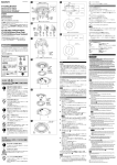
3-861-262-04(1) M 2– .5 Surface where tripod adapter is to be installed この取扱説明書には、事故を防ぐための重要 な注意事項と製品の取り扱いかたを示してい ます。この取扱説明書をよくお読みのうえ、製 品を安全にお使いください。お読みになった あとは、いつでも見られるところに必ず保管 してください。 M3 28 2-F3.5 screw hole 42 44.5 VCT-55I © 1997 by Sony Corporation Printed in Japan English Overview VCT-55I is a tripod adapter which isolates the camera from the equipment. Use either M3 screws or tripod screws to install the adapter to the equipment. Camera modules to be used •XC-55 •Control unit of XC-55BB 2.5 20 27 お買い上げいただきありがとうございます。 3 Operating Instructions 取扱説明書 3.1s4 screw hole 1/4"-20UNC Tripod adapter screw hole F4 M3 hole F3.1 screw hole 6 2– Tripod Adaptor Fig. B Fig. A = 4 – 5 mm Tripod adapter screw 51.5 Material: ABS Cautions on installation •Use phillips M 3×6 screws (supplied) for installation to camera module. •The surface where the adapter is to be installed should be level. •Do not install the tripod adapter in areas where vibration is excessive. Do not use the tripod adapter on vibrating equipment. Size of tripod screws •Screws should not protrude more than 4 to 5 mm () from the surface where adapter is to be installed. (Fig. B) •Insure that the screws do not protrude more than 5.5 mm from the surface. (unit: mm) M3 screw size •Eight millimeter M3 screws are supplied. You may use screws of another size as long as the length is appropriate. Screws should not protrude more than 4 to 5 mm () from the surface where the adapter is to be installed. (Fig. B) •Insure that the screws do not protrude more than 5.5 mm from the surface when installed. Supplied accessories M3 × 6 screws with spring washers (4) (For installation to camera module) M3 × 8 screws with spring washers (2) (For installation to the equipment) Operating Instructions (1) Design and specifications are subject to change without notice. 日本語 図.A M3ネジ基準穴 φ3.1穴 1/4"-20UNC カメラ三脚用ネジ –φ 4 3 44.5 ターが設置物から脱落して、 51.5 けがの原因となることがあり 材質:ABS ます。 VCT-55Iはカメラを装置本体と絶縁で きる三脚アダプターです。 装置への設置は、 M3ネジまたは三脚ネ ジのどちらでも取り付けることができま す。 使用できるカメラモジュール •XC-55 •XC-55BBのコントロール部 設置についてのご注意 •本機をカメラモジュールに取り付ける ときは、付属のネジ (M3×6)を使用し てください。 •本機の取り付け面は、段差のない平面 としてください。 2-φ3.5穴 42 と、カメラおよび三脚アダプ •激しく振動する場所や装置への設置、 使用は行わないでください。 三脚ネジを使用する場合 •本機の取り付け面からの飛び出し量 ()が4〜5mmのネジを使用してく ださい。 (図.B) •飛び出し量が5. 5mmを越えないよう にしてください。 M3ネジを使用する場合 •長さ8mmのネジを付属しています が、設置面の厚さによってはそれ以外 の長さのネジも使用することができま す。その場合は、本機の取り付け面か らの飛び出し量()が4〜5mmのネ ジを使用してください。 (図.B) 三脚ネジ M3 28 指定外のカメラに使用する 概要 三脚アダプター取り付け面 2 –M 2 指定されたカメラ以外に使 用しない 強制 2.5 20 27 け が をしたり周 辺 の 物 品に 損害を与えることがあります。 3.1x4長穴 .5 下 記 の 注 意 を 守らな いと、 図.B 6 (unit: mm) •飛び出し量が5. 5mmを越えないよう にしてください。 付属品 ネジM3×6、スプリングワッシャー付き (4) (カメラモジュール取り付け) ネジM3×8、スプリングワッシャー付き (2) (装置取り付け) 取扱説明書(1) 仕様および外観は、改良のため予告なく 変更することがありますが、 ご了承くだ さい。 = 4 – 5 mm