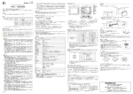
1
Instruction Manual FUJI AC SERVO AMP. FALDIC W Series TYPE RYC Thank you very much for purchasing the Fuji AC Servo System FALDIC-W series. Please read this instruction manual carefully and be familiar with safety precautions before operation. Check if the delivered product is identical to the one you requested. If you find any crack, scratch or other damage on the product, please contact the sales office you purchased. [Relevant information] Manuals for function or specification details, wiring, settings and maintenance are available. Please contact your nearest sales office. Fuji Servo System FALDIC-W Series User's Manual MHT273 Application to "Harmonics control guidelines" All models of the servo amplifier used by specific customers apply to the "Harmonics control guidelines for customers receiving high voltage or special high voltage power" established by the Ministry of Economy, Trade and Industry. Calculate the equivalent capacity or the harmonic current to take appropriate measures. The servo amplifier operated with 3-phase 200V power and 4.0kW or less has been applicable to the "Harmonics control guidelines for home electric appliances and general products" (established in September 1994 and revised in October 1999). It was put out of the guidelines in January 2004. Self-harmonic control is individually implemented. We recommend that the reactor (for control of harmonics) be connected to the servo amplifier to control harmonics as before. Use the reactor specified in the brochure or the user's manual. CAUTION Be sure to deliver this instruction manual to the actual user. Read and be familiar with this instruction manual before installation, connection (wiring), operation and maintenance of the servo amplifier. The product may be changed for improvement without prior notice. INR-SI47-0853c-JE 1. Introduction ■Please confirm the type Check if the delivered product is identical to the one you requested. RYC 201 D [Basic type] RYC:FALDIC-W series [Capacity] 500: 500×100=0.05kW 201: 200×101=0.2kW 202: 200×102=2.0kW [Series] D:3000[r/min] C:2000[r/min] B:1500[r/min] [Development order] 3 - V V T 2 [Input voltage] 2: 3PH AC200[V] [Encoder] T:17-bit INC [Upper interface] V:Di/DO (pulse train , analog voltage) [Major functions] V:Position,Speed,Torque 2. Safety Instructions Read this instruction manual carefully before operation and use the equipment correctly. Be familiar with knowledge, information about safety and other related instructions of the equipment before operation. Safety instructions are classified into the ranks of "Danger" and "Caution." Warning Meaning WARNING If operation is incorrect, a dangerous situation may occur, resulting in death or serious injuries. CAUTION If operation is incorrect, a dangerous situation may occur, resulting in minor to medium injuries or only physical damage to equipment. An item described under Caution may result in a serious accident, depending on the situation. Both items indicate important procedures, and make sure to observe them. After reading this manual, keep it in a place where an operator can access it at any time. WARNING Never touch components inside the servo amplifier and live terminal blocks as you may receive an electric shock. Do not damage cables, subject them to undue stress, put any heavy object on them or pinch them or electric shock may result. Do not touch the rotating part of the motor during operation as you may be injured. Make sure to use the grounding terminal (Class 3 grounding or better) for the servo amplifier or the motor or you may have an electric shock. Be sure to ground it for improvement of noise resistance and reduction of radiant noise. Perform wiring and inspection after waiting 5 minutes after shutting off the power and after confirming that the charge LED is OFF. Use an insulated tool or you may have an electric shock. Do not modify the equipment or you may have an electric shock or be injured. CAUTION Use the specified combination of the servomotor and the servo amplifier or fire or failure may occur. (For details, refer to the user's manual.) Do not use the system in a place where it is exposed to water, a corrosive atmosphere or flammable gas atmosphere, or beside a flammable item as fire or failure may result. Be careful as the temperature of the servo amplifier, servomotor and peripheral devices is high and may cause burns. The temperature of the cooling fin, regenerative resistor, servomotor, etc. may be high during power supply or soon after shutting off the power. Do not touch it or you may be burned. Do not hold the cable or the motor shaft during transportation as failure or injuries may result. Connect wires correctly or the servomotor may be overdriven. Failure or injuries may result. Do not ride on the product or put a heavy object on the product as injuries or damage may result. Never perform megger check or voltage resistance test or failure may result. Do not subject to strong impact or failure may result. Close the intake or exhaust opening of the fan to prevent entry of foreign matter or fire may result. CAUTION Make sure to observe the installation direction described in 3 or fire or failure may result. Never make extreme adjustments because it may cause unstable operation. Injuries may result. During the test operation, fix the servomotor and check operation of the servomotor with it separated from the machine before installing it in the machine or injuries or damage may result. The retention brake is not the stop system for safety of the machine. Provide a stop system to ensure safety on the machine or injuries may result. If an alarm occurs, remove the cause and confirm safety. Reset the alarm or injuries may result. After instantaneous stop and recovery, the system may suddenly restart; do not approach the machine. Design the machine so that human safety is ensured even after restart or injuries may result. Make sure that the power specification is correct or failure may result. Provide external emergency stop circuits so that the operation may be stopped immediately and that power may be shut off or injuries may result. The capacitor of the power line will reduce its capacity due to deterioration. To prevent secondary accident due to failure, we recommend replacement in 5 years or failure may result. Do not store the system in a place where it is exposed to rain or water drops or where there is a hazardous gas or liquid. Store the system in a place where there is no direct sunlight and in the range of temperature (-20°C to 85°C). If storage is to be for a long time, contact us. 3. Installation The servo amplifier consists of electric parts including microprocessors, and has heating units. Do not operate in the following environments. Location at a place where there is oil, steam or corrosive gas or much dust. Location at a place where strong electrostatic or magnetic field exists. Prohibited Accommodation in the same panel together with high voltage equipment (3,000V or more). Sharing the same power supply with the equipment which generates large noise Be sure to observe the following conditions for operation. Or service life may be shortened or failure may result. Compulsory Use the system in the range of: ambient temperature: -10°C to 55°C and ambient humidity: 10% to 90%RH. Pay attention to the following points for installation. Install the servo amplifier vertically on the ground so that letters of "FALDIC" on the front panel may be horizontal. Keep the clearance between the unit and the control cabinet inner surface or other components as shown in the figure Caution below. Or fire or failure may result. Some parts of the servo amplifier may become hot during operation. To ensure cooling effect, keep the distance shown below. ① ③ ③ ② ③ Location Distance (1) Upper surface 50mm or more (2) Lower surface 40mm or more (3) Distance from wall 10mm or more (4) Adjacent distance 5mm or more Remark Remove any objects that may block flow of air. When the system is used at 80% ED or less of the rated load, the distance may be 0 mm for operation. 4. Maintenance and Inspection To prevent failure and to continue reliable operation, perform daily inspection and maintenance. Daily inspection Check visually for faults during operation. Usually check the following items: 1) Check if there is much dust on the servo amplifier. 2) Check if the ambient environment (temperature, power supply, etc.) satisfies the specifications. Charge LED 3) Check if the keypad panel display is correct. 4) Check if there is unusual noise, unusual vibration or foul odor. 5) Check if there is trace of overheat or discoloration. Regular inspection Perform regular inspection after stop of the system and shutoff of the power. Even if the power is shut off, it takes time until the smoothing capacitor in the DC main circuit is completely discharged. Be sure to check if the charge LED is OFF before inspection. Regular inspection list Inspection area Ambient environment Voltage Inspection item Inspection method Check ambient temperature, humidity, vibration Visual check and or atmosphere (presence of dust, gas, oil mist, water drop, etc.). Check if foreign matter like a tool or hazardous object is left unattended. Is the main circuit input voltage correct? measurement with instruments Measurement with a tester Evaluation criteria The specification shall be satisfied. Nothing shall be left unattended. The specification shall be satisfied. Keypad panel Is the display clearly read? Are characters completely displayed? Visual check Display shall be read. There shall be no Connector Are fixing screws loose? Is a connector damaged? Is there loosening or disconnection at the Retightening Visual check There shall be no Retightening Visual check Removal of dust There shall be no fitting? Cooling fan Are bolts loose? Is there any discoloration due to overheating? Is there clogging or adhesion of foreign matter at the cooling fin, intake or exhaust port? fault. fault. fault. with vacuum cleaner ■Parts for replacement Service lives of parts are determined according to their types. They also vary depending on the ambient environment and operating conditions. Use the table below as guidelines for replacement. Contact us for replacement procedures. Part name Cooling fan Smoothing capacitor Other capacitors Other parts Use conditions Standard years for replacement 3 years 5 years 7 years - Replacement method and others Replace with a new part. Replace with a new part. (Replace it after check.) Replace with a new part. (Replace it after check.) To be determined after check. Ambient temperature:30℃ in average year、Load factor:80% or less of ratings、Utilization rates:20 hours or less/a day 5. Warranty 5-1 Free-of-charge Warranty Period and Warranty Details Free-of-charge warranty period The warranty period of the product shall be "1 year after purchase" or "18 months from the manufacturing date described on the nameplate", whichever is earlier. This warranty period may not be applicable if operation environment, operating conditions, operation frequency or number of operations may affect the product service life. The warranty period for repair performed by the Service Dept. is "6 months after completion of repair." Failure diagnosis Primary failure diagnosis should be implemented by the customer. This service may be provided on payment basis by us or the Service Dept. upon request of the customer. This charge should be paid according to our specified prices by our customer. Non-liability for warranty such as loss of opportunity Regardless of the free-of-charge warranty period, warranty for loss of opportunities at the customer or its customer, for damage to non-Fuji Electric's parts, and for other operations shall be excluded. 5-2 Repair Period and Supply Period of Service Parts after Discontinuation of production For a model (product) that discontinued production, we continue to repair the system for 7 years from the date when the production was stopped. We will supply major service parts for repair for 7 years from the date when the production was discontinued. Since life cycles of electronic parts are short, it may be difficult to make procurement or production. Some parts may not be provided within this period. For details, please contact our sales office or service office. 6. Notes for standard 6.1.Installation environment 6.1.1.Ambient climatic conditions Ambient conditions In transportation and storage (*1) Control rooms and equipment rooms (*1)(*2) Installation place Temperature Humidity Air pressure Temperature Humidity Air pressure Vibration / shock Amplifier -20 to +80[℃] 90[%] RH max. 70 to 106 [kPa] -10 to +55[℃] 90[%] RH max. 70 to 106 [kPa] For indoors, 1000 [m] and below of site-altitude, under clean atmosphere, no explosive hazardous gas and vapour is existing. In the case of compliance with the European standard : Pollution degree = 2, Over voltage category = Ⅲ 4.9 [m/s2] / 19.6 [m/s2] acceleration, acceptable (max.) (*1) Free from condensation, no condensation, no formation of ice (*2) Site-altitude should be 1000[m] and below. 6.1.2. Avoid use under the following conditions. (i) Location near oil, steam or corrosive gas (ii) Location where strong electric or magnetic field exists (iii) Accommodation in the same control cabinet together with high voltage (2[kV] or higher) equipment (iv) Sharing of the same power supply with the equipment which generates large noise. (v) In vacuum (vi) In explosive atmosphere (vii) Under acceleration vibration 6.1.3.Internal Motor Overload protection 110% of Motor FLA The overload detecting time (guidepost) is as follows. Output torque [%] Overload detecting time approx. [sec] 100 (rated torque) Continuous operation is acceptable. 125 35 150 18 200 9 300 3 6.2.Mounting 6.2.1 Mounting Amplifier should be mounted upright so that character “FALDIC” on the front panel can be seen horizontal. 6.2.2. Avoid overheating of the amplifier When accommodating multiple amplifiers in the same panel, they should be installed side by side with the sufficient clearance distances below secured. [unit : mm (min.)] (A)Upper and front (B)Lower (C)Left and right 50 40 (E) (A) 10 (D)Between amplifiers (i) 5 (ii)If the clearance is 4.9 [mm] and below, operation duty type of amplifier is reduced to 80%ED (*), instead of continuous duty. (E) Fan mounting (*)80%ED : Cyclic duration factor operating duty is 80% : Intermittent periodic duty. (C) (D) (A) (B) (C) The factor is difined as N (operation under rated conditions) N (operation under rated conditions) + R(at rest and de-energized) ×100 [%] Intermittent periodic duty involve alternating operating and loading times and pauses during which a motor (or amplifier) is at a standstill (or de-energized). The loading and standstill times of one cycle, which has a duration of 10 minutes, are so short that the steady-state temperature cannot be attained. The cycle duration factor is the ratio between the operating or loading time and cycle duration. An ambient temperature of the amplifier must be kept at 55 [℃] maximum, at different points around the amplifier, at a distance of 50[mm] maximum from the amplifier. To keep the above mentioned ambient temperature of amplifier, the amplifier should be mounted in a forced-fan-ventilated panel or equivalent cooling conditions. Avoid the excessive temperature rise due to heat losses by the regenerating braking resistor etc. in the cabinet. 6.2.3.Forced-fan-ventilated panel Provide an exhaust port and an air intake (suction) port in the panel, and mount a fan to the exhaust port to forced ventilate the internal air. Also, mount an air filter to the air intake port in order to maintain an environment better than IEC60664-1 pollution degree 2 (*) in the panel. For the air volume and the opening size of the air intake, refer to the following table. (*)Pollution degree 2: An environment in which only non-conductive pollution is generated, except for occasional occurrence of temporary conductivity due to condensation. ●Input voltage class :200[V] Amplifier output [kW] Air volume of forced-ventilation-fan Opening size of air intake (suction air) 0.05, 0.1 0.2 0.4 0.5, 0.75 0.85, 1.0 [m /min] [m2] 0.06 0.0009 0.11 0.0019 0.23 0.0038 0.43 0.0071 0.57 0.0095 [kW] 1.3,1.5 1.8, 2.0 2.9 [m /min] [m2] 0.85 0.0142 1.14 0.0189 2.84 0.0473 3 Amplifier output Air volume of forced-ventilation-fan Opening size of air intake (suction air) (1) 3 (5) (4) (1) Exhaust air (2) Air intake, suction air (3) Air filter (4) Amplifier (5) Fan (6) Forced-fan-ventilated control cabinet (2) (6) (3) 6.3. Peripherals 6.3.1.Auto circuit breaker For compliance with UL standards, connect UL-approved (with LISTED UL mark) auto circuit breaker between the power supply source and the power filter. Input voltage class [V] 200 Amplifier output [kW] 0.05 to 0.2 0.4 0.5 to 1.3 1.5 1.8 to 2.9 Amplifier type:RYC□□□ 500 to 201 401 501 to 132 152 182 to 292 Auto type BU-ECA 3005 3010 3015 3020 3030 circuit Breaker current [A] 5 10 15 20 30 Manufacturer Fuji Electric FA Components & Systems Co.,Ltd. 6.3.2. Cables Power supply and control circuit cables in the internal of the control panels are as follows : (1) Power supply and motor input cables ■Cable size Input voltage class [V] 200 Amplifier output Amplifier type Conductor sectional area of cable AWG 2 ([mm ]) Power supply, motor (earth) [kW] 0.05 to 1.5 1.8 to 2.0 2.9 RYC□□□ 500 to 152 182 to 202 292 AWG16(1.25) AWG14(2.0) AWG12(3.5) input, ground Brake AWG16(1.25) Power supply for control AWG18(0.75) Tightening torque [in/b]([N・m]) - 11.0 (1.22) ■Cable type Use copper wires of allowable maximum temperature 75℃ Recommended cable (i) 600V class, poly-vinyl insulated cable (JIS C 3307) or (ii) Poly-vinyl insulated cable “KIV” (JIS C 3316) or (iii) 600V class, cross-link polyethylene insulated cable “FSCL” (JCS 360)or equivalent In case of use in Europe, please select Cable according to EN60204-1,AnnexC.4 (2) Control input/output cables for CN1 : + 24 [V], 50 [mA] max. ■Cable size 18-core twisted-pair shielded cable. AWG No.26 ■Cable type “XEBV” or “XEWV” (The Furukawa Electric Co. , Ltd.) or equivalent (3) Encoder cables for CN2 (4Mbps serial communication) Cross-link polyethylene insulated, poly-vinyl sheath cables RMCV-SV type : Wiring length with in Cable size and pair, core quantities 20 [m] or less AWG No.24 / 3-pair (max) 6.4.Compliance with EC directives(TUV,CE) 6.4.1. General The general-purpose servo amplifier becomes the object of Low Voltage Directive in Europe. The FALDIC-W series acquires the recognition of the effect that has suited EN50178/1997 by the inspecting agency in Europe. Agreement to Low Voltage Directive is independent declared. 6.4.2. Attention ・Ground terminal E(earth) for the servo amplifier earth surely. Do not do the electric shock protection with leak breaker (RCD) alone. ・The earth cable must use the size of the electric wire of the current capacity more than the equal to the input electric wire. ・Breaker (MCCB) and electromagnetic contactor (MC) for wiring must use the one in accordance with EN or the IEC standard. ・Use leak breaker (RCD) that can detect direct current on the power supply side of the servo amplifier when leak breaker (RCD) is used as protection of contact or direct indirect contact. When it is not so, the protection to which the servo amplifier and peripherals are separated by the double insulation or the reinforced insulation or the servo amplifier with the transformer and insulation with the main power supply method is needed. ・Please set up the servo amplifier in the environment of pollution level 2. Please set it up IP54 or in a board any more when you set up the servo amplifier in the environment of pollution level 3 or 4. ・When the person can easily touch the terminal and Den for the earth of the servo amplifier, it is installation in the case or the barrier of IP4X as for the servo amplifier. Moreover, do treatment similar as for exchange reactor (ACR) for the moment of force improvement, direct current reactor (DCR) for the moment of force improvement, and the output filter. ・This product should be installed in the electrical cabinet. ・Servo driver is used under the "pollution degree 2" environment as specified in IEC60664-1. 6.4.3.Peripheral equipment (2) (3) (4) (5) (2) (1) (5) (6) (7) (9) (3) (6) (8) (4) (1)Power Supply Source : Neutral Earthed 3 Phase Power Supply System (7) (8) (9) Amplifier Motor Control panel Reinforced isolation transformer Earth leakage circuit breaker Auto circuit breaker Power filter 24[V] DC power source (a) Power filter Regarding the EMI terminal disturbance voltage, a power filter is required. [Recommended filter] Input voltage class [V] 200 Amplifier output [kW] 0.05 to 0.4 0.5 to 1.0 1.3 to 1.8 2.0 to 2.9 ① 3SUP-HL05-ER-6 3SUP-HL10-ER-6 3SUP-HL20-ER-6 3SUP-HL30-ER-6 ② HF3005A-TM HF3010A-TM HF3020A-TM HF3030A-TM Manufacturer ① OKAYA ELECTRIC INDUSTRIES CO.,LTD. ② SOSHIN ELECTRIC CO.,LTD. (b) Earthing (grounding) To prevent electric shocks, the amplifier protection earth terminal and the control panel protection earth terminal shall be connected to the earthed-neutral terminal of the power system described in the item (1) above. When connecting earth cables to the protection earth terminal, do not tighten the cable terminals together. The amplifier has two protection earth terminals. Do not connect copper cables directly to the amplifier terminals. For the earth connection avoid direct contact between aluminum and copper.Tin-plated cable lugs can be used if the plating does not contain zinc. When tightening the screws take care not to damage the thread in the aluminum frame. (c) Auto circuit breaker Connect EN/IEC-approved auto circuit breaker between the power supply source and the power filter. (d) Residual-current-operated protective device (RCD) Where residual-current-operated protective device (RCD) is used for protection in case of direct or indirect contact, only RCD of type B is allowed on the supply side of this electric equipment (EE). Otherwise another protective measure should be applied such as separation of the EE from the environment by double or reinforced insulation or isolation of EE and supply system by a transformer. (e) Conformity to EMC requirements When the amplifier and motor have been finally installed with a driven machine and devices, they may not conform to the EMC requirements because the installation, wiring, etc. are different according to the final conditions. The driven machine and devices must therefore be measured for conformity to the EMC requirements under the final conditions with the amplifier and motor installed. Power filter type 6.5.Compliance with UL standards 6.5.1.General The UL standard is a safety standard by which a fire of the United States and other accidents are prevented by the abbreviation of the Underwriters Laboratories Inc., and user, serviceman, and general people protect it. The cUL standard is a standard enacted for UL to suit the CSA standard. The cUL standard recognition goods have the effect equal with the CSA standard recognition goods. 6.5.2. Attention • [WARNING] RISK OF ELECTRIC SHOCK Don't touch the controller while applying power and at least 5min , after disconnecting power . • [WARNING] Take care of electric shock. Be sure to turn the AC servo amp off before starting work. • [CAUTION] When the charge lamp is lit, the AC servo amp is still charged at a dangerous voltage. • [WARNING] There are two or more live parts inside the AC servo amp. • [WARNING] Securely ground (earth) the controller . • [CAUTION] Hot controller (My cause burn ) Don't touch the controller while applying power . • The AC servo amp is approved as a part used inside a panel. Install it inside a panel. • Suitable for use on a circuit capable of delivering not more than 5,000 rms symmetrical amperes, 240 Volts Maximum.Connect the power supply satisfying the characteristics shown in the table below as an input power supply of the AC servo amp (short circuit rating) Input voltage class AC240V Input current 5,000A or less • Perform wiring to the input, output and control terminals of the AC servo amp. Use UL certified round crimp terminal to the input and output terminals with insulation cover or covered with reduced tube to obtain the insulation distance. Use a cramping tool recommended by the terminal manufacturer when fabricating crimp terminals. -URL: http://www.fesys.co.jp/eng/ -Phone : +81-3-5435-7283 -FAX : +81-3-5435-7425 -Company Adress: Gate City Ohsaki, East Tower 11-2, Osaki 1-chome, Shinagawa-ku, Tokyo, 141-0032, Japan Established on 08.2006 取扱説明書 富士 AC サーボアンプ FALDIC W シリーズ 型式 RYC このたびは、富士ACサーボシステム FALDIC-W シリ-ズをお買いあげいただきましてまことにありがとう ございます。取り扱いにつきましては、この取扱説明書をよくお読みになり、安全に関する内容をご理解いた だいたうえでご使用されることをお願いいたします。お届けされた商品がご要求のものかどうか確認ください。 また、万一商品にワレ、キズ、その他欠損がございましたら、お買い求めの営業所までご連絡ください。 [関連資料] 機能や仕様の詳細、配線、設定、メンテナンスのためのマニュアルを準備しておりますので、最寄りの営業所 へご連絡ください。 富士サーボシステム FALDIC W シリーズユーザーズマニュアル MHT273 「高調波抑制対策ガイドライン」への適用について 特定需要家において使用されるサーボアンプは、全ての機種が経済産業省制定の「高圧又は特別高圧で受電 する需要家の高調波抑制対策ガイドライン」の対象です。等価容量計算や高調波流出電流の計算を行い、適切 な対策の実施をお願いします。 また、3相200V電源で4.0kW以下のサーボアンプは、経済産業省より出されていた「家電・汎用品 高調波抑制対策ガイドライン」(1994年9月制定,1999年10月改正)の対象製品となっておりました が、2004年1月より対象から外れることとなり、個々に自主的な高調波抑制対策を行うこととなりました。 当社では、高調波抑制対策として従来どおりサーボアンプに(高調波抑制用)リアクトルを接続することを 推奨いたします。このリアクトルはカタログやユーザーズマニュアルに記載のものをご使用ください。 注意 ■この取扱説明書は、実際にご使用になる方に確実に届くようご配慮ください。 ■この取扱説明書を読み、理解したうえで、サーボアンプを据付、接続(配線)、運転、保守点検をしてください。 ■製品は改良のため予告なしに変更されることがあります。 INR-SI47-0853c-JE 1.はじめに ■型式をご確認ください 開梱されましたらご注文通りのものであるかご確認ください。 RYC 201 D 3 - V V T 2 【基本形式】 RYC:FALDIC-Wシリーズ 【容量表示】 500:500X100=0.05kW 201:200X101=0.2kW 202:200X102=2.0kW 【シリーズ名】 D:3000[r/min] C:2000[r/min] B:1500[r/min] 【電圧】 2:三相200[V] 【エンコーダ】 T:17ビット INC 【上位I/F】 V:汎用インターフェイス (パルス列・アナログ電圧) 【主機能】 V:位置/速度/トルク制御 【開発順位】 2.安全上の注意事項 ご使用の前に、この取扱説明書を読み、正しくお使いください。 機器の知識、安全情報、及び注意事項の全てを習熟してからお使いください。 ここでは、安全注意事項のランクを「危険」,「注意」として区分してあります。 警告表示 意 味 警告 取り扱いを誤った場合に、危険な状況が起こりえて、死亡又は、重傷を受ける可能性 が想定される場合。 注意 取り扱いを誤った場合に、危険な状況が起こりえて、中程度の傷害や軽傷を受ける場 合及び物的損害だけの発生が想定される場合 なお、注意に記載した事項でも、状況によっては重大な結果に結びつく可能性があります。 いずれも、重要な内容を記載していますので必ずお守りください。 お読みになった後は、使用者がいつでも見られる場所に保管してください。 警告 ●サ-ボアンプの内部および通電中の端子台には、絶対に触らないでください。感電の恐れがあります。 ●ケ-ブルは傷をつけたり、無理なストレスをかけたり、重い物を載せたり、挟み込んだりしないでください。 感電の恐れがあります。 ●運転中、モ-タの回転部には絶対に触れないようにしてください。けがの恐れがあります。 ●サ-ボアンプおよびモ-タは必ずアース端子 を使用してアース接地(第3種接地以上)してください。 感電の恐れがあります。ノイズ耐量の向上、放射ノイズの減少を図るためにも必ず接地してください。 ●配線・点検は、電源を OFF してから5分以上が経過し、チャ-ジ LED の消灯を確認してから実施ください。 ●絶縁工具を使用してください。感電の恐れがあります。 ●改造は絶対に行わないでください。感電・けがの恐れがあります。 注意 ●モ-タとサ-ボアンプは、指定された組合せでご使用ください。火災・故障の原因となります。 (詳細は、ユ-ザ-ズマニュアルを参照ください) ●水のかかる場所や、腐食性の雰囲気、引火性ガスの雰囲気、可燃物のそばでは絶対に使用しないでください。 火災、故障の原因となります。 ●サ-ボアンプ・モ-タおよび周辺機器は、温度が高くなりますのでご注意ください。やけどの恐れがあります。 ●通電中や電源遮断後しばらくの間、冷却フィン、回生抵抗、モ-タ等は高温になる場合がありますので、触れ ないでください。やけどの恐れがあります。 ●運搬時には、ケ-ブルやモ-タ軸を持たないでください。故障、けがの恐れがあります。 ●配線は確実に行ってください。モ-タ暴走の原因になります。けが、故障の恐れがあります。 ●製品の上に乗ったり、重い物を載せないでください。けが、破壊の恐れがあります。 ●メガチェックや耐圧試験は絶対に行わないでください。故障の原因になります。 ●強い衝撃を与えないでください。故障の原因になります。 ●ファンの吸気口、排気口をふさいだり、異物が入らないようにしてください。火災の恐れがあります。 注意 ●取り付け方向は、3項に示す通りに必ずお守りください。火災、故障の恐れがあります。 ●極端な調整変更は動作が不安定になりますので、決して行わないでください。けがの恐れがあります。 ●試運転はモ-タを固定し、機械系と切り離した状態で動作を確認してから機械に取り付けてください。 けが、破壊の恐れがあります。 ●保持ブレ-キは、機械の安全を確保するための停止装置ではありません。安全を確保するための停止装置を機 械側に設置してください。けがの恐れがあります。 ●アラ-ム発生時は、原因を取り除き、安全を確保してからアラ-ムリセットをしてください。 けがの恐れがあります。 ●瞬停復電後、突然再始動する可能性がありますので、機械に近寄らないでください。 ●再始動しても人に対する安全性を確保するよう機械設計を行ってください。けがの恐れがあります。 ●電源仕様が正常であることを確認ください。故障の原因になります。 ●即時に運転を停止し、電源を遮断できる様に、外部に非常停止回路を設けてください。けがの恐れがあります。 ●電源ラインのコンデンサは、劣化により容量低下します。故障による二次災害を防止するため、5年程度で交 換されることを推奨します。故障の原因になります。 ●雨や水滴のかかる場所、有毒なガスや液体のある場所では保管しないでください。 ●直射日光のあたらない場所で、温度範囲(-20℃~85℃)の雰囲気内で保管してください。 ●保管が長期にわたった場合は、当社にお問い合わせください。 3.設置 サ-ボアンプは、マイクロプロセッサを使用した電気部品で構成され、また発熱部を持っていますので、次の禁 止内容をお守りください。 ●周囲に油、水蒸気、腐食性ガスのある場所および、塵埃の多い場所での使用。 ●強電界、強磁界のある場所での使用。 ●高圧機器(3,000V 以上)と同一盤内での使用。 ●高ノイズを発生する機器と同一電源での使用。 禁止 次の条件を守ってご使用ください。寿命を短くしたり、故障の原因になります。 強制 ●周囲温度:-10℃~55℃,周囲湿度:10%~90%RH の範囲でご使用ください。 取り付け時には、次の点にご注意ください。 本体正面パネル「FALDIC」の文字が水平に見えるよう地面に対してサーボアンプを 垂直に取り付けてください。 本体と制御盤内面または、その他の機器との間隔は、下図のように 距離を確保してください。火災、故障の恐れがあります。 注意 サ-ボアンプは、運転に伴い発熱する部分があります。 冷却効果を確保するために、下図に示す空間を設けてください。 ① ③ ③ ② ③ 箇所 距離 ①上面 50mm 以上 ②下面 40mm 以上 ③壁と の距離 10mm 以上 ④隣接 間距離 5mm 以上 備考 空気の流れをさまたげないよう障害物は 取り除いてください。 定格負荷の 80%ED 以下でのご使用の場 合は、0mm でもご使用いただけます。 4.保守・点検 故障を未然に防いで信頼性の高い運転を継続するために、日常点検や定期点検を行ってください。 ■日常点検 運転中に目視で異常の有無を確認します。通常、次の点検を行います。 1)サーボアンプに多量のほこりがたまっていないか? 2)周囲環境(温度、電源等)は、仕様を満足しているか? チャージ 3)タッチパネルの表示に異常はないか? LED 4)異常音、異常振動、異臭はないか? 5)過熱の跡や変色などの異常はないか? ■定期点検 定期点検は運転停止後、電源を遮断してから行ってください。電源を OFF しても主回路直流部の平滑コンデンサ が放電するには時間がかかります。必ずチャ-ジ LED の消灯を確認してから点検するようにしてください。 定期点検リスト 点検箇所 周囲環境 電圧 タッチパネル コネクタ 冷却ファン 点検項目 ●周囲温度、湿度、振動、雰囲気(塵埃、ガス、オ イルミスト、水滴などの有無)の確認 ●周囲に工具などの異物や危険物が放置されていな いか? ●主回路入力電圧は正常か? ●表示が見えにくくないか? ●文字などが欠けていないか? ●固定ネジのゆるみはないか? ●破損はしていないか? ●圧着部にゆるみや断線はないか? ●ボルト類にゆるみはないか? ●過熱による変色はないか? ●冷却フィンや吸気、排気口の目詰まり、異物の付 着はないか? 点検方法 ●目視および計器にて 測定 ●目視 判定基準 ●仕様を満足すること ●放置なきこと ●テスタ-などで測定 ●目視 ●仕様を満足すること ●表示が読めて、 異常なきこと ●異常なきこと ●増し締め ●目視 ●増し締め ●目視 ●掃除機等で粉塵除去 ●異常なきこと ■交換部品 部品は、その種類によって決まる寿命があります。部品の寿命は、周囲の環境や使用条件によって異なりますが、 下表を交換の目安としてください。交換作業につきましては弊社まで相談ください。 部品名 標準交換年数 冷却ファン 平滑コンデンサ 3年 5年 新品と交換 その他のコンデンサ 7年 新品と交換(調査の上交換) その他の部品 - 使用条件 交換方法・その他 調査の上、決定 周囲温度:年平均 30℃、負荷率:定格の 80%以下、稼働率:20 時間以下/日 5.保証 5-1.無償保証期間と保証内容 ■無償保証期間 商品の保証期間は「お買い上げ後 1 年」もしくは「銘板に記載されている製造年月より 18 ヶ月のいずれか早く 経過するまでの期間となります。 但し、使用環境、使用条件、使用頻度や回数などにより、商品の寿命に 影響を及ぼす場合は、この保障期間が適 用されない場合があります。 なお、弊社サービス部門が修復した部分の保証期間は、 「修復完了後 6 ヶ月」となります。 ■故障診断 一次故障診断は、原則としてお客様にて実施をお願いします。但し、お客様の要請により弊社または弊社サービ ス網がこの業務を有償 にて代行することができます。この場合の有償料金は弊社の料金規定により、お客様にて ご負担をお願い致します。 ■機会損失などの保証責任の除外 無償保証期間内外を問わず、弊社商品の故障に起因するお客様あるいは お客様の顧客側での機会損失ならびに弊 社商品外への損傷、その他業務に対する保証は弊社の保証外とさせて頂きます。 5-2.生産中止後の修理期間、補用部品の供給期間 生産中止した機種(商品)につきましては、生産を中止した年月より起算して7年間の範囲で修理を実施致しま す。また、修理用の主要な補用部品についても、生産を中止した年月より起算して7年間の範囲で供給致します。 但し、電子部品等はライフサイクルが短く、調達や生産が困難になる場合も予測され、期間内でも修理や補用部 品の供給が困難となる場合があります。 詳細は、弊社営業窓口またはサービス窓口へ御確認願います。 6.海外規格対応について 6-1.使用環境 6-1-1.周囲の雰囲気 周囲条件 輸送・保存環境 設置環境 サーボアンプ 温度 湿度 気圧 温度 湿度 気圧 設置場所 振動/衝撃 -20 to +80[℃] 90[%] RH max. 70 to 106 [kPa] -10 to +55[℃] 90[%] RH max. 結露無きこと 70 to 106 [kPa] 標高 1000 [m] 以下の室内、塵埃なき清涼な空気のこと 腐食性、爆発性のガス、蒸気等無きこと 欧州規格に適合させる場合 Pollution degree = 2, Over voltage category = Ⅲ 4.9 [m/s2] / 19.6 [m/s2] 6-1-2.使用禁止場所 (i) 油、蒸気または腐食性ガスの近く (ii) 強い電磁波が存在する場所 (iii) 高電圧(2kV)設備を伴う同じ制御盤での使用 (iv) 大きい雑音を発生させる設備と同じ電源にて使用 (v) 真空 (vi) 爆発性大気の中 (vii) 加速振動の下 6-1-3.過負荷保護 過負荷検出時間の目安は以下の通りです。 出力トルク [%] 過負荷検出時間約 [sec] 100 (定格トルク) 連続運転可能 125 35 150 18 200 9 300 3 6-2.設置 6-2-1.取付け方向 サーボアンプは、フロントパネルの文字"FALDIC"が水平になるよう サーボアンプの長手方向が垂直になるように取り付けてください。 (E) 6-2-2.サーボアンプ過熱防止 (A) 同じ制御盤に複数のアンプを収容する場合、各アンプ間や周囲との距離 は下表の距離を確保してください。 [単位 : mm (min.)] (A)上面および前面 (B)下面 (C)右および左 50 40 10 (D)サーボアンプ間 (i) 5 (ii) 5[mm]未満の場合、サーボアンプの連続運転定格は80%ED に低減さ れます。 (E) ファンを設置のこと (C) (D) (A) (B) (C) 負荷率は、次の式で定義されます。 N(定格負荷での運転時間) ×100 [%] N (定格負荷での運転時間) + R(停止・無負荷時間) 1周期 負荷 損失 →時間 10 分間程度の短い間しか継続しない周期運転では、温度は上昇しません。 継続的な周期運転とは、モータの運転と停止動作が交互に長時間行われることを言います。 負荷率とは、その周期内での運転時間の占める割合のことを言います。 サーボアンプの周囲温度は、サーボアンプから 50[mm]離れた位置で 55℃以下であること。 周囲温度をサーボアンプの仕様内に保つために、 サーボアンプは通気された強制換気された制御盤か同 等の冷却状態の場所に取り付けてください。制御盤内の制動用抵抗等の発熱による、過度の温度上昇を 避けて下さい。 6-2-3.強制換気 排気口に強制換気用ファンを設けて下さい。IEC60664-1 汚染度 2(*)より良い環境を維持するためにエアフィルタを空気吸 気口に取り付けてください。 空気取り入れ口の開口面積は、下表を参照してください。 (*) 汚染度 2: 非導電性汚染だけが発生する環境。 (結露による一時発生的な導電を除く) ■入力電圧クラス:200[V] サーボアンプ出力 [kW] 強制換気風量 吸気口の面積 0.05, 0.1 0.2 0.4 0.5, 0.75 0.85,1.0 [m3/min] [m2] 0.06 0.0009 0.11 0.0019 0.23 0.0038 0.43 0.0071 0.57 0.0095 [kW] 1.3,1.5 1.8 , 2.0 2.9 0.85 1.14 0.0189 2.84 0.0473 サーボアンプ出力 3 強制換気風量 [m /min] 2 吸気口の面積 (1) [m ] 0.0142 (5) (1) 排気 (2) (3) (4) (5) (6) (4) 空気取り入れ口、吸気 エアフィルタ サーボアンプ ファン 強制換気にて通気される制御盤 (2) (6) (3) 6-3.周辺機器 6-3-1.オートブレーカ 電源とパワーフィルタ(パワーフィルタを使用しない場合はサーボアンプ)の間に、UL によって承認された(LISTED UL マ ークがある)ブレーカを接続してください。 入力電圧クラス [V] サーボアンプ出力 [kW] サーボアンプ型式:RYC□□□ ブレーカ 型式 BU-ECA 動作電流 製造元 [A] 200 0.05 to 0.2 0.4 0.5 to 1.3 500 to 201 401 501 to 132 152 1.8 to 2.9 182 to 292 3020 20 3030 30 3005 3010 3015 5 10 15 富士電機機器制御株式会社 1.5 6-3-2.ケーブル 制御盤内の主電源と制御電源配線に使用するケーブルは下記のものをご使用ください。 (1) 電源とモータ動力ケーブル ■電線サイズ 入力電源クラス [V] 200 [kW] 0.05 to 1.5 1.8 to 2.0 2.9 サーボアンプ型式 RYC□□□ ケーブルの 主電源、モータ動力線、アース線 導体断面積 ブレーキ AWG ([mm2]) 制御電源 500 to 152 182 to 202 292 AWG14(2.0) AWG12(3.5) サーボアンプ出力容量 締め付けトルク([N・m]) AWG16(1.25) AWG16(1.25) AWG18(0.75) - 11.0 (1.22) (max) ■電線型式 最高 75℃を許容できる銅線を使用してください。推奨ケーブルは次の通りです。 (i)ポリビニール絶縁ケーブル(JIS C3307)、600V クラス絶縁 (ii) ポリビニール絶縁ケーブル"KIV"(JIS C3316) (iii) 600V クラス,架橋ポリエチレン絶縁ケーブル “FSCL” (JCS 360)または同等品 欧州でご使用になる場合は、EN60204-1、AnnexC.4 に従ってケーブルを選定してください。 (2) シーケンス入出力用電線(CN1): DC+ 24 [V], 50 [mA] max. ■電線サイズ 18 対ツイストペアシールド線 AWG No.26 ■電線型式 “XEBV” or “XEWV” (古河電工株式会社) または相当品 (3) エンコーダ信号用電線(CN2):DC+5[V]シリアル通信 ■電線サイズ 配線長 電線サイズ 20 [m] 以下 ■電線型式 AWG No.24 / 3-pair 架橋ポリエチレン絶縁ビニルシースケーブルRMCV-SV 6-4.EC指令への適合(TuV、CEマーキング) 6-4-1.概要 汎用サーボアンプは欧州では低電圧指令の対象になります。 FALDIC-Wシリーズは欧州の認定機関によりEN50178/1997に合致していることを取得しています。 また、低電圧指令の適合を自己宣言しています。 6-4-2.注意 ・サーボアンプのアース端子Eは確実に接地してください。漏電ブレーカ(RCD)単独での感電保護をしないでください。 ・アース線は、入力電線と同等以上の電流容量の電線サイズを使用してください。 ・配線用遮断機(MCCB)、電磁接触器(MC)は、EN もしくは IEC 規格に準拠したものをお使いください。 ・漏電ブレーカ(RCD)が、直接接触または間接接触に対しての保護として使われる場合には、サーボアンプの電源側に直流 電流検出可能な漏電ブレーカ(RCD)をお使い下さい。そうでない場合は、二重絶縁もしくは強化絶縁かトランスによるサ ーボアンプと主電源との絶縁によってサーボアンプと周辺機器とを分離するような保護方法が必要となります。 ・サーボアンプは汚染度2の環境に設置して下さい。もし、サーボアンプを汚染度3もしくは4の環境に設置する場合は、IP54 もしくはそれ以上の盤内に設置して下さい。 ・サーボアンプの接地用端子や活電部に容易に人が触れる事が出来る場合には、IP4Xの筐体または障壁内にサーボアンプを取付 けて下さい。 ・サーボアンプの接地用端子や活電部に容易に人が触れる事が出来無い場合には、IP2Xの筐体または障壁内にサーボアンプを取 付けて下さい。 ・また、人体が直接触れない様にする為、力率改善用交流リアクトル(ACR)、力率改善用直流リアクトル(DCR)、出力フィ ルタも上記筐体または障壁内に取付けて下さい。 ・サーボアンプは「IEC60664-1」で指定される「汚染度 2」の環境下で使用して下さい。 6-4-3.周辺機器 (2) (1) (5) (6) (7) (9) (3) (8) (4) (1)電源: 中性点接地 三相交流電源 (2) サーボアンプ (3) サーボモータ (4) 制御盤 (5) トランス (6) 漏電ブレーカ (7) オートブレーカ (8) パワーフィルタ (9) 24V の DC 電源 (a) パワーフィルタ 雑音端子電圧の抑制のためパワーフィルタが必要です。 [推奨フィルタ] 入力電圧クラス [V] サーボアンプ出力 パワーフィルタ型式 製造元 200 [kW] 0.05 ~ 0.4 0.5 ~1.0 ① 3SUP-HL05-ER-6 3SUP-HL10-ER-6 ② HF3005A-TM HF3010A-TM ① 岡谷電機産業株式会社 1.3 ~1.5 2.0 ~2.9 3SUP-HL30-ER-6 3SUP-HL30-ER-6 HF3030A-TM HF3030A-TM ② 双信電機株式会社 (b) 接地 感電を防止するため, サーボアンプの保護アースと制御盤の保護アースは電源側(前記構成図の(1))の中性点に接続してく ださい。 保護アース端子にアース線を接続する際は2本以上の線を供締めしないでください。サーボアンプには保護アース端子を2 つ用意しています。 銅線を直接アンプ端子に接続しないでください。 接地配線の際、アルミニウムと銅を直接接続することは避けてください。 亜鉛を含まないすずめっきのケーブルプラグを使用してください。 ねじ締めの際はケーブルに傷がつかないように注意してください。 (c) オートブレーカ 電源側とパワーフィルタの間に、EN/IEC に認定されたブレーカを接続してください。 (d) 漏電ブレーカ(RCD) 漏電遮断機(RCD)を直接接触または間接接触の漏電保護に使用されるのであれば、このサーボシステムにはタイプ B の漏 電遮断機(RCD)を使用してください。そうでない場合は、二重絶縁もしくは強化絶縁かトランスによるサーボアンプと主 電源との絶縁によってサーボアンプと周辺機器とを分離するような保護方法が必要となります。 (e) EMC 指令への適合 サーボアンプとモーターが機械や機器に組み込まれた場合、配線などの相違でEMC指令に適合しない可能性があります。 したがって機械や機器の最終完成状態でEMC指令に合致しているかを測定する必要があります。 6-5.UL規格への適合 6-5-1.概要 UL規格は、Underwriters Laboratories Inc.の略で、米国の火災、およびその他の事故を防ぎ、使用者・サービスマン・一般 の人々を保護する安全規格です。 cUL規格はULがCSA規格に合うように制定した規格です。 cUL規格の認定商品には、CSA 規格の認定と対等の効果があります。 6-5-2.注意 • • • • • • • • [危険] 感電の恐れあり。通電中および電源遮断後5分間はサーボアンプに触らないでください。 [注意] 感電に注意して下さい。サーボアンプの電源は作業前に必ずオフにして下さい。 [注意] チャージランプが点灯している時は、サーボアンプ内部に危険な電圧が残っています。 [危険] サーボアンプ内には、一ヶ所以上の活電部があります。 [危険] サーボアンプを確実に接地してください。 [注意] 高温注意(火傷のおそれあり) 通電中は本体に触れないで下さい。 盤内使用の製品として認定を取得しています。サーボアンプは盤内に収納して下さい。 サーボアンプの入力電源には、下表に適合する電源を接続して下さい。 入力電圧クラス(最大電圧) AC240V 入力電源電流 5,000A 以下 •サーボアンプの入出力端子は確実に結線して下さい。 UL認定された丸形圧着端子を使用してください。絶縁距離が確保されるよう絶縁カバーや収縮チューブを併せてご使用くだ さい。圧着丸端子メーカ推奨の圧着工具をご使用ください。 ドライブ事業部 〒108-0075 東京都港区港南2丁目4番13号(スターゼン品川ビル) URL http://www.fesys.co.jp/ 発行 富士電機システムズ株式会社 鈴鹿工場 TEL:0120-128-220 〒513-8633 三重県鈴鹿市南玉垣町 5520 番地 FAX:0120-128-230 制定 2006.08