1
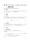
取扱説明書
Instruction Manual
3283
クランプオンリークハイテスタ
CLAMP ON
LEAK HiTESTER
2013年 3月 発行 改訂18版
March 2013 Revised edition 18 3283A980-18 13-03H
目次 1
――――――――――――――――――――――――――
目次
はじめに
点検
安全について
ご使用にあたっての注意
各章の内容
第 1 章 製品概要
1.1 製品の概要
1.2 本器の特長
1.3 各部の名称と機能
第 2 章 測定方法
2.1 測定準備
2.2 漏れ電流の測定 A∼
2.3 フィルタ機能 FILTER
2.4 データホールド機能 HOLD
2.5 レコード機能 REC
2.6 オートパワーオフ機能 APS
2.7 電池消耗警告
2.8 ブザー音
2.9 ファストモード
2.10 出力機能 OUTPUT
第 3 章 電池の交換方法
第 4 章 ハンドストラップの付け方
第 5 章 仕様
5.1 測定仕様
5.1.1 交流電流 Arms(真の実効値表示)
5.1.2 周波数 Hz
5.2 一般仕様
第 6 章 故障とお考えになる前に
第 7 章 アフターサービス
1
1
2
5
9
11
11
12
13
17
17
18
24
25
25
29
29
29
30
31
35
37
39
39
39
40
41
45
47
―――――――――――――――――――――――
目次 2
――――――――――――――――――――――――――
―――――――――――――――――――――――
1
__________________________________________________
はじめに
このたびは、HIOKI“3283 クランプオンリークハイテ
スタ”をご選定いただき、誠にありがとうございます。
この製品を十分にご活用いただき、末長くご使用いた
だくためにも、取扱説明書はていねいに扱い、いつも
お手元に置いてご使用ください。
お願い
本書の内容は、万全を期して作成しましたが、万一ご
不明な点や誤り、記載漏れなど、お気づきの点があり
ましたら、お買上店(代理店)か最寄りの営業所にご
連絡ください。
点検
本器がお手元に届きましたら、輸送中において異常ま
たは破損がないか点検してからご使用ください。特に
付属品および、パネル面のスイッチ、キー、端子類に
注意してください。万一、破損あるいは仕様どおり動
作しない場合は、お買上店(代理店)か最寄りの営業
所にご連絡ください。
付属品
9399 携帯用ケース
ハンドストラップ
電池 6F22 (006P)
取扱説明書
1
1
1
1
オプション
9094 出力コード
9445-02 AC アダプタ
1
1
_____________________________________________
2
__________________________________________________
安全について
危
険
この機器は IEC 61010 安全規格に従って、設計され、試
験し、安全な状態で出荷されています。測定方法を間違え
ると人身事故や機器の故障につながる可能性があります。
取扱説明書を熟読し、十分に内容を理解してから操作して
ください。万一事故があっても、弊社製品が原因である場
合以外は責任を負いかねます。
この取扱説明書には本器を安全に操作し、安全な状態
に保つのに要する情報や注意事項が記載されています。
本器を使用する前に下記の安全に関する事項をよくお
読みください。
安全記号
・使用者は、機器上に表示されている マークの
ところについて、取扱説明書の マークの該当
箇所を参照し、機器の操作をしてください。
・使用者は、取扱説明書の中の マークのあると
ころは、必ず説明を読み注意する必要があるこ
とを示します。
交流(AC)を表示します。
直流(DC)を表示します。
絶縁保護具(電気用ゴム手袋、電気用ゴム長靴、安
全帽など)を着用して、活線状態の電路に着脱でき
ることを示します。
_____________________________________________
3
__________________________________________________
取扱説明書の注意事項には、重要度に応じて以下の
表記がされています。
危険
操作や取り扱いを誤ると、使用者が死亡または重傷に
つながる危険性が極めて高いことを意味します。
警告
操作や取り扱いを誤ると、使用者が死亡または重傷に
つながる可能性があることを意味します。
注意
操作や取り扱いを誤ると、使用者が傷害を負う場合、
または機器を損傷する可能性があることを意味します。
注記
製品性能および操作上でのアドバイス的なことを
意味します。
_____________________________________________
4
__________________________________________________
測定カテゴリについて
本器は CATIII に適合しています。
測定器を安全に使用するため、IEC61010 では測定カ
テゴリとして、使用する場所により安全レベルの基準
を CATⅡ∼CATⅣで分類しています。
CAT II
コンセントに接続する電源コード付き機器(可搬
形工具・家庭用電気製品など)の一次側電路
コンセント差込口を直接測定する場合は CAT Ⅱで
す。
CAT III 直接分電盤から電気を取り込む機器(固定設備)
の一次側および分電盤からコンセントまでの電路
CAT IV 建造物への引込み電路、引込み口から電力量メー
タおよび一次側電流保護装置(分電盤)までの電
路
カテゴリの数値の小さいクラスの測定器で、数値の大
きいクラスに該当する場所を測定すると重大な事故に
つながる恐れがありますので、絶対に避けてください。
カテゴリのない測定器で、CAT Ⅱ∼ CAT Ⅳの測定カ
テゴリを測定すると重大な事故につながる恐れがあり
ますので、絶対に避けてください。
_____________________________________________
5
__________________________________________________
ご使用にあたっての注意
本器を安全にご使用いただくために、また機能を十二
分にご活用いただくために、下記の注意事項をお守り
ください。
危
険
・使用前には、保存や輸送による故障がないか、点検と動作確
認をしてから使用してください。故障を確認した場合は、お
買上店(代理店)か最寄りの営業所にご連絡ください。
・クランプセンサの先端を開いた時、および測定中の短絡、人
身事故などを避けるために、被測定導体が安全電圧を超え
300 V までの測定をする場合は、過電圧カテゴリⅢ、汚染度
2、動作電圧 300 V の基礎絶縁を満足する絶縁導体を使用し
てください。
なお、下線部の用語は下記の規格を参照してください。
IEC 61010-1 (JIS C 1010-1)
IEC 61010-2-031 (JIS C 1010-2-031)
IEC 61010-2-032 (JIS C 1010-2-032)
・クランプセンサの先端を開いたときの短絡、人身事故などを
避けるために、裸導体には使用しないでください。
・AC300 Vrms を超える電路では使用しないでください。300
V を超えると感電事故や短絡事故になります。
・本器は、必ずブレーカの二次側に接続してください。ブレー
カの二次側は、万一短絡があっても、ブレーカにて保護しま
す。一次側は、電流容量が大きく、万一短絡事故が発生した
場合、損傷が大きくなるので、測定しないでください。
・AC アダプタは、指定の 9445-02 AC アダプタを必ず使用し
てください。AC アダプタの定格電源電圧は AC100V∼
240V(定格電源電圧に対し 10%の電圧変動を考慮していま
す)
、定格電源周波数は 50/60 Hz です。本器の損傷および電
気事故を避けるため、それ以外の電圧での使用は絶対にしな
いでください。
_____________________________________________
6
__________________________________________________
警
告
・本器をぬらしたり、ぬれた手で測定しないでください。感
電事故の原因になります。
・活線で測定するので、感電事故を防ぐため、労働安全衛生
規則に定められているように、電気用ゴム手袋、電気用ゴ
ム長靴、安全帽等の絶縁保護具を着用してください。
・感電事故を避けるため、変圧器の第 2 種接地工事の接地線
で測定する場合、高圧の機器や配線に接近しないようにし
てください。また、高圧の充電部に近接したり、測定が困
難な箇所は、あらかじめ接地線の線路変更をしてくださ
い。
・感電事故を避けるため、クランプ部分を被測定物より外し
てから、ケースを開け、電池を交換してください。また、
交換後は、必ずバックケースをしてから、ネジ留め後使用
してください。
・電池交換するときは極性+−に注意し、逆挿入しないでく
ださい。性能劣化や液漏れの原因になります。
・使用済の電池をショート、分解または火中への投入はしな
いでください。破裂する恐れがあり危険です。
・使用済の電池は地域で定められた規則に従って処分してく
ださい。
_____________________________________________
7
__________________________________________________
注意
電流 [A]
・精密機器なのでクランプセンサ先端部に異物等を挟んだり、
クランプセンサの隙間に物を差し込んだりしないでくださ
い。
・本器の損傷を避けるため、運搬および取り扱いの際は振動、
衝撃を避けてください。特に、落下などによる衝撃に注意し
てください。また、クランプセンサに不要な力を加えたり、
測定箇所に無理にこじ入れたりしないでください。
・本器の損傷を避けるため、最大入力範囲を超える電流を入力
しないでください。最大入力範囲は測定電流の周波数によっ
て異なります。
(下図参照)
周波数 [Hz]
周波数によるディレーティング特性
_____________________________________________
8
__________________________________________________
注意
・電池交換時に、電池スナップの金具がしっかりと接続され
ているか確認してください。金具にゆるみがあった場合
は、金具を調整し、確実に接続されるようにしてくださ
い。確実に接続されていないと、電源が入らなかったり、
使用中に電源が切れる場合があります。
・内部メモリ保護のため、AC アダプタの抜差しは、電源を
切ってから行ってください。
・この機器は室内用に設計されています。安全性を損なわな
いで 0℃∼40℃の温度まで使用できます。
・直射日光や高温、多湿、結露するような環境下での保存や
使用はしないでください。変形、絶縁劣化を起こし、仕様
を満足しなくなります。
注 記 ・直流が重畳している電路は、正確な測定ができない場
合があります。
・トランスや大電流路など強磁界の発生している近く、
また無線機など強電界の発生している近くでは、正確
な測定ができない場合があります。
・電池消耗時は
マークが点灯します。確度保証はで
きませんので、ただちに交換してください。
_____________________________________________
9
__________________________________________________
各章の内容
この説明書は各章ごとに下記の内容になっております。
「はじめに」∼第 1 章まではご使用前の注意と本器の
概要および特長が説明してありますので、必ずお読み
ください。
第1章
製品概要
概要と各部の名称・機能について説明しています。
第2章 測定方法
3283 クランプオンリークハイテスタを使用しての測定
方法について説明しています。
第3章 電池の交換方法
3283 クランプオンリークハイテスタで使用している電
池の交換方法について説明しています。
第4章 ハンドストラップの付け方
ハンドストラップの付け方を説明しています。ハンド
ストラップを付けると操作性が増します。
第5章 仕様
3283 クランプオンリークハイテスタの仕様を記載して
あります。
第6章 故障とお考えになる前に
故障とお考えになりがちな症状を記載してあります。
修理に出す前に必ずお読みください。
第7章 アフターサービス
アフターサービスの方法について記載してあります。
_____________________________________________
10
__________________________________________________
_____________________________________________
11
__________________________________________________
第 1 章 製品概要
1.1 製品の概要
”3283 クランプオンリークハイテスタ”は、活線状態
で微少な漏洩電流から 200 A までの負荷電流まで広範
囲な測定ができます。また、クランプ部には、高透磁
率磁性材が使用されており、外部磁界の影響、被測定
導体の位置による誤差も極めて小さく精度よく測定が
できます。
_____________________________________________
第 1 章 製品概要
12
__________________________________________________
1.2 本器の特長
10 mA フルスケールの高感度レンジ
微少な漏洩電流でも正確に測定できます。
(分解能 10
μA)
ワイドな測定レンジ
10 mA∼200 A フルスケールの 5 レンジ構成による広
範囲な測定ができます。
マイコン搭載による多機能化
マイコン搭載により、SLOW、MAX/MIN といった機能
も充実、小型、多機能で使い易くなりました。
真の実効値表示
真の実効値変換回路により、ひずんだ漏れ電流でも正
確に測定できます。
フィルタ機能
スイッチング電源やインバータ機器の普及に伴い、漏
れ電流波形に高周波成分が重畳している場合がありま
す。フィルタ機能により、絶縁劣化に関係する漏れ電
流と、高周波成分も含めた漏れ電流の 2 種類が測定で
きます。
出力端子付
出力端子に記録計を接続することにより、簡単に電流
記録が取れます。
(記録出力:DC, 波形出力:AC)
外部磁界、導体位置の影響が少ない。
クランプセンサおよび磁気シールドに高透磁率磁性材
を使用、トランス、モータ等に近接した外部磁界のあ
る場所でも正しく測定でき、また導線位置による誤差
も極めて小さいので、零相変流器的な使い方において
も、残留電流特性が小さく精度よく測定できます。
消費電力
消費電力 100 mVA 以下、6F22(006P)1 本で連続約 40
時間使用できます。
二電源方式
電池または AC 電源(別売 AC アダプタ 9445-02) どち
らでも使用できます。
_____________________________________________
第 1 章 製品概要
13
__________________________________________________
1.3 各部の名称と機能
正面
⑦
①
②
③
⑧
④
⑥
⑤
_____________________________________________
第 1 章 製品概要
14
__________________________________________________
①
②
③
④
⑤
⑥
⑦
⑧
クランプセンサ
レバー
キースイッチ
表示部(LCD)
出力端子
AC アダプタ接続端子
バックケース
ハンドストラップ
_____________________________________________
第 1 章 製品概要
15
__________________________________________________
AUTO
SLOW
REC
MAX
MIN
交流
オートレンジ
表示更新約 1 回/3 秒
レコード機能
最大値
最小値
AVE
平均値=
min
hour
HOLD
APS
MON
REC
FILTER
Hz
A, mA
RMS
1 分間/1 セグメント(バーグラフ)
1 時間/1 セグメント(バーグラフ)
データホールド
オートパワーオフ有効
波形出力(AC)が有効
記録出力(DC)が有効
フィルタ機能有効
周波数
電流
真の実効値
入力オーバー(バーグラフ)
電池消耗警告
最大値+最小値
2
_____________________________________________
第 1 章 製品概要
16
__________________________________________________
_____________________________________________
第 1 章 製品概要
17
__________________________________________________
第 2 章 測定方法
2.1 測定準備
1.バックケースを外し、電池を入れてください。
(第 3 章 電池の交換方法を参照)
2.POWER キーを押して電源を入れます。表示器の全
セグメントが点灯することを確認してください。
そのあと、機種名を表示し、バーグラフに電池の状
態が約 1 秒表示されます。
新品の電池
電池残量 0
点灯
ブザーが 3 回鳴ります
(確度保証できません)
3.交流電流の測定状態になります。
電池消耗パワーオフ機能
が点灯後、電池の電圧が低下した場合は、内部メ
モリ保護のため、強制的に電源が切れます。この時、
“bAtt”“Lo”の表示がされます。
この表示が出て電源が切れた場合は、新しい電池と
交換してください。
_____________________________________________
第 2 章 測定方法
18
__________________________________________________
∼
2.2 漏れ電流の測定 A
1. ∼
A キーを押してください。
2.導体をクランプセンサの中央に挟み込んでください。
接地線での測定は 1 本だけクランプしてください。
(図の a)
一括測定の場合は電路を一括してクランプしてくだ
さい。
(図の b)
単相 3 線式電路
b
3 線を一括してクランプ
変圧器
a
b
Ig
負荷機器
Ig:漏れ電流
B 種接地線
_____________________________________________
第 2 章 測定方法
19
__________________________________________________
3 相 3 線式電路
b
b
Ig
負荷
機器
a
3 線を一括して
クランプ
B 種接地線
a
D 種接地線
2
2
・単相
線式電路は
線を一括してクランプしてくだ
注記
さい。
・三相 4 線式電路は 4 線を一括してクランプしてくだ
さい。クランプできない場合は、機器の接地線でも測
定できます。
3.ディジタル表示に漏れ電流の実効値(RMS)が表示
されます。
注記
・電流レンジの連続最大入力を超える電流を入力しない
でください。
・次のような場合正確に測定できないことがあります。
(1) 近接した電線に大きな電流(100A 程度)が流れてい
る環境での測定
(2) インバータ 2 次側のような特殊な波形の測定
・クランプセンサの開閉時や、電流レンジを変えたとき、
一時的に数 10 カウントの表示が出ることがあります
が、異常ではありません。表示が 0 に戻るまでに若干
時間がかかりますが、表示が 0 に戻る前に測定を行っ
ても測定値への影響はありません。
_____________________________________________
第 2 章 測定方法
20
__________________________________________________
【絶縁不良箇所の探査】
日常的には、変圧器の B 種接地工事の接地線で電路全
体の漏れ電流を測定し(図の a)
、漏れ電流の変化から
漏電状態の有無を判断します。
漏電状態が有ると判断された場合は、一括測定で電源
側から負荷側へと探査していきます。
1.電線の絶縁劣化箇所が図の A で発生したとすると、
一括測定の b では漏れ電流が検出できますが、b'で
は検出できません。
2.負荷機器の絶縁劣化が図の B で発生したとすると、
一括測定の c では漏れ電流が検出できますが、c'で
は検出できません。
3.間欠的な漏電(ある機器が動作したときだけ発生す
る)の探査は、記録計を併用すると便利です。
単相 3 線式電路
b′
b
c
a
Ig
c′
A
負荷
機器
負荷
機器
B
B 種接地線
_____________________________________________
第 2 章 測定方法
21
__________________________________________________
【レンジ切替え】
RANGE キーを押すと 10 mA レンジ→100 mA レンジ
→1 A レンジ→10 A レンジ→200 A レンジ→オートレ
ンジ(AUTO)に切り替わります。
【表示更新の変更 SLOW】
電流の表示値が変動して読み取りにくいときに、表示
更新を遅くして(約 1 回/3 秒)読み取りやすくする
ことができます。
SLOW/Hz キーを押すと以下のように表示が切り替わ
ります。
SLOW→Hz→RMS
注 記 ・周波数表示は、表示更新の変更はできません。
【バーグラフ表示 BAR GRAPH】
電流レンジ表示をバーグラフ表示に変更できます。
バーグラフには、測定電流の実効値(RMS)が表示さ
れます。
バーグラフの表示更新レートは FAST(約 4 回/秒)
です。
1.BAR GRAPH キーを押してください。
2.電流レンジ表示がバーグラフ表示に切り替わります。
BAR GRAPH キーを押すと、以下のように表示が切り
替わります。
実効値表示→電流レンジ表示
注 記 ・点滅しているセグメントは、フルスケール位置を示し
ています。
_____________________________________________
第 2 章 測定方法
22
__________________________________________________
【周波数(Hz)の表示】
1.SLOW 表示で SLOW/Hz キーを押してください。
2.測定している電流の周波数が表示されます。
入力がない場合および 30Hz 未満の場合は−−−−
が表示されます。
SLOW/Hz キーを押すと表示が切り替わります。
SLOW→Hz→RMS
注 記 ・周波数の出力機能はありません。
・次のような場合、フィルタ機能(2.3 参照)を有効にし
て測定してください。
(1) ノイズの影響で、無意味な表示が出る場合
(2) インバータ 2 次側のような特殊な波形の測定
・次のような場合、測定できないとこがあります。
(1) 入力電流が電流レンジのフルスケールの 1/10 以下
の場合
(2) フィルタ機能を有効にして高い周波数を測定する
場合
・レンジ表示(AUTO およびバーグラフ)は電流レンジを
指します。
_____________________________________________
第 2 章 測定方法
23
__________________________________________________
【負荷電流の測定】
導体は必ず 1 本だけクランプしてください。単相(2
本)
、三相(3 本)を同時にクランプした場合は測定で
きません。
〇
×
注 記 ・インバータの 2 次側のような特殊な波形は、測定でき
ない場合があります。
・入力電流の大きさ、および周波数によっては、共振に
よりクランプ部分から音が発生する場合があります
が、測定には影響ありません。
・入力電流の大きさがわからないときには、200A レン
ジ(フィルタ機能無効)にしてから測定を開始してく
ださい。
・電流レンジの連続最大入力を超える電流を入力しない
でください。
_____________________________________________
第 2 章 測定方法
24
__________________________________________________
2.3 フィルタ機能 FILTER
スイッチング電源やインバータ機器の普及に伴い、漏
れ電流波形に高周波成分が重畳している場合がありま
す。
1. FILTER キーを押してください。FILTER が点灯し
ます。
ローパスフィルタが有効になり、不用な高周波成分
をカットします。
2.もう一度 FILTER キーを押すとローパスフィルタが
無効になり、高周波成分も含めた漏れ電流が測定で
きます。FILTER が消えます。
注 記 ・フィルタ機能は、記録出力と波形出力にも反映されま
振幅 [dB, 0dB=1 V]
す。
・フィルタ機能有効時の周波数帯域は、一般的な漏電ブ
レーカの周波数帯域と同等な約 180 Hz(-3dB)に制限
されます。
漏電ブレーカの動作解析を行う場合はフィルタ機能の
使用をお勧めします。
出力レート:1 V/10 mA
周波数 [Hz]
MON 出力の周波数帯域(特性例:10 mA レンジ)
_____________________________________________
第 2 章 測定方法
25
__________________________________________________
2.4 データホールド機能 HOLD
表示を止めて読み取りたいときに使用します。
1. HOLD キーを押してください。HOLD マークが表
示されディジタル表示を保持します。
データホールド機能を解除するには、もう一度
HOLD キーを押してください。
2.5 レコード機能 REC
レコード機能を使うと、表示値の最大と最小、最大と
最小の平均および瞬時値を表示します。
1. RANGE キーを押して、電流レンジを選択してくだ
さい。
2.電流を測定している状態で MAX/MIN キーを押して
ください。REC が点滅し、キーが押された時点から
現在までの最大値・最小値・平均値および瞬時値を
表示します。ただし、表示できるものはそのうちひ
とつで、他のデータは内部のメモリに保持されます。
注 記 オートレンジ(AUTO)で MAX/MIN キーを押すと、
現在の電流レンジに固定されます。
3.測定中に MAX/MIN キーを押すと、表示する値を選
択できます。
MAX が表示されているときは、最大値が表示されま
す。MIN が表示されているときは、最小値が表示さ
れます。AVE が表示されているときは、平均値=
(最小値+最大値)/ 2 が表示されます。
MAX, MIN, AVE の表示がない場合は、瞬時値を表示
しています。
_____________________________________________
第 2 章 測定方法
26
__________________________________________________
4. HOLD キーを押すと、レコード機能が停止します。
HOLD が点灯し、REC が点滅しなくなります。
この状態で MAX/MIN キーを押して MAX, MIN,
AVE の表示を切り替えると、内部のメモリに保持さ
れている値を順次、表示することができます。
MAX→MIN→AVE→瞬時値
(表示なし)
HOLD が点灯している間は、経過時間は加算されませ
ん。
表示を読みとるために、導体からクランプセンサを外
しても、最小値は 0 になりません。
HOLD キーをもう一度押すと、HOLD が消えレコー
ド機能が再開します。REC も点滅し始めます。
注 記 ・瞬時停電やサージの検出はできません。
・電源を切るとデータは消えてしまいます。
・レコード機能が可能な時間は、電池残量によって異な
ります。
・周波数の最小表示値は 30.0 Hz になります。
・レコード機能を有効にした後で被測定導体をクランプ
した場合、最小値は常に 0 のままになってしまいま
す。これを避けるには、まず導体をクランプしてから
MAX/MIN キーを押し、レコード機能を有効にして
ください。
・レコード機能が有効のまま、被測定導体からクランプ
センサを外すと、最小値は 0 になってしまいます。
これを避けるには、 HOLD キーを押してからクラン
プセンサを外してください。
・レコード機能を解除するには、 ∼
A キーを押してくだ
さい。最大値、最小値、平均値はクリアされます。
_____________________________________________
第 2 章 測定方法
27
__________________________________________________
【バーグラフ表示 BAR GRAPH】
バーグラフの表示を変更できます。
バーグラフには、電流レンジ、測定電流の実効値
(RMS)
、経過時間(時)
、経過時間(分)を表示する
ことができます。
1. BAR GRAPH キーを押してください。
2.電流レンジ表示がバーグラフ表示に切り替わります。
BAR GRAPH キーを押すと、以下のようにバーグ
ラフ表示が切り替わります。
実効値表示(瞬時値)→経過時間(時)→経過時間(分)→電流レンジ表示
hour min
経過時間の表示にしたときは、バーグラフのセグメン
トが点滅して MAX/MIN キーが押された時点からの経
過時間が表示されます。
バーグラフの右隅に min が表示されているときは、バ
ーグラフの 1 セグメントが 1 分間を表します。1 分経
過するごとにバーグラフが左から 1 セグメントずつ点
滅から点灯に変わります。バーグラフがすべて点灯し
たときは経過時間が 30 分です。経過時間が 30 分以上
になると、1 分経過するごとにバーグラフが左から 1
セグメントずつ点滅から消灯に変わります。
点滅セグメントの左側が点灯しているとき:点灯して
いるセグメントの数が経過時間(0∼29)
図は 20 分経過したことを表しています。
点滅セグメントの右側が点灯しているとき:消灯して
いるセグメントの数(+30)が経過時間(30∼59)
図は 50 分経過したことを表しています。
_____________________________________________
第 2 章 測定方法
28
__________________________________________________
hour が表示されているときには、1 セグメントが 1 時
間を表します。最大 59 時間まで表示できます。
下図は 1 時間 40 分経過したことを表しています。
_____________________________________________
第 2 章 測定方法
29
__________________________________________________
2.6 オートパワーオフ機能 APS
APS が表示されているときは、オートパワーオフ機能
が有効です。
何もキーが押されないと約 10 分後に電源が切れます。
電源が切れる直前に APS が点滅しブザー音で警告し
ます。
(約 30 秒間)
POWER キー以外のキーを押すと 10 分間延長できま
す。
オートパワーオフ機能を無効にするには、 HOLD キ
ーを押しながら POWER キーを押して電源を入れま
す。この時には、APS は表示されません。
レコード機能を使っているときは、オートパワーオフ
機能は無効になります。出力機能使用時も無効になり
ます。
2.7 電池消耗警告
電池消耗時は" "マークが点灯します。確度保証はで
きませんので、ただちに交換してください。
(第2章 電池消耗パワーオフ機能を参照)
2.8 ブザー音
ブザー音を消去して使用するには、 RANGE キーを押
しながら POWER キーを押して電源を入れます。
_____________________________________________
第 2 章 測定方法
30
__________________________________________________
2.9 ファストモード
表示更新を約 4 回/秒にすることができます。これによ
り変動の激しい負荷電流の測定など応用範囲が広がり
ます。
1. ∼
A キーを連続して 2 回押してください。
F.が一瞬表示されファストモードに入ります。
このあと、 ∼
A キーを押すたびに、F.が表示されま
す。
解除するには再度 ∼
A キーを連続して 2 回押してく
ださい。
注 記 ・ファストモードで SLOW 表示にするとノーマル(約
2 回/秒)と同じになります。
【変動の激しい負荷電流の測定例】
1. ∼
A キーを 2 回押してファストモードにします。
2. RANGE キーを押して電流レンジを固定します。
測定電流の大きさがわからないときは、200 A レン
ジにしてください。
3.レコード機能を使って最大値(MAX)を保持すると
読み取りに便利です。
200 ms 以下
注 記 ・回路時定数(0-63.2%)
・0-90%立上り 250 ms 以下
・100-10%立下り 500 ms 以下
_____________________________________________
第 2 章 測定方法
31
__________________________________________________
2.10 出力機能 OUTPUT
REC(記録出力:DC)と MON(波形出力:AC)が
選択できます。
電流レンジのフルスケール「1000」カウントに対して
AC/DC 1 V の出力が得られます。また、200 A レンジ
はフルスケール「2000」カウントに対して AC/DC 2 V
の出力が得られます。
1. RANGE キーを押して電流レンジを固定してくださ
い。
2. OUTPUT キーを押すと REC マークが点灯し、出
力が有効になります。
また、オートパワーオフ機能は無効になります。
(APS マーク消灯)
OUTPUT キーを押すと、出力を切り替えることがで
きます。
REC (記録出力)→MON(波形出力)→消灯
(オートパワーオフ無効) (オートパワーオフ無効) (オートパワーオフ有効)
〔出力レート〕
MON(波形出力:AC)
、REC(記録出力:DC)
電流
レンジ
出力レート
クレスト
ファクタ
確度
10 mA AC/DC 1 V/10 mA
100 mA AC/DC 1 V/100 mA
1 A AC/DC 1 V/1 A
10 A AC/DC 1 V/10 A
200 A AC/DC 2 V/200 A
AC/DC: 3.0%rdg.
10mV
(40 Hz 2 kHz)
2.5 以下
1.5 以下
_____________________________________________
第 2 章 測定方法
32
__________________________________________________
〔出力応答〕
REC
MON
回路時定数(0-63.2%)
200 ms 以下
0-90%立上り : 250 ms 以下
100-10%立下り: 500 ms 以下
周波数帯域
(-3dB) 5 Hz∼15 kHz
注 記 ・出力機能を使うときは、必ず OUTPUT キーを押して
REC または MON マークが点灯していることを確認
してください。
・周波数測定値の出力はできません。
・フィルタ機能を有効にすると、不要な高周波成分をカ
ットした出力が得られます。
・オートレンジ(AUTO)のまま OUTPUT キーを押し
た場合は、押したときの電流レンジに固定されます。
(AUTO 消灯)
・記録計との接続は、9094 出力コード(別売)を使用
してください。
・出力を受ける機器(記録計など)は、高い入力インピ
ーダンスの機器を使用してください。
(入力インピー
ダンス 100 kΩ 以上推奨)
_____________________________________________
第 2 章 測定方法
33
__________________________________________________
【AC アダプタの使用】
長時間の記録には、AC アダプタ(別売)をお使いく
ださい。
注 記 ・AC アダプタを接続しても、電池が消耗していると
、内部メモリ保護のため電源が切れ
( マーク点灯時)
ることがあります。連続使用する場合は、新品の電池
と交換するか、あるいは電池を取り外してください。
・AC アダプタを使用した場合、商用電源に大きなノイ
ズが含まれていると、数カウントの表示が出たり、出
力にノイズが乗る場合があります。このときは、記録
計の接地端子あるいは出力端子の L 側をアースに接
続してください。
・ HOLD キーを押しても、出力はホールドされません。
・ REC , MON が消灯している状態でも出力していま
すが、オートパワーオフが有効になっていますので、
ご注意ください。
_____________________________________________
第 2 章 測定方法
34
__________________________________________________
入力波形
出力波形
20 A
10 A
250 ms
出力応答波形(立上り)
入力波形
出力波形
500 ms
出力応答波形(立下り)
_____________________________________________
第 2 章 測定方法
35
__________________________________________________
第 3 章 電池の交換方法
注意
バックケースの留めネジは強く締めすぎないでください。
0.5N・m 程度が適切です。
1.バックケースの留めネジ2本を、プラスドライバで
外します。
2.バックケースを外します。
3.電池スナップのコードを引っ張らないように電池を
外します。
4.電池スナップに電池を確実に取り付けます。
5.バックケースをネジ留めします。
注記
電池スナップの端子と電池が確実に接触するように取
り付けてください。
_____________________________________________
第 3 章 電池の交換方法
36
__________________________________________________
_____________________________________________
第 3 章 電池の交換方法
37
__________________________________________________
第 4 章 ハンドストラップの
付け方
ハンドストラップを付けると操作性が増します。
_____________________________________________
第 4 章 ハンドストラップの付け方
38
__________________________________________________
_____________________________________________
第 4 章 ハンドストラップの付け方
39
__________________________________________________
第 5 章 仕様
5.1 測定仕様
確度保証温湿度範囲:23℃±5℃、80%rh 以下、 マ
ークが点灯していないこと
確度保証期間:1 年間(クランプセンサ開閉回数:1
万回まで)
5.1.1 交流電流 Arms(真の実効値表示)
電流レンジ
(確度範囲)
分解能
確度(注記)
最大許容電流
10 mA
0.01 mA
(1.00∼10.00 mA)
100 mA
0.1 mA
(10.0∼100.0 mA)
45∼66 Hz:
±1.0%rdg.±5dgt.
1A
(0.100∼1.000 A)
0.001 A
40∼45, 66∼2 kHz:
±2.0%rdg.±5dgt.
10 A
(1.00∼10.00 A)
0.01 A
200 A
(10.0∼200.0 A)
0.1 A
45∼66 Hz:
±1.5%rdg.±5dgt.
40∼45, 66∼2 kHz:
±2.0%rdg.±5dgt.
AC20 Arms
連続
図 1 参照
AC200 Arms
連続
図 1 参照
注 記 ・フィルタ機能無効での確度
・フィルタ機能有効の場合
10 mA レンジ∼10 A レンジ
50 Hz∼60 Hz ±1.5%rdg.±5dgt.
200 A レンジ
50 Hz∼60 Hz ±2.0%rdg.±5dgt.
_____________________________________________
第 5 章 仕様
40
__________________________________________________
:±0.1%以内(クランプセンサ中
心部を基準としていかなる位置
においても)
100 A 以上:±0.5%以内
外部磁界の影響
:AC400 A/m の外部磁界において
5 mA 相当、MAX7.5 mA
対地間最大定格電圧:最大 AC300 Vrms(絶縁導体)
電流 [A]
導体位置の影響
周波数 [Hz]
図 1 周波数によるディレーティング特性
5.1.2 周波数 Hz
周波数レンジ
(確度範囲)
注記
分解能
確度
100 Hz
(30.0∼99.9 Hz)
0.1 Hz
±0.3%rdg.±1dgt.
1000 Hz
(95∼1000 Hz)
1 Hz
±1.0%rdg.±1dgt.
周波数レンジはオートレンジです。
_____________________________________________
第 5 章 仕様
41
__________________________________________________
5.2 一般仕様
付属機能
レコード
交流電流、周波数の測定において最大値
(MAX)、最小値(MIN)
、平均値(AVE)を表
示可能
データホールド
表示を保持
オートパワーオフ
10.5 分±1 分、直前にブザー音にて警告、延
長、解除可能
電池消耗パワーオフ
電池消耗時、誤動作防止によりパワーオフ
ブザー音
ON/OFF
表示
液晶表示
ディジタル表示
最大 2000 カウント(電流)
ただし 10A レンジ以下は 1000 カウント
最大 1000 カウント(周波数)
バーグラフ表示
35 セグメント
電流レンジ表示または実効値表示を選択可能
オーバーレンジ表示
O.L.表示 バーグラフ
オーバーレンジ警告音(ブザー)
電池消耗警告
電池消耗時パワーオ
フ
(点灯時、確度保証不可)
「bAtt Lo」
(7 セグメント利用)表示後パワーオフ
データホールド表示
HOLD
オートパワーオフ有
効表示
APS
ゼロサプレス
5 カウント
_____________________________________________
第 5 章 仕様
42
__________________________________________________
フィルタ機能
カットオフ周波数 180 Hz±30 Hz(-3dB)
表示更新レート
ディジタル表示
NORMAL 500 ms±25 ms(約 2 回/秒)
SLOW
3 s±0.15 s(約 1 回/3 秒)
FAST
250 ms±12.5 ms(約 4 回/秒)
バーグラフ表示
FAST のみ
表示応答時間
2.2 秒以下
レンジ切替え
オートレンジ/マニュアルレンジ(レンジ固定)
選択可能(周波数はオートレンジ固定)
出力機能
REC(記録出力)/ MON(波形出力)選択可
能
出力レート
REC DC1 V/f.s.
(200 A レンジに限り DC2 V/f.s.)
MON AC1 V/f.s.
(200 A レンジに限り AC2 V/f.s.)
f.s.はレンジのフルスケールカウント
出力確度
±3.0%rdg. ±10 mV(40 Hz∼2 kHz)
出力応答
REC (DC) 回路時定数 (0-63.2%) 200 ms 以下
0-90%立上り : 250 ms 以下
100-10%立下り: 500 ms 以下
MON (AC) 周波数帯域 (-3dB) 5 Hz∼15 kHz
出力インピーダンス
200 Ω以下
2.5 以下(200 A レンジは 1.5 以下)
回路ダイナミック
(クレストファクタ)
耐電圧
筐体−クランプセンサ間
AC3536 Vrms/15 秒間
絶縁抵抗
クランプセンサ−回路間 630 kΩ以上
使用場所
高度 2000 m まで
屋内
_____________________________________________
第 5 章 仕様
43
__________________________________________________
適合規格 安全性
EMC
EN 61010
測定カテゴリⅢ(予想される過渡過電圧
4000 V)汚染度 2
EN 61326
放射性無線周波電磁界の影響:30 A 以下
(AC アダプタ使用時、3 V/m にて)
EN 61000-3-2
EN 61000-3-3
防塵防水性
EN 60529 IP40
測定可能導体径
φ40 mm 以下
使用温湿度範囲
0∼40℃、80%rh 以下(結露しないこと)
温度特性
0∼40℃において、0.05×確度仕様/℃
保存温度範囲
−10∼50℃(結露しないこと)
電源
1 本 電池 6F22(006P) 9 V
または 9445-02 AC アダプタ(別売)
最大消費電力
100 mVA
電池寿命
約 40 時間(連続、無負荷)
外形寸法
約 62W×225H×39D mm
質量
約 400 g
付属品
9399 携帯用ケース 1
ハンドストラップ 1
電池 6F22(006P) 1
1
取扱説明書
オプション
9445-02 AC アダプタ
9094 出力コード
製品保証期間
1 年間
_____________________________________________
第 5 章 仕様
44
__________________________________________________
_____________________________________________
第 5 章 仕様
45
__________________________________________________
第 6 章 故障とお考えになる
前に
次のような場合は、故障とお考えになりがちですが、
他に原因があることがあります。修理を依頼される前
にもう一度お確かめください。
症状
原因
処置
電源に関する症状
電源が入らない 電池消耗が考えら 新しい電池と交換
してください
使用中に電源が れます
切れる
電池スナップ端子 電池を取り外し、
の広がり、拡張に 電池スナップ端子
よる接触不良が考 の広がりをラジオ
えられます
ペンチなどで調整
してください
AC アダプタ使用
時は AC アダプタ
からのみの電源供
給となります
電池利用の場合
は、AC アダプタ
を外してください
AC アダプタをコ
ンセントに差し込
んでください
が点灯する
電池消耗が考えら 新しい電池と交換
してください
の点灯後、す れます
ぐ電源が切れる
表示に関する症状
E.001∼E.005
内蔵しているメモ 修理をご依頼くだ
や E.100 の表示 リが破壊された可 さい
が出る
能性があります
_____________________________________________
第 6 章 故障とお考えになる前に
46
__________________________________________________
症状
原因
処置
クランプセンサに関する症状
測定中、クラン 大きな負荷電流や クランプしなおし
プセンサから音 周波数の高い電流 てください
がする
の測定時にはまれ 微小電流や低い周
に共振による音の 波数の電流を測定
発生があります
して音が発生しな
いことを確認して
ください
出力機能に関する症状
出力レートが仕 200A レンジを使
用している
様と異なる
出力が小さい
出力を受ける機器
の入力インピーダ
ンスが低いことが
考えられます
電流レンジを確認
してください
200A レンジは他
レンジと異なり 2
V/f.s.です
出力を受ける機器
の入力インピーダ
ンスを確認してく
ださい
入力インピーダン
スは 100 kΩ 以上
を推奨します
高い周波数の測定 確度規定は 40 Hz
で MON 出力を使 ∼2 kHz です
用している
周波数帯域に定め
る 5 Hz∼15 kHz
は-3dB の帯域で
す
15 kHz では約
70%の振幅になり
ます
_____________________________________________
第 6 章 故障とお考えになる前に
47
__________________________________________________
第 7 章 アフターサービス
・本器の汚れをとるときは、柔らかい布に水か中性洗
剤を少量含ませて、軽く拭いてください。ベンジン、
アルコール、アセトン、エーテル、ケトン、シンナ
ー、ガソリン系を含む洗剤は絶対に使用しないでく
ださい。変形、変色することがあります。
・補修部品の最低保有期間は、製造打ち切り後 5 年間
です。
・アフターサービスについてご不明な点は、お買上店
(代理店)か最寄りの営業所にご連絡ください。
・故障と思われるときは、
「故障とお考えになる前に」
を確認してから、お買上店(代理店)か最寄りの営
業所にご連絡ください。
・修理に出される場合は、輸送中に破損しないように
電池をすべて取り外してから、梱包してください。
箱の中で本器が動かないように、クッション材など
で固定してください。また、故障内容も書き添えて
ください。輸送中の破損については保証しかねます。
・本器の確度維持あるいは確認には、定期的な校正が
必要です。
_____________________________________________
第 7 章 アフターサービス
48
__________________________________________________
_____________________________________________
第 7 章 アフターサービス
3283
3283
CLAMP ON
LEAK HiTESTER
INSTRUCTION MANUAL
i
Contents
Introduction
Inspection
Safety Notes
Notes on Use
Chapter Summary
Chapter 1 Product Outline
1.1 Product Outline
1.2 Features
1.3 Parts and Functions
Chapter 2 Measurement Procedure
2.1 Preparations
2.2 Leak Current Measurement A
2.3 Filter Function FILTER
2.4 Data Hold Function HOLD
2.5 Recording Function REC
2.6 Auto Power-Off Function APS
2.7 Battery Low Warning
2.8 Beep Tone
2.9 Fast Mode
2.10 Output Function OUTPUT
Chapter 3 Battery Replacement
Chapter 4 Attaching the Hand Strap
Chapter 5 Specifications
5.1 Measurement Specifications
5.1.1 AC current Arms(true rms indication)
5.1.2 Frequency Hz
5.2 General Specifications
Chapter 6 Troubleshooting
Chapter 7 Service
1
1
2
5
10
11
11
11
14
17
17
18
25
26
26
31
31
31
32
33
37
39
41
41
42
43
44
49
53
ii
1
__________________________________________________
Introduction
Thank you for purchasing the Hioki "3283
Clamp-on Leak HiTester." To obtain
maximum performance from the instrument,
please read this manual first, and keep it
handy for future reference.
We have tried to bring this manual as close
to perfection as we could achieve. If
perchance you find any unclear portions,
mistakes, omissions, or the like, we would be
most obliged if you could please notify us of
them via any Hioki agent, or directly.
Inspection
When you receive the instrument, inspect it
carefully to ensure that no damage occurred
during shipping. In particular, check the
accessories, panel switches, keys, and
terminals. If damage is evident, or if it fails to
operate according to the specifications, contact
your dealer or Hioki representative.
Accessories
9399 Carrying Case
1
Hand Strap
1
Battery: 6F22(006P)
1
Instruction manual
1
Options
9094 Output Cord
9445-02 AC Adapter
9445-03 AC Adapter (EU)
_____________________________________________
2
__________________________________________________
Safety Notes
DANGER
This instrument is designed to conform to IEC
61010 Safety Standards, and has been
thoroughly tested for safety prior to shipment.
However, mishandling during use could result
in injury or death, as well as damage to the
instrument. Be certain that you understand the
instructions and precautions in the manual
before use. We disclaim any responsibility for
accidents or injuries not resulting directly from
instrument defects.
This manual contains information and warnings
essential for safe operation of the instrument
and for maintaining it in safe operating
condition. Before using the instrument, be sure
to carefully read the following safety notes.
_____________________________________________
3
__________________________________________________
Safety symbols
The
symbol printed on the instrument
indicates that the user should refer to a
corresponding topic in the manual (marked
with the
symbol) before using the
relevant function.
In the manual, the
symbol indicates
particularly important information that the
user should read before using the
instrument.
Indicates AC (Alternating Current).
Indicates DC (Direct Current).
Wear appropriate protective insulation
(insulating rubber gloves and boots, helmet
and etc.) when connecting and disconnecting
from live electric circuits.
The following symbols in this manual indicate
the relative importance of cautions and
warnings.
DANGER
Indicates that incorrect operation presents an
extreme hazard that could result in serious
injury or death to the user.
WARNING
Indicates that incorrect operation presents a
significant hazard that could result in serious
injury or death to the user.
CAUTION
Indicates that incorrect operation presents a
possibility of injury to the user or damage to
the instrument.
NOTE
Advisory items related to performance or
correct operation of the instrument.
_____________________________________________
4
__________________________________________________
Measurement categories
This instrument complies with CAT III safety
requirements.
To ensure safe operation of measurement
instrument, IEC 61010 establishes safety
standards for various electrical environments,
categorized as CAT II to CAT IV, and called
measurement categories.
CAT II Primary electrical circuits in equipment connected to
an AC electrical outlet by a power cord (portable tools,
household appliances, etc.)
CAT II covers directly measuring electrical outlet
receptacles.
CAT III Primary electrical circuits of heavy equipment (fixed
installations) connected directly to the distribution
panel, and feeders from the distribution panel to
outlets.
CAT IV The circuit from the service drop to the service
entrance, and to the power meter and primary
overcurrent protection device (distribution panel).
Using a measurement instrument in an
environment designated with a higher-numbered
category than that for which the instrument is
rated could result in a severe accident, and
must be carefully avoided.
Use of a measurement instrument that is not
CAT-rated in CAT II to CAT IV measurement
applications could result in a severe accident,
and must be carefully avoided.
_____________________________________________
5
__________________________________________________
Notes on Use
Follow these precautions to ensure safe
operation and to obtain the full benefits of the
various functions.
DANGER
Before using the instrument the first time, verify
that it operates normally to ensure that the no
damage occurred during storage or shipping. If
you find any damage, contact your dealer or
Hioki representative.
When conductors being measured carry in
excess of the safe voltage level (SELV-E) and
not more than 300 V, to prevent short circuits
and electric shock while the clamp sensor jaw
is open, make sure that conductors to be
measured are insulated with material
conforming to (1) Overvoltage CategoryⅢ, (2)
Pollution Degree 2, and (3) Basic Insulation
Requirements for Working Voltages of 300 V.
Refer to the following standards regarding the
meanings of underlined terms.
IEC61010-1
IEC61010-2-031
IEC61010-2-032
_____________________________________________
6
__________________________________________________
DANGER
Do not use clamp testers on bare conductors.
When the clamp sensor jaw is open, there is a
risk of short-circuits and accidents that could
result in injury or death.
Use clamp testers only on power lines up to AC
300 V rms, to avoid short-circuits and accidents
that could result in injury or death.
This instrument should only be connected to
the secondary side of a breaker, so the breaker
can prevent an accident if a short circuit occurs.
Connections should never be made to the
primary side of a breaker, because unrestricted
current flow could cause a serious accident if a
short circuit occurs.
Use only the specified Model 9445-02 or 9445-03
(for EU). AC adapter input voltage range is 100
to 240 V AC (with 10% stability) at 50/60 Hz.
To avoid electrical hazards and damage to the
instrument, do not apply voltage outside of this
range.
_____________________________________________
7
__________________________________________________
WARNING
To avoid electric shock, do not allow the
instrument to get wet, and do not use it when
your hands are wet.
To avoid electric shock when measuring live
lines, wear appropriate protective gear, such as
insulated rubber gloves, boots and a safety
helmet.
To avoid electric shock when measuring the
ground conductor on a transformer Class 2
connection site, be careful not to approach high
voltage devices or conductors. Also, if close to
high voltage charging devices or if
measurement is otherwise difficult, first change
the route of the grounding wire.
To avoid electric shock when replacing the
batteries, first disconnect the clamp portion
from the object to be measured. Also, before
using the instrument after replacing the
batteries, replace the cover and screw.
When replacing the batteries, be sure to insert
them with the correct polarity. Otherwise, poor
performance or damage from battery leakage
could result.
To avoid the possibility of explosion, do not
short circuit, disassemble or incinerate
batteries.
Handle and dispose of batteries in accordance
with local regulations.
_____________________________________________
8
__________________________________________________
CAUTION
C u rre n t [A ]
This is a precision instrument: do not clamp any
foreign objects in the end of the clamp sensor, or
insert anything in the clamp sensor gap.
To avoid damage to the instrument, protect it from
vibration or shock during transport and handling,
and be especially careful to avoid dropping. Do not
exert excessive pressure on the clamp sensor or
attempt to wedge the sensor into a tight spot for
measurement.
To avoid damage to the instrument, do not exceed
the maximum input current rating, which depends
on the frequency of the current being measured
(see following Figure).
Frequency [Hz]
Frequency-dependent deletion characteristics
_____________________________________________
9
__________________________________________________
CAUTION
When replacing the battery, make sure that the
metal battery snap fitting is firmly connected. If the
metal fitting is loose, adjust it and recheck the
connection. If it isn't connected securely, the power
may not be turned on, and a power may be turned
off during the use.
For the inside memory protection, make sure the
power is turned off before connecting or
disconnecting the AC adapter.
This instrument is designed for indoor use, and
operates reliably from 0 to 40 .
Do not store or use the instrument where it could
be exposed to direct sunlight, high temperature or
humidity, or condensation. Under such conditions,
the instrument may be damaged and insulation may
deteriorate so that it no longer meets specifications.
NOTE
For circuits which carry several superimposed
currents, correct measurements may not be
obtained.
Accurate measurement may be impossible in
the presence of strong magnetic fields, such
as near transformers and high-current
conductors, or in the presence of strong
electromagnetic fields such as near radio
transmitters.
The " " indicator lights up when the remaining
battery capacity is low. In this case, the
instrument's reliability is not guaranteed.
Replace the battery immediately.
_____________________________________________
10
__________________________________________________
Chapter Summary
This manual consists of the following chapters.
"Introduction", "Safety Notes", "Notes on Use"
describe precautions on use, overview, and
features of this unit.
Be sure to read them all. Next, check Chapter
1 to 3 and the unit to confirm your
understanding of the function.
Chapter 1 Product Outline
Explains the parts and functions of the unit.
Chapter 2 Measurement Procedure
Explains how to use the 3283 for measurement.
Chapter 3 Battery Replacement
Explains how to replace the battery used to
power the 3283.
Chapter 4 Attaching the Hand Strap
Explains how to attach the hand strap, for easy
handling of the unit in the field.
Chapter 5 Specifications
Lists the specifications of the 3283 Clamp-on
Leak HiTester.
Chapter 6 Troubleshooting
Describes points to check before requesting
service.
Chapter 7 Service
Explains how to get the unit serviced.
_____________________________________________
11
__________________________________________________
Chapter 1
Product Outline
1.1 Product Outline
The 3283 Clamp-on Leak HiTester is designed
for wide-range measurement on live circuits,
from very small leak currents up to load
currents of 200 amperes. The clamp part is
made of material with high magnetic
permeability, to minimize adverse effects
caused by external magnetic fields, and to
reduce tolerances due to the position of the
measured conductor.
1.2 Features
High-sensitivity range with 10 mA full-scale point
Allows accurate measurement even of minute
leak currents (resolution 10 μA).
Wide measurement range
Five range settings from 10 mA to 200 A make
the 3283 suitable for many applications.
Microprocessor-controlled functions
In spite of the compact dimensions of the unit,
versatile functions such as SLOW and MAX/MIN
are made possible by the built-in
microprocessor.
_____________________________________________
Chapter 1 Product Outline
12
__________________________________________________
True rms indication
The true rms conversion circuit delivers accurate
results not affected by leak current distortion.
Filtering
The widespread use of switching power supplies
and equipment incorporating inverter technology
frequently causes harmonics to be
superimposed in the leak current waveform. The
filter in the 3283 allows two kinds of
measurement, for leak current caused by
insulation faults and for leak currents including
harmonics.
Output jack
The output jack allows easy connection to a
level recorder or other equipment (level
recorder output: DC, waveform output: AC).
Unaffected by external magnetic fields and
conductor position
The clamp sensor and magnetic shield are
made of material with high magnetic
permeability, allowing precise measurement also
in the vicinity of transformers, electric motors
and other sources of magnetic fields. Since the
influence of the conductor position on the
measurement result is negligible, residual
current characteristics are not a problem even
when using the unit as a zero-phase
transformer.
Low power consumption
Power consumption is less than 100 mV A,
allowing the unit to operate continuously for up
to 40 hours on a single 6F22 (006P) battery.
_____________________________________________
Chapter 1 Product Outline
13
__________________________________________________
Dual power supply design
The unit can be powered using the optional
9445-02 AC Adapter,9445-03 AC Adapter (for
EU), or from a battery.
_____________________________________________
Chapter 1 Product Outline
14
__________________________________________________
1.3 Parts and Functions
Top and Side View
1
7
2
3
8
4
6
5
_____________________________________________
Chapter 1 Product Outline
15
__________________________________________________
1.
2.
3.
4.
5.
6.
7.
8.
Clamp sensor
Operation lever
Key switches
Display (LCD)
Output jack
AC adapter jack
Rear cover
Hand Strap
_____________________________________________
Chapter 1 Product Outline
16
__________________________________________________
AC
Auto-range
Update display once every 3 seconds
Record function
Maximum value
Minimum value
Average value = (maximum value +
minimum value/2)
min
1 minute/segment (bar graph)
hour
1 hour/segment (bar graph)
HOLD Data hold function
APS
Auto power off function
MON
Waveform output (AC) is active
Recording output (DC) is active
REC
FILTER Filter function is active
Hz
Frequency
A, mA current
RMS
True root mean square value
Input over (bar graph)
Battery low warning
AUTO
SLOW
REC
MAX
MIN
AVE
_____________________________________________
Chapter 1 Product Outline
17
__________________________________________________
Chapter 2
Measurement Procedure
2.1 Preparations
1. Remove the rear cover and insert the battery.
(Refer to "Chapter 3 Battery Replacement".)
2. Press the POWER key to turn the unit on. Verify
that all segments of the display light up briefly.
Then the model name is shown, and the bar graph
indicates the battery condition for a second.
Fresh battery
Battery depleted. " " lights.
The buzzer beeps three
times to warn that the
battery must be replaced.
Measurements taken at this
battery level is not
guaranteed for accuracy.
3. The AC current measurement mode is activated
【 Battery low voltage power-off】
After the
mark lights and battery voltage
drops below a certain level, for the inside
memory protection, the power goes off
automatically. When this occurs, bAtt and Lo
are displayed.
When power goes off after display of these
marks, replace the exhausted battery with a
new one.
_____________________________________________
Chapter 2 Measurement Procedure
18
__________________________________________________
2.2 Leak Current Measurement A
1. Press the A key.
2. Clamp the tester on the conductor, so that the
conductor passes through the center of the
clamp sensor. For measurement of grounded
leads, clamp the tester on one lead only (see
a). For overall measurements, clamp the tester
on the entire circuit path (see B).
single-phase 3-lead circuits
b
clamp all three leads
of the circuit
Transformer
a
Ig: leak Current
Ig
b
Load
device
E (PE)
_____________________________________________
Chapter 2 Measurement Procedure
19
__________________________________________________
three-phase 3-lead
clamp all three leads of the circuit
circuits
b
b
Ig
Load
device
a
E (PE)
a
PE
NOTE
For measurement of single-phase 2-lead
circuits, clamp both leads of the circuit.
For measurement of three-phase 4-lead
circuits, clamp all four leads of the circuit. If
this is not possible, the measurement can also
be carried out on the ground lead of the
equipment.
_____________________________________________
Chapter 2 Measurement Procedure
20
__________________________________________________
3. The effective value (RMS) of the leak current is
shown on the digital display. The selected
current range is shown at the bottom of the
display.
NOTE
Do not input current that exceeds the
maximum continuous input of the electric
current range.
Measurement may not be accurate in the
cases below.
(1) When there is large current (of about 100
A) flowing through a nearby electric line
(2) When using the 3283 to measure special
waveforms, such as those on the secondary
side of an inverter
Note that a value of several tens of amperes
may be displayed when opening or closing the
clamp sensor, or when changing the electric
current range. This is not an error. It may take
some time for the display to return to zero.
However, starting measurement before the
display returns to zero will not affect
measurement.
_____________________________________________
Chapter 2 Measurement Procedure
21
__________________________________________________
【Checking for insulation faults】
Normally, for a E (PE) grounding installation of
a transformer, the measurement will first be
made to check for overall circuit leak current in
the ground lead (a). Current changes can be
used to diagnose the leak current condition.
When leak current has been detected, the
measurement should proceed from the power
source towards the load, using overall
measurement.
1. If an insulation fault in the wiring has occurred
at position A in the illustration, leak current will
be detected at position b using overall
measurement, but not at position b'.
2. If an insulation fault in the load equipment has
occurred at position B in the illustration, leak
current will be detected at position c using
overall measurement, but not at position c'.
3. For detection of intermittent leak current
conditions (such as only when a certain piece of
equipment is operating), the use of a level
recorder will be helpful.
single-phase 3-lead
b
circuits
b′
c
a
Ig
c′
A
Load
device
Load
device
B
E (PE)
_____________________________________________
Chapter 2 Measurement Procedure
22
__________________________________________________
【Range switching】
Each push of the RANGE key switches the
range in the order 10 mA → 100 mA → 1 A →
10 A → 200 A → AUTO.
【Changing the display characteristics SLOW】
If the indicated current value fluctuates rapidly
and is hard to read, you can select a slower
update rate (once every 3 seconds) by pressing
the SLOW/Hz key.
The key cycles through the following modes:
SLOW→Hz→RMS
NOTE
The update speed cannot be changed for
frequency display.
【Bar graph display BAR GRAPH】
The current range display can be switched to
bar graph operation. The bar graph shows the
rms value of the measured current.
The bar graph display refresh rate is "FAST" (4
times per second).
1. Press the BAR GRAPH key.
2. The current range display is switched to bar
graph operation.
Each push of the BAR GRAPH key toggles
between the following modes:
RMS value display→Current range display
NOTE
The flashing segment indicates the full-scale
position.
_____________________________________________
Chapter 2 Measurement Procedure
23
__________________________________________________
【Frequency (Hz) display】
1. While the display is switched to SLOW mode,
press the SLOW/Hz key.
2. The frequency of the measured current is
displayed.
If there is no input, and input is lower than
30Hz, "----" is shown.
Each push of the SLOW/Hz key cycles
through the following modes:
SLOW→Hz→RMS
NOTE
There is no frequency output function.
Enable the filter function (see 2.3) when
conducting measurement in the cases below.
(1) When meaningless data is displayed due to
noise
(2) When using the 3283 to measure special
waveforms, such as those on the
secondary side of an inverter
The 3283 may not be able to perform
measurement in the cases below.
(1) When using input current that is 1/10 or
less of the full electric current range
(2) When measuring high frequencies with the
filter function enabled
The range display (AUTO and Bar graph)
indicates the electric current range.
_____________________________________________
Chapter 2 Measurement Procedure
24
__________________________________________________
【Load current measurement】
Be sure to clamp only one lead of the
conductor.
X
NOTE
The frequency of special waveforms such as
at the secondary side of an inverter may not
be indicated correctly.
Depending on the magnitude and frequency of
the input current, resonances may be heard
from the clamp jaw. This does not affect the
measurement.
When the size of input current is unknown,
begin measurement with the 200 A range (filter
function is invalid) selected .
Do not input a current which exceeds the
maximum continuous input rating of the current
range.
_____________________________________________
Chapter 2 Measurement Procedure
25
__________________________________________________
2.3 Filter Function FILTER
Am plitude [dB, 0dB=1 V]
The widespread use of switching power supplies
and equipment incorporating inverter technology
can cause harmonics to be superimposed on
the leak current waveform.
1. Press the FILTER key. The FILTER indication
appears. The integrated low-pass filter is now
active, cutting off unwanted higher-frequency
components.
2. Pressing the FILTER key once more turns the
low- pass filter off, allowing measurement of
leak current including any high-frequency
components. The FILTER indication disappears.
output rate:1 V/10 mA
Frequency [Hz]
MON output frequency bandwidth (example: 10 mA range)
NOTE
The effect of the filter function is reflected in
numeric data output and waveform output.
The frequency bandwidth for the valid filter
function period is restricted to approximately
180 Hz (-3 dB), equivalent to the frequency
bandwidth for the general leak breaker.
It is recommended that the filter function be
used when carrying out a leak breaker
operation analysis.
_____________________________________________
Chapter 2 Measurement Procedure
26
__________________________________________________
2.4 Data Hold Function HOLD
This function allows freezing the display at any
desired point for easy reading.
1. Press the HOLD key. The HOLD indication
appears on the display and the digital display
value is maintained.
To cancel the data hold function, press the
HOLD key again.
2.5 Recording Function REC
The recording function can be used to display
the maximum display value, minimum display
value, maximum/minimum average, and the
instantaneous value.
1. Press the RANGE key to select the current
measurement range.
2. Press the MAX/MIN key while measuring
current with the conductor clamped. The REC
indication flashes and the maximum, minimum,
or average value for the period starting when
the key was pressed to the present point can be
displayed. The instantaneous value can also be
displayed. Only one of these values can be
shown at any one time, but the other values are
kept in memory.
NOTE
Pressing the MAX/MIN key during autoranging (AUTO) fixes the range at the current
setting.
_____________________________________________
Chapter 2 Measurement Procedure
27
__________________________________________________
3. During measurement, the MAX/MIN key can
be used to select the value that should be
shown.
MAX: Maximum value is shown.
MIN: Minimum value is shown.
AVE: Average value is shown = (maximum
value + minimum value)/2
If none of the MAX, MIN, or AVE indicators is
shown, the display shows the instantaneous
value.
4. Pressing the HOLD key will stop the recording
function. The HOLD indication appears and the
REC indication stops flashing.
By pressing the MAX/MIN key in this
condition, the MAX, MIN, and AVE values
stored in the internal memory can be called up
on the display, as follows.
MAX→MIN→AVE→instantaneous value
(no indication)
While HOLD is shown, the elapsed time is not
incremented. Also if the clamp sensor is
removed from the conductor for easier reading,
the minimum value will not return to zero.
Pressing the HOLD key once more causes the
HOLD indication to go out. The recording
function resumes, and REC flashes again.
_____________________________________________
Chapter 2 Measurement Procedure
28
__________________________________________________
NOTE
Momentary power loss and power surges
cannot be detected.
When the unit is turned off, accumulated data
are lost.
The maximum recording duration depends on
the remaining battery capacity.
The lowest possible frequency that can be
displayed is 30.0 Hz.
If the measurement object was clamped after
activating the recording function, the minimum
value is always zero. To prevent this, clamp
the conductor first and the press the
MAX/MIN key to activate the recording
function.
If the clamp sensor is removed from the
measurement object while the recording
function is active, the minimum value will
become zero. To prevent this, press the
HOLD key before removing the clamp
sensor.
To turn off the recording function, press
A key. The maximum value, minimum value,
and average value are cleared.
_____________________________________________
Chapter 2 Measurement Procedure
29
__________________________________________________
【Bar graph indication BAR GRAPH】
The bar graph display can be changed. It is
also possible to display the current range,
effective (rms) value of the measured current,
and the elapsed time (hours and minutes).
1. Press the BAR GRAPH key.
2. The current range display switches to bar graph
indication.
Each push of the BAR GRAPH key cycles
through the following modes:
→ elapsed time → elapsed time → current range
rms value
(instantaneous value) (hours)
(minutes)
When the elapsed time display is activated, the
bar graph segments flash and the elapsed time
from the point when the MAX/MIN key was
pressed is displayed.
When "min" is shown in the right-hand corner
of the bar graph, each segment of the bar graph
corresponds to one minute. Every time one
minute elapses, one segment of the flashing
bar graph goes on. When all segments on the
bar graph go on, the elapsed time is 30
minutes.
When the elapsed time exceeds 30 minutes,
one segment of the flashing bar graph goes off
every time one minute elapses.
_____________________________________________
Chapter 2 Measurement Procedure
30
__________________________________________________
When the segments left of a flashing segment
remain on: the number of "on" segments
represents the elapsed time (0 to 29).
The illustration below shows when 20 minutes
have elapsed:
When the segments right of a flashing segment
remain on: the number of "off" segments (+30)
represents the elapsed time (30 to 59).
The illustration below shows when 50 minutes
have elapsed:
When "hour" is selected, one segment
corresponds to one hour, and the maximum
length of time that can be displayed is 59 hours.
The illustration below shows indication when 1
hour 40 minutes have elapsed.
_____________________________________________
Chapter 2 Measurement Procedure
31
__________________________________________________
2.6 Auto Power-Off Function APS
When APS is displayed, the auto power-off
function is active.
If no key is pressed for about 10 minutes, the
unit turns itself off automatically.
Immediately before turning off, the APS
indication flashes and a beep tone is heard for
about 30 seconds.
Pressing any key except the POWER key will
extend the powered state for another 10
minutes.
To disable the auto power-off function, hold
down the HOLD key while turning the unit on
by pressing the POWER key. The APS
indication then is not shown.
While using the recording function or the output
function of the unit, auto power-off is disabled.
2.7 Battery Low Warning
When this indication appears, the battery is
exhausted and correct measurement is not
assured. Replace the battery as early as
possible.
Refer to "Chapter 2【Battery low voltage poweroff】".
2.8 Beep Tone
To disable the beep tone, hold down the
RANGE key while turning the unit on by
pressing the POWER key.
_____________________________________________
Chapter 2 Measurement Procedure
32
__________________________________________________
2.9 Fast Mode
The display update rate can be set to 4 times
per second. This is useful for example to
measure load currents with frequent variations
and similar applications.
1. Press the A key twice in succession.
The indication "F" is briefly shown, and the unit
switches to fast mode. From now on, the
indication "F" will appear every time the A key
is pressed.To cancel the fast mode, press
the A key twice in succession.
NOTE
If SLOW is selected while the unit is in fast
mode, the display update rate will be normal (2
times per second).
【 Example to measure load currents with
frequent variations】
1. Press the A key twice in succession to
activate fast mode.
2. Press the RANGE key to set the current range
to a fixed setting.
When the drive current is unknown, begin
measurement with the 200 A range selected
3. Use the recording function to record the
maximum value, for easier reading.
NOTE
Circuit time constant (0 to 63.2%)
200 ms or less.
0 to 90% Rise response 250ms or less
100 to 10% Fall response 500ms or less
_____________________________________________
Chapter 2 Measurement Procedure
33
__________________________________________________
2.10 Output Function OUTPUT
The output type is indicated by the REC
(recording output, DC) or MON (waveform
output, AC) indication.
An output signal corresponding to the measured
value can be obtained from the unit. The output
voltage (AC/DC) normally is 1 V for the fullscale count (1000). In the 200 A range, the
output voltage (AC/DC) is 2 V for the full-scale
count (2000).
1. Press the RANGE key to set the current range
to a fixed setting.
2. Press the OUTPUT key so that the REC
indication appears. The output function is now
active.
Auto power-off is disabled. (The APS indication
goes out.)
Each push of the OUTPUT key cycles through
the following modes:
REC (recording output) → MON(waveform output) → out
(auto power-off disabled)
(auto power-off disabled)
(auto power-off enabled)
_____________________________________________
Chapter 2 Measurement Procedure
34
__________________________________________________
【Output rate】
MON (waveform output : AC)
REC (recording output : DC)
Current
Range
Output rate
Accuracy
Crest
Factor
10 mA AC/DC 1 V/10 mA
100 mA AC/DC 1 V/100 mA
1 A AC/DC 1 V/1 A
10 A AC/DC 1 V/10 A
AC/DC:
2.5 or less
3.0% rdg. 10 mV
(40Hz to 2 kHz)
200 A AC/DC 2 V/200 A
1.5or less
【Output response】
REC
MON
Circuit time constant (0 to 63.2%)
200 ms or less
0 to 90% Rise response
250 ms or less
100 to 10% Fall response
500 ms or less
frequency bandwidth
(-3 dB) 5 Hz to 15 kHz
_____________________________________________
Chapter 2 Measurement Procedure
35
__________________________________________________
NOTE
To use the output function, be sure to push the
OUTPUT key so that either REC or MON is
shown.
There is no frequency output function.
The filter function can be used to cut unwanted
high- frequency components.
If the OUTPUT key is pressed while autorange (AUTO) is enabled, the range is fixed at
the current setting (AUTO indication goes out).
For connection to a level recorder, use the
separately available 9094 Output Cord.
Use a high-impedance input device (e.g.,
recorder) for receiving output. (We recommend
a device with input impedance of at least 100
kΩ.)
【Using AC Adapter】
For long-term recordings, use the AC adapter (option).
NOTE
Even if the AC adapter is connected, if the
battery is exhausted (the
mark lights), the
power may turn off in order to preserve the
data in the internal memory. To continue using
the instrument, replace the depleted battery
with a new battery, or remove the battery
completely.
When the AC adapter is used and there is a
high amount of noise in the power line, the
display may show several counts or noise may
be present in the output. In such a case,
connect the ground terminal of the level
recorder or the L side of the input to ground.
Pressing the HOLD key does not hold the
output signal.
Please note that the output signal is available
also when REC and MON indications are out,
but the auto power-off function is enabled.
_____________________________________________
Chapter 2 Measurement Procedure
36
__________________________________________________
Input wave
Output wave
20 A
10 A
250 ms
Waveform of Output Response (Rise)
Input wave
Output wave
500 ms
Waveform of Output Response (Fall)
_____________________________________________
Chapter 2 Measurement Procedure
37
__________________________________________________
Chapter 3
Battery Replacement
CAUTION
Do not fix the back casing screws too tightly.
The torque about 0.5N・m is recommended.
1. Remove the two fastening screws of the rear
cover, using a Phillips screwdriver.
2. Remove the rear cover.
3. Remove the old battery without pulling the
codes of the snap.
4. Securely connect the battery to the battery
snap.
5. Replace the rear cover and tighten the fastening
screws.
NOTE
Fix the terminals of battery snap and battery
exactly.
_____________________________________________
Chapter 3 Battery Replacement
38
__________________________________________________
_____________________________________________
Chapter 3 Battery Replacement
39
__________________________________________________
Chapter 4
Attaching
the Hand Strap
Explains how to attach the hand strap, for easy
handling of the unit in the field.
_____________________________________________
Chapter 4 Attaching the Hand Strap
40
__________________________________________________
_____________________________________________
Chapter 4 Attaching the Hand Strap
41
__________________________________________________
Chapter 5
Specifications
5.1 Measurement Specifications
Temperature and humidity for guaranteed
5 (73 9 ), 80% RH or
accuracy: 23
less (This is guaranteed when " " mark is
not lighting.)
Guaranteed accuracy period:1 year, or
opening and closing of the Clamp Sensor
10,000 times, whichever comes first
_____________________________________________
Chapter 5 Specifications
42
__________________________________________________
5.1.1 AC current Arms(true rms indication)
Current Range
(Accuracy
Range)
Resolution
10 mA
0.01 mA
(1.00 to 10.00 mA)
100 mA
0.1 mA
(10.0 to 100.0 mA)
1A
(0.100 to 1.000 A)
0.001 A
10 A
(1.00 to 10.00 A)
0.01 A
200 A
(10.0 to 200.0 A)
NOTE
0.1 A
Accuracy
(NOTE)
Maximum
permitted
current
45 to 66 Hz:
±1.0%rdg.
±5dgt.
40 to 45
66 to 2 kHz:
±2.0%rdg.
±5dgt.
20 Arms
AC,
continuous
(see fig. A)
45 to 66 Hz:
±1.5%rdg.
±5dgt.
40 to 45
66 to 2 kHz:
±2.0%rdg.
±5dgt.
200 Arms
AC,
continuous
(see fig. A)
Accuracy with filter function disabled.
When the filter function is enabled.
10 mA Range to 10 A Range:
50 Hz to 60 Hz ±1.5%rdg.±5dgt.
200 A Range:
50 Hz to 60 Hz ±2.0%rdg.±5dgt.
_____________________________________________
Chapter 5 Specifications
43
__________________________________________________
within 0.1%
(in any direction from clamp sensor
center)
100 A MAX: within 0.5%
Effect of external
magnetic fields
AC 400 A/m corresponds to 5 mA,
max. 7.5 mA
Maximum rated
voltage to earth
max. 300 V rms AC (insulated
conductor)
C urren t [A ]
Effect of conductor
position
Frequency [Hz]
Fig.A
Frequency-dependent deletion characteristics
5.1.2 Frequency Hz
Frequency Range Resolution
(Accuracy Range)
Accuracy
100 Hz
(30.0 to 99.9 Hz)
0.1 Hz
±0.3%rdg.±1dgt.
1000 Hz
(95 to 1000 Hz)
1 Hz
±1.0%rdg.±1dgt.
NOTE
The frequency range is automatically specified.
_____________________________________________
Chapter 5 Specifications
44
__________________________________________________
5.2 General Specifications
Functions
Recording
Maximum (MAX), minimum (MIN),
average (AVE) value display
selectable for AC current and
frequency measurement
Data hold
Data hold function
Auto power-off
Automatic shutdown after 10.5 1
minutes. Beep tone warning.
Extension and disabling possible.
Battery low voltage
power-off
When the battery voltage falls below a
certain level, the function shuts down
the unit to prevent malfunctions.
Beep tone
ON/OFF
Display
Digital indication
LCD panel
2000 counts max. (current)
But 1000 counts for below 10 A range
1000 counts max. (frequency)
Bar graph indication 35 segments
Current range display or rms display
selectable
Over-range
indication
"O.L."
(bar graph)
Over range warning sound (buzzer)
Battery low warning
(When this mark is lighting, the
accuracy is not guaranteed.)
Battery low voltage
power-off
"bAtt Lo"
(7 segments used)Power turned off
after display
_____________________________________________
Chapter 5 Specifications
45
__________________________________________________
Data hold indication HOLD
Auto power-off
indication
APS
Zero suppression
5 counts
Filter function
Cutoff frequency 180 Hz 30 Hz
(-3 dB)
Display update rate
Digital indication
NORMAL: 500 ms 25 ms
(approx. 2 times/second)
SLOW : 3 s 0.15 s
(approx. 1 time/3seconds)
FAST
: 250 ms 12.5 ms
(approx. 4 times/second)
Bar graph indication
FAST only
Display response
time
2.2 s max.
Range switching
Auto range, manual (fixed) range
(selectable). Frequency measurement
with auto-range only.
Output function
REC (recording output),
MON (waveform output) (selectable)
Output rate
REC : 1 V DC at full-scale point
(In the 200 A range only, 2 V
DC/f.s.)
MON : 1 V AC at full-scale point
(In the 200 A range only, 2 V
AC/f.s.)
Output Accuracy
3.0%rdg.
10 mV (40 to 2 kHz)
_____________________________________________
Chapter 5 Specifications
46
__________________________________________________
Output response
REC (DC) : Circuit time constant (0 to
63.2%) 200 ms or less.
0 to 90% Rise response
250 ms or less
100 to 10% Fall response
500 ms or less
MON (AC) : frequency bandwidth
(-3 dB) 5 Hz to 15 kHz
Output impedance
200Ω max.
Circuit dynamic
characteristics
(crest factor)
2.5 max. (1.5 for 200 A range)
Withstand voltage
Chassis - clamp core: 3536 Vrms AC
for 15 seconds
Insulation
resistance
Clamp core - circuitry: 630 kilohms
min.
Location for use
Indoor, altitude up to 2000 m
Applicable
standards
Safety: EN 61010
Voltage input: Pollution level
2, Measurement categoriesⅢ
(expected transient
overvoltage: 4000 V)
EMC: EN 61326
Effect of radiated radiofrequency electromagnetic
field: 30 A or less
(Using the AC adapter,
in 3 V/m)
EN 61000-3-2
EN 61000-3-3
Dust resistance
EN 60529 IP40
Maximum
conductor diameter
for measurement
φ 40 mm max.
_____________________________________________
Chapter 5 Specifications
47
__________________________________________________
Operating
temperature and
humidity range
0 to 40 (32 to 104 ), 80%RH or
less
(no condensation)
Temperature
characteristics
In 0 to 40
(32 to 104 ) range: 0.05
x accuracy specifications/
Storage
temperature
range
-10 to 50
(14 to 122 )
(no condensation)
Power source
One 6F22 (006P) 9 V battery
or 9445-02 AC Adapter or 9445-03 AC
Adapter (EU) (option)
Maximum power
consumption
100 mVA
Battery life
approx. 40 hours
(continuous, no load)
External
dimensions
approx. 62W x 225H x 39D mm
(approx. 2.44"W x 8.86"H x 1.54"D )
Mass
approx. 400 g (approx. 14.1 oz)
Accessories
9399 Carrying Case
Hand Strap
Battery: 6F22(006P)
Instruction manual
Options
9445-02 AC Adapter
9445-03 AC Adapter (EU)
9094 Output Cord
1
1
1
1
_____________________________________________
Chapter 5 Specifications
48
__________________________________________________
_____________________________________________
Chapter 5 Specifications
49
__________________________________________________
Chapter 6
Troubleshooting
If the unit seems not to be working normally,
check the following points first before requesting
service.
Problem
Cause
Action
Problems related to the power supply
Power will not
turn on
Power shuts
off during
operation
The battery may Replace it with a
be low or
new battery
depleted
The battery snap Remove the
terminal may be battery, then use
deformed,
radio pliers to
causing contact straighten the
failure
battery snap
terminal
When the AC
adapter is used,
power is only
supplied through
the AC adapter
lights
lights,
followed by
immediate
power
shutdown
When using the
battery,
disconnect the
AC adapter.
Insert the AC
adapter into the
AC outlet
The battery may Replace it with a
be low or
new battery
depleted
_____________________________________________
Chapter 6 Troubleshooting
50
__________________________________________________
Problem
Cause
Action
Problems related to display
An error
Internal memory Request repair
between E.001 may be
and E.005 or damaged
E.100 is
displayed.
Problems related to the clamp sensor
The clamp
sensor
generates a
sound during
measurement
When large
current or highfrequency
current is
measured,
resonance may
occur,
generating a
sound
Reclamp the
conductor.
Measure microcurrent or lowfrequency
current to
determine
whether a sound
is generated
_____________________________________________
Chapter 6 Troubleshooting
51
__________________________________________________
Problem
Cause
Action
Problems related to output function
The output
The 200 A range Check the
rate differs
is used
electric current
from the
range. Unlike
specification
other ranges, the
The output is
full scale of the
too low
200 A range is 2
V/fs
The input
impedance of
the device used
to receive output
is too low
Check the input
impedance of
the device used
to receive
output. We
recommend
input impedance
of at least 100
kΩ
MON output is
used for
measurement at
high frequency
The guaranteed
range of
accuracy is 40
Hz to 2 kHz. The
specified
frequency band
of 5 Hz to 15 Hz
is a -3 dB band.
At 15 kHz, the
amplitude is
reduced to
approximately
70%
_____________________________________________
Chapter 6 Troubleshooting
52
__________________________________________________
_____________________________________________
Chapter 6 Troubleshooting
53
__________________________________________________
Chapter 7
Service
To clean the instrument, wipe it gently with a
soft cloth moistened with water or mild
detergent. Never use solvents such as
benzene, alcohol, acetone, ether, ketones,
thinners or gasoline, as they can deform and
discolor the case.
The minimum stocking period for replacement
parts is five years after end of production.
For information regarding service, please
contact your dealer or the nearest Hioki
representative.
If the unit is not functioning properly, check
the battery. If a problem is found, contact
your dealer or Hioki representative. Pack the
unit carefully so that it will not be damaged
during transport, and write a detailed
description of the problem. Hioki cannot bear
any responsibility for damage that occurs
during shipment.
_____________________________________________
Chapter 7 Service
54
__________________________________________________
_____________________________________________
Chapter 7 Service