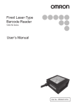
Download 形 V400-R2CF
Transcript
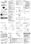
安全上の要点
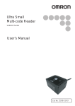
形
V400-R2CF□
マルチコ−ドリ−ダ
取扱説明書
このたびは、本製品をお買い上げいただきまして、
まことにありが
とうございます。
ご使用に際しては、次の内容をお守りください。
・電気の知識を有する専門家が扱ってください。
・この取扱説明書をよくお読みになり、十分にご理解のうえ、正し
くご使用ください。
・この取扱説明書はいつでも参照できるように大切に保管くださ
い。
製品を安全に使用するため、以下のことを守ってください。
1.
設置環境について
・引火性、爆発性ガスの環境では使用しないでください。
・腐食性ガス、可燃性ガスがある場所では使用しないでください。
・塵埃、塩分、鉄粉がある場所では使用しないでください。
・水、油、化学薬品の飛沫やミスト雰囲気がある場所では使用しないでください。
・CRTの点滅等、外乱光の影響を受ける場所では使用しないでください。
・屋外に設置して使用することは避けてください。
・操作、保守の安全性を確保するため、高圧機器や動力機器から離して設置
してください。
2.
電源、配線について
・ノイズ耐性・絶縁耐性を確保するために駆動用電源として形S8VS-01505
(オムロン製)
を必ずご使用ください。
・定格電圧
(5V±10%)
を超える電圧や交流電源を接続しないでください。
・電源の逆接続はしないでください。OK/NG出力信号(オープンコレクタ)
は負荷を短絡しないでください。
・負荷は定格以下で使用してください。
・ケーブル類の着脱は、必ず電源を切った状態で行ってください。通電中に着
脱すると故障の原因になります。
・高電線、動力線と本製品の配線は別配線としてください。同一配線あるいは
同一ダクトにすると電磁誘導を受け、誤動作あるいは破損の原因になります。
・取り付けネジは本書で記載している規定のトルクで締め付けてください。
・静電気による破損を防ぐため、端子部分やコネクタ内部の信号線に触れる場合は、
リストストラップなどを使用して帯電防止措置を行ってください。
・電源線の長さをできるだけ短くなるように
(長さ3m未満)配線してください。
3.使用ラベルについて
・表面の光沢度が高いラベルの場合は、照明用LEDの正反射のため読み取り難く
なることがあります。
その場合、
ラベルに対してスキュー角を15°
程度に傾けて読み取
りを行ってください。
読取り窓部前面には、
ほこりや油滴などがつかないような場所に設置してください。
万一付いた場合は、次のように清掃してください。
・大きなごみ、
ほこりはブロアブラシ(カメラレンズ用)で吹き飛ばしてください。呼気で吹
き飛ばすことは避けてください。
・小さなごみ、
ほこりは柔らかい布(レンズクリーナなど)にアルコールを少量含ませて、
ていねいに拭き取ってください。
強く拭くことは避けてください。読取り窓にきずが付くと読取り不良の原因となります。
All Rights Reserved.
形V400-R2CF65
形V400-R2CF125
RS-232C
NPN オープンコレクタ出力(ただし、
ケーブル加工が必要)
メニューシート読取り方式または ホストコマンド方式
外部トリガ(トランジスタ入力)
コマンドによるトリガ(RS-232C)
本体のスキャンボタンによるテスト読取りのトリガ
OK/NG 信号
読取り成功時はOK 信号がON
登録ラベル以外のラベル読取り成功時はNG信号がON
表示LED
ブザー
電源電圧
消費電流
周囲温度範囲
周囲湿度範囲
周囲雰囲気
外乱光
耐振動
読取り成功時はOK LED(緑)が点灯
読取り成功をブザー音で通知(消音可能)
DC4.5∼5.5V
動作時:265mA 以下 待機時:70mA 以下
動作時:0∼+45℃ 保存時:−10℃∼+60℃
20∼85%RH(ただし、
氷結・結露しないこと)
腐食性ガスのないこと
蛍光灯:10,000lx 以下 太陽光:100,000lx 以下
10∼150Hz 片振幅0.35mm 3 方向
(X/Y/Z)
各8 分10 回
電源電圧
環境仕様
保護構造
質量
外形サイズ
本体のみ
付属品込み
梱包重量
本体サイズ
梱包サイズ
入出力コネクタ
コード長
コード最小曲げ半径
付属品
材質・色
本製品の起動を確認後、上位機器との通信を行ってください。
また、本製品
の起動時には、上位インターフェースから不定な信号が出る可能性があります
ので、初期動作時はご使用機器の受信バッファをクリアするなどの処理を実
施してください。
* 1 8 9 9 6 6 0 - 4 C *
形式
インタ−フェ−ス 通信仕様
OK/NG 出力
機能設定方式
機能仕様
読取りトリガ
4.読取り窓の清掃について
3.
上位機器との通信について
© OMRON Corporation 2013
■一般仕様
ケース
読取り窓
ケーブル
取付金具
IP65(IEC60529 規格)
約90g
約200g(取付金具,
ネジを含む)
約280g(梱包箱含む)
約41.1(W)×33(D)×24(H)mm
約245(W)×110(D)×40(H)mm
丸型DIN コネクタ
約1.5m
約23mm
取扱説明書、
メニューシート、
取付金具、
M2×6 ネジ
(2 本)、
M5×10 ネジ(2 本)
PC、
PET、
黒色
PMMA、
透明
PVC、
黒色
SUS304、
銀色
4.
その他
本マルチコ−ドリ−ダは、以下の安全規格に準拠しています。
LED安全規格
:IEC 62471-1:2006 リスク免除グル−プ
EN 規格(CE マーク):EN55022/EN55024
使用上の注意
製品が動作不能、誤動作、
または性能・機器への悪影響を防ぐため、以下のこと
を守ってください。
次のような場所には設置しないでください。
・周囲温度が仕様で定められている範囲を超える場所
・温度が急激に変化する場所(結露する場所)
・相対湿度が仕様で定められている範囲を超える場所
・振動や衝撃が直接加わる場所
・強い外光乱(レーザ光、
アーク溶接光、紫外光など)
があたる場所
・直射日光があたる場所や暖房器具のそば
・強磁界、強電界がある場所
また、定格に記載している保護構造上、次の場所には設置しないでください。
・腐食性ガス、可燃性ガスがある場所
・塵埃、塩分、鉄粉がある場所
・水・油・化学薬品の飛沫やミスト雰囲気がある場所
●警告表示
警告
安全を確保する目的で直接または間接的に人体を検出する用途
に本製品は使用できません。
人体保護用の検出装置として本製品を使用しないでください。
1.25
光軸
1.
設置場所について
禁止
一般的な禁止を示します。
2-M2 深さ 3 max
φ20
●図記号の説明
5.法規と規格
24
18.4
2-M2 深さ 3 max
35.1
16
37
10.65
警告
正しい取扱いをしなければ、この危険のために、軽
傷・中程度の傷害を負ったり、万一の場合には重症
や死亡にいたる恐れがあります。また、同様に重大
な物的損害を受ける恐れがあります。
41.1
光軸
22
●警告表示の意味
10.65
33
●安全に使用していただくための表示と意味について
この取扱説明書では、形V400-R2を安全にご使用いただくために、
ここで示した
注意事項を次のような表示と記号で示しています。
注意事項は安全に関する重大な内容を記載しています。
必ず守ってください。表示と記号は次のとおりです。
■外形寸法
(形V400-R2CF□)
18
安全上のご注意
・原子力や、人命に関わる安全回路には使用しないでください。
・本体の分解、修理、改造、加圧変形、焼却したりしないでください。
・廃棄するときは、産業廃棄物として処理してください。
・異臭がする、本体が非常に熱くなる、煙が出るなどの異常が起こった場合、すぐ
に使用を中止し、電源を切った状態で当社支店・営業所までご相談ください。
コネクタ
ビニル絶縁丸型コード φ3.8 10芯 黒
標準長さ 1.5m
[ 単位 : mm ]
2.
電源及び接続・配線について
・駆動電源として形S8VS-01505(オムロン製)を必ずご使用ください。
・高圧機器の設置されている場所には取り付けないでください。
・配線後は電源を投入する前に、電源の正誤、負荷短絡などの誤接続の有無、負荷
電流の適否について確認を行ってください。誤配線などで故障する恐れがあります。
●取付金具取付図
(V400-R2CF□)
■商品の外観と各部の名称
●取付金具単体図
(付属品)
●形V400-R2CF□
(フロントビュータイプ)
.6 φ5.2
2-R2
2.6
12
10.65
本体ケーブル
12
25
12
スキャンボタン
ブザー音孔
2-R
47
26.45
読取り確認LED
10
2-R
30
3
R1
R1
1.25
.6
47
30°
R15
30°
0.4
60°
読取り面
2.2
φ
φ
5.2
光軸
38.1
R36.2
■配線図
形V400-R2CF□
2-R
取付穴寸法
■取付金具の装着
■設置場所への取付け
本体に取付け金具を装着します。(M2 ネジ,
締め付けトルク 0.15N.m)
(ピン配列)
R2
2-
1.1
13
15°
15°
.1
R1
2-
8.9
28
.1
R35
2-M5
30°
R34
φ2.2
設置場所に取付けます。(M5 ネジ,
締め付けトルク 2.3N.m)
M2×6ネジ
M2×6ネジ
コ ネ ク タ 部 (DIN:8P プ ラ グ)
ホシデン株式会社製
形TCP1394-715267(T y p e A )
線材色 ピン番号
緑
白
灰
青
茶
−
黒
赤
黄
橙
信号名
SD
1
2
RD
RS
3
4
CS
TRIG
5
6
NC
S GND
7
8
VCC
−(注) OK
−(注) NG
役割
2次元コードリーダ
送信パラメ−タ
受信パラメ−タ
送信要求
送信可
外部トリガ信号
無接続
0V
電源
読取OK出力
信号方向
外部
外部
外部
外部
注)
OK,NG出力線はDIN8ピンコネクタには接続していません。OK,NG使用
時はケ−ブルをカットしてご使用ください。
■外部トリガ信号の入力回路
Vcc
TRIG
■性能仕様
形式
適用コ−ド(※1)
Von/off
項目
読取り性能(※2)
最小値
最大値
トランジスタON時端子電圧Von
0V
0.8V
トランジスタOFF時端子電圧Voff
2V
Vcc+0.5V
■READ OK/NG信号の出力回路
OK/NG
内部回路
SG
項目
出力体系
定格負荷
OFF時漏れ電流
ON時残留電圧
仕様
NPNオ−プンコレクタ
DC24V 30mA
0.5mA以下
0.3V以下
当社商品は、一般工業製品向けの汎用品として設計製造されています。従いまして、次に
掲げる用途での使用を意図しておらず、
お客様が当社商品をこれらの用途に使用される際
には、当社は当社商品に対して一切保証をいたしません。
ただし、次に掲げる用途であって
も当社の意図した特別な商品用途の場合や特別の合意がある場合は除きます。
(a) 高い安全性が必要とされる用途
(例:原子力制御設備、燃焼設備、航空・宇宙設備、鉄
道設備、昇降設備、娯楽設備、医用機器、安全装置、
その他生命・身体に危険が及び
うる用途)
(b) 高い信頼性が必要な用途
(例:ガス・水道・電気等の供給システム、24時間連続運転
システム、決済システムほか権利・財産を取扱う用途など)
(c) 厳しい条件または環境での用途
(例:屋外に設置する設備、化学的汚染を被る設備、
電磁的妨害を被る設備、振動・衝撃を受ける設備など)
(d) カタログ等に記載のない条件や環境での用途
取付け金具
内部回路
SG
ご承諾事項
2-M5×10
上位機器
読取NG出力
外部トリガ信号
取り付け面
バーコード
形V400-R2CF65
形V400-R2CF125
WPC(JAN/EAN/UPC), Codabar(NW-7), ITF, Industrial2of5(STF), Code39, Code93, Code128,
GS1-128(EAN-128), GS1-Databar(RSS-14), GS1-Databar Limited(RSS Limited),
GS1-Databar Expanded(RSS Expanded), GS1-Databar Composite(RSS Composite)
2 次元コード(※3)
QR Code, DataMatrix(ECC200), MicroQR Code,
PDF417, MicroPDF417, AztecCode, MaxiCode, Codablock-F
読取り桁数
最大の制限なし(バー幅と読取距離により異なります。)
光源
エイミング光源
最小分解能
赤色LED×2(波長617nm)
緑色LED×1(波長528nm)
バーコード:0.076mm 2次元コード:0.127mm
撮像素子
有効画素数
焦点距離(WD)
視野
スキュー角(α)
ピッチ角(β)
チルト角(γ)
モノクロCMOS
752×480 画素
65mm
約48×31(WD=65mm)
±50°
±50°
±180°
湾曲読取り(R)
R≧20mm(UPC12 桁)
*(a)から(d)に記載されている他、本カタログ等記載の商品は自動車
(二輪車含む。以下同
じ)
向けではありません。自動車に搭載する用途には利用しないで下さい。自動車搭載
用商品については当社営業担当者にご相談ください。
*上記は適合用途の条件の一部です。当社のベスト、総合カタログ、データシート等最新版
のカタログ、
マニュアルに記載の保証・免責事項の内容をよく読んでご使用ください。
インダストリアルオートメーションビジネスカンパニー ●製品に関するお問い合わせ先
お客様相談室
0120-919-066
バーコード:0.127mm 2次元コード:0.212mm
クイック
オムロン
携帯電話・PHS・IP電話などではご利用いただけませんので、
下記の電話番号へおかけください。
電話
055-982-5015(通話料がかかります)
■営業時間:8:00∼21:00 ■営業日:365日
125mm
約93×59(WD=125mm)
※1 当社の評価基準における読み取り対応可能コードです。
ご使用に際しては、
お客様の使用条件で評価をお願いします。
※2 読取り性能は特に指定なき場合、
角度α=0°
、
β=+15°
、
γ=0°
、
R=∞、環境照度100∼200lx、読取り率90%以上で規定します。
※3 QR コードは(株)デンソーウェーブの登録商標です。
●FAXやWebページでもお問い合わせいただけます。
FAX
055-982-5051 / www.fa.omron.co.jp
●その他のお問い合わせ
納期・価格・サンプル・仕様書は貴社のお取引先、または貴社
担当オムロン販売員にご相談ください。
オムロン制御機器販売店やオムロン販売拠点は、Webページで
ご案内しています。
A v 2 0 1 4 年 7月
V400-R2CF□
Multi-code Reader
INSTRUCTION SHEET
Thank you for selecting OMRON product. This sheet primarily describes precautions required in installing and
operating the product.
Before operating the product, read the sheet thoroughly to
acquire sufficient knowledge of the product. For your convenience, keep the sheet at your disposal.
・Check that the product has started up, and then start communication
with upper equipment.
・Indefinite signals may be generated from the upper interface while
the product starts up. Clear the receive buffer of the devices before
starting initial operation.
Manufacturer:
Omron Corporation,
Shiokoji Horikawa, Shimogyo-ku,
Kyoto 600-8530 JAPAN
●Meanings of safety symbols
WARNING
●Meanings of alert symbols
Prohibition
Indicates general prohibition.
●Warning display
WARNING
To ensure safety, this product should not be used to
detect a human body either directly or indirectly.
Do not use this product as a detection device to protect
the human body.
Precautions for Safe Use
Observe the following precautions to ensure safe use of the product.
1. Installation Environment
・Do not use the product in environments containing flammable or
explosive gases.
・Do not use the product in environments containing corrosive or
combustible gases.
・Do not use the product in environments containing dust, salt, or
metallic powders.
・Do not use the product in environments containing droplets, water or
mist, oil or chemical agents.
・Do not use the product in environments that may be affected by a
CRT's flashing or other ambient light.
・Do not install or use the product outdoors.
At operation and storage : 20 to 85% RH
(with no icing or condensation)
IP65(IEC60529 standard)
Main body only
Approximately 90 g
Main body
Added accessories
Approximately 200g(including mounting bracket
and screws)
Packing weight
Approximately 280g(including packing)
Main body Dimension
Approximately 41.1(Dimensions W)×33(D)×24(H)mm
Packing Dimension
Approximately 245(W)×110(D)×40(H)mm
Input connector
Round DIN connector
Code minimum bending radius
Approximately 23mm
Approximately 1.5m
Operation manual、menu sheet、mounting bracket、
M2×6screws(two)、M5×10screws(two)
Case
PC、PET color : black
Cable
PVC color : black
Reading window
PMMA color : transparence
SUS304 color : silver
■External Dimension(V400-R2CF□)
10.65
41.1
OPTICAL AXIS
24
18.4
2-M2 DEPTH 3 max
35.1
2-M2 DEPTH 3 max
1.25
OPTICAL AXIS
2. Power supply, connection, and wiring
・Be sure to use S8VS-01505 (made by OMRON) as a driving
power supply.
・Do not install the product in a location where a high-voltage device
is installed.
・After connecting the cables, check that the correct power supply
is used, that there is no load short-circuiting or other inappropriate
connections, and that the load current is correct before turning
the power ON. Faulty wiring may be the cause of failure.
[ UNIT : mm ]
16
37
CONNECTOR
VINYL INSULATED ROUND CORD
DIA3.8 10CORES BLACK
STANDARD LENGTH 1.5m
■Part Names and Functions
●V400-R2CF□
.4
R10
OK/NG LED
10
2-R
SCAN button
Buzzer stop
30
φ5.2
2.6
12
10.65
2-R
Main cable
12
25
12
During operation:265mA or less
During standby:70mA or less
At operation:0∼+45℃ At storage:−10∼+60℃
Mounting bracket
47
26.45
DC4.5∼5.5V
Environmental Ambient temperature
specifications Ambient humidity
Material・
Color
R15.6
.6
Notifies a successful reading with a buzzer sound
(Muting available)
Power supply Power voltage
specification Consumption
current
Weight
●Mounting bracket(Accessory)
2-R2
3
OK LED(green) illuminates to indicate a successful read
Buzzer
Accessories
30°
30°
R1
1.25
Indication
LED
Vibration Resistance 10 to 150 Hz, single amplitude: 0.35 mm, X/Y/Z
(destructive)
directions 8 min each, 10 times
60°
47
OK signal is turned on to indicate a successful read
NG signal is turned on to indicate a successful read
a non-registered label
Code length
The product must not be installed in a place:
・where ambient temperature is outside the range defined in the
specifications,
・where a rapid temperature change (dew condensation) occurs,
・where ambient humidity is outside the range defined in the
specifications,
・where direct vibration or shock may affect the product,
・where exposed to intense ambient light (laser, arc welding, or UV
light),
・where exposed to direct sunlight or heat from heating appliances, and
where a strong magnetic or electric field exists.
Because of the protection rating described in the manual, avoid
using locations containing:
・corrosive or combustible gases,
・dust, salt, or metallic powders,
・droplets, water mist, oil or chemical agents.
●Attachment Dimension V400-R2CF□
External trigger (Transistor input)
Trigger by command(RS-232C)
Trigger a test reading by pressing the SCAN button
on the product
OK / NG
signals
Dimensions
1. Installation location
Indicates a potentially hazardous situation
which, if not avoided, will result in
minor or moderate injury, or may result in
serious injury or death. Additionally,
singnificant property damage may occur.
Functional
Reading
specifications trigger
DIA20
Precautions for Correct Use
Always observe the following precautions to prevent operation
failures, malfunctions, and adverse effects on performance and
equipment.
NPN open collector output (Necessary to cable shaping)
Menu sheet reading method or host command method
22
In this operation manual, precautions are indicated using the following
symbols and signal words to ensure safe use of the V400-R2CF�.
The precautions indicated by these symbols and signal words are
important to ensure safety and must be observed.
The symbols and signal words are as follows:
OK/NG outputs
Function setting method
Degree of protection
This product complies with the following standards.
LED safety standard : IEC 62471-1:2006 Risk Exempt Group
EN standard(CE mark) : EN55022/EN55024
●Meanings of safety symbols
V400-R2CF125
RS-232C
Ambient light resistance Fluorescent light:10,000lx max. Sun light:100,000lx max.
5. Regulations and Standards
Safety Precautions
V400-R2CF65
Communicatio
n specification
Ambient atmosphere No corrosive gas
A급 기기(업무용 방송통신기자재)
이 기기는 업무용(A급) 전자파적합기기로서 판매자
또는 사용자는 이 점을 주의하시기 바라며,가정외의
지역에서 사용하는 것을 목적으로 합니다.
・Do not use the product in a safety circuit for nuclear or life-support
systems.
・Never attempt to disassemble, repair, modify, deform by applying
pressure, or burn the product.
・Dispose of the product as industrial waste.
・If the product becomes extremely hot, or abnormal odors or smoke
are emitted, stop using the product immediately, turn the power OFF,
and consult with your OMRON representative.
All Rights Reserved.
Interface
33
© OMRON Corporation 2013
4. Other
Model
5. Notice for Korea Radio Law
18
TRACEABILITY INFORMATION:
Importer in EU:
Omron Europe B.V.
Wegalaan 67-69
2132 JD Hoofddorp,
The Netherlands
3. Communication with Upper Equipment
■Specifications
10.65
model
・Use a wrist strap or other similar device to avoid electrostatic
・For the purpose of ensuring safe operation and maintenance, do not
install the product close to high-voltage devices or electrically powered charge when you touch terminals and signal lines within a connector,
and to avoid damage due to static electricity.
devices.
・Try to keep the length of the power cable to a minimum (less than 3 m).
2. Power Supply and Wiring
・To assure noise and insulation resistance, be sure to use
3. Labels
S8VS-01505 (made by OMRON) as a driving power supply.
・For labels with a highly gloss surface, reading errors may occur
・Do not connect a voltage or AC power supply that has a voltage
because of regular reflection of the LED light. If this occurs,
exceeding the rating voltage (5 V+/-10%).
provide a skew angle of 15° against the label.
・Avoid reverse connection of power supply. Do not short circuit a
load on OK/NG output signal (open collector).
4. Cleaning of the reading window
・Avoid applying a load that exceeds the rating.
Install the product so that the front area of the reading window is
・Be sure to turn the power OFF before connecting or
free of dust and oil droplets.If dust or oil droplets are found, clean
disconnecting a cable.
the surface using the following method.
Connecting or disconnecting a cable while the power is ON may
・Blow large particles off using a blower brush (for camera lenses).
cause failure.
Do not blow using your own breath.
・Connect different cables from high-voltage or power cables to
・Gently wipe off small particles using a soft cloth(lens wiper)
the product. If the same cable or duct is used, electromagnetic
moistened with a small amount of alcohol. Avoid vigorous
induction may result, which may result in malfunction or damage.
wiping. Scratches on the reading window may result in read in
・Tighten the fixing screws at the torque specified in this manual.
errors.
φ
φ
5.2
OPTICAL AXIS
Reading window
2.2
38.1
R36.2
13
15°
R35
28
15°
.1
2-M5
30°
R34
φ2.2
■Wiring and Connection
●V400-R2CF□
1.1
2-R
■Installation of mounting bracket
(Pin alignment)
Attach the mounting bracket to the reader (M2 screw,
Tightening torque:0.15N.m)
M2×6 screw
M2×6 screw
C o n n e c t o r p a r t (DIN: 8P plug )
Made by Hosiden Corporation
TCP1394-715267 (Type A)
Wire Pin No.
color
Green
1
White
2
Gray
3
Blue
4
Brown
5
−
6
Black
7
Red
8
Yellow −(Note)
Orange −(Note)
Signal
name
SD
RD
RS
CS
TRIG
NC
S GND
VCC
OK
NG
Function
Transmission data
Received data
Transmission request
Transmission allowed
External trigger signal
Not connected
0V
Power supply
READ OK output
Reader
Signal direction
Upper equipment
External
READ NG output
TRIG
Internal
circuit
Von/off
SG
Item
Minimum value
Terminal voltage Von when a
0V
transistor is turned on
Terminal voltage Voff when a
2V
transistor is turned off
■READ OK/NG signal output circuit
Maximum value
0.8V
Vcc+0.5V
OK/NG
SG
Item
Output system
Rated load
Leak current at OFF
Residual voltage at ON
Specification
NPN open collector
24 VDC 30 mA
0.5 mA or less
0.3 V or less
Install the Code-Reader with mounting bracket to the mounting surface.
(M5 screw,Tightening torque: 2.3N.m)
Mounting Surface
2-M5×10
Mounting bracket
Model
Applicable
codes
(※1)
Vcc
External trigger signal
■Installation at the mounting surface
Internal
circuit
Reading
performance
(※2)
Bar code
2D code (※3)
Number of reading digits
Light source
Aiming light
Minimum resolution
Image capture device
Effective pixels
Working distance(WD)
Field of view
Skew angle (α)
Pitch angle (β)
Tilt angle (γ)
Reading of bar codes
on curved surface(R)
Suitability for Use
Omron Companies shall not be responsible for conformity with any standards,
codes or regulations which apply to the combination of the Product in the
Buyer’s application or use of the Product. At Buyer’s request, Omron will
provide applicable third party certification documents identifying ratings and
limitations of use which apply to the Product. This information by itself is not
sufficient for a complete determination of the suitability of the Product in
combination with the end product, machine, system, or other application or
use. Buyer shall be solely responsible for determining appropriateness of the
particular Product with respect to Buyer’s application, product or system.
Buyer shall take application responsibility in all cases.
■Specifications
External
External
External
Note)The OK and NG output lines are not connected to the DIN
8-pin connector. To use the OK and NG outputs, cut the cables.
■External trigger signal input circuit
2
Mounting hole dimension
R
2-
1
1.
R
2-
8.9
V400-R2CF65
V400-R2CF125
WPC(JAN/EAN/UPC), Codabar(NW-7), ITF, Industrial2of5(STF), Code39, Code93, Code128,
GS1-128(EAN-128), GS1-Databar(RSS-14), GS1-Databar Limited(RSS Limited),
GS1-Databar Expanded(RSS Expanded), GS1-Databar Composite(RSS Composite)
QR Code, DataMatrix(ECC200), MicroQR Code
PDF417, MicroPDF417, AztecCode, MaxiCode, Codablock-F
No upper limit (depends on bar width and reading distance)
Two red LEDs (wave length:617nm)
One green LEDs(wave length:528nm)
Bar code:0.076mm 2D code:0.127mm
Monochrome CMOS
752×480 pixels
65mm
Approximately 48×31(WD=65mm)
NEVER USE THE PRODUCT FOR AN APPLICATION INVOLVING
SERIOUS RISK TO LIFE OR PROPERTY WITHOUT ENSURING THAT THE
SYSTEM AS A WHOLE HAS BEEN DESIGNED TO ADDRESS THE RISKS,
AND THAT THE OMRON PRODUCT(S) IS PROPERLY RATED AND
INSTALLED FOR THE INTENDED USE WITHIN THE OVERALL
EQUIPMENT OR SYSTEM.
See also Product catalog for Warranty and Limitation of Liability.
OMRON Corporation
Tokyo, JAPAN
Bar code:0.127mm
2D code:0.212mm
125mm
Approximately 93×59(WD=125mm)
±50°
±50°
±180°
R≧20mm(UPC12 digit)
※1 These are the code types supported based on Omron’s read capability validation standard.
It is recommended that the customer do its own validation in its actual work environment.
※2 Unless otherwise specified , the reading performance is defined with angle α=0°,β=+15°,γ=0°,R=∞; illuminance : 100 to 200 lx(on label side);
lightning: three band inverter fluorescent lamp; reading rate: 90% or more.
※3 QR Code is a registered trademark of DENSO WAVE INCORPORATED in JAPAN and other countries.
Industrial Automation Company
Contact: www.ia.omron.com
Regional Headquarters
OMRON EUROPE B.V.
Sensor Business Unit
Carl-Benz-Str. 4, D-71154 Nufringen, Germany
Tel: (49) 7032-811-0/Fax: (49) 7032-811-199
OMRON ELECTRONICS LLC
2895 Greenspoint Parkway, Suite 200
Hoffman Estates, IL 60169 U.S.A.
Tel: (1) 847-843-7900/Fax: (1) 847-843-7787
OMRON ASIA PACIFIC PTE. LTD.
No. 438A Alexandra Road # 05-05/08 (Lobby 2),
Alexandra Technopark,
Singapore 119967
Tel: (65) 6835-3011/Fax: (65) 6835-2711
OMRON (CHINA) CO., LTD.
Room 2211, Bank of China Tower,
200 Yin Cheng Zhong Road,
PuDong New Area, Shanghai, 200120, China
Tel: (86) 21-5037-2222/Fax: (86) 21-5037-2200
D s O ct, 2 0 1 4


