1
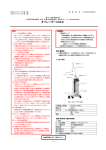
関連製品
特長 Features
1.
■仕様
形式/Model
表示
Display
スポットUV照射装置
Spot UV Curing Equipment 点UV照射装置
機能
Function
照度分布出力
Illuminance distribution output
サンプルレート
Sample rate
スポットキュア シリーズ
R
通信仕様
Communication
specifications
電源/Power supply
寸法(mm)/Dimensions
重量(g)/Weight
特長 Features
■仕様
形式/Model
表示
Display
機能
Function
測光範囲
Range of measurement
UVD-365PD使用時
UVD-405PD使用時
アナログ出力
Analog output
電源
Power supply
寸法(mm)/Dimensions
重量(g)/Weight
13
プで
ラン た。
衰
低減
した
まし
0W 能にし を追求
25
さ
可
力
易
も
高出
入力
使い
0W
由。
0
自
2
。
新型
き
横置 ・ボディ タイプ
/
縦
コ
ト
p
たエ -9」。
パク
Lam e
慮し
コン
P
S
配
:
W
s
l
に
「
0
e
b
ア
r
5
able
a
環境 トキュ
atu tion 2 elect
vail
e
A
F
ッ
9
ua put S tures
スポ
SPtten
In
os
r
-A
P
RE
CU t Low Powe rvice
T
stem
u
e
O
p
l Sy
SP -Outp Lam ntal S
a
c
i
g
h
o
Hig /250W Horiz
colo
W and
dE
0
e
0
d
2
l
n
ody
tica
-Mi
Ver pact B nment
Com Enviro
New
「高照度・低減衰」
「使い易さ」に加え、環境に配慮 した“SP-9”新登場
New User-friendly SPOT-CURE Model SP-9 Heir to the High Power and Low Attenuation of Model SP-VII
さらにコンパクトに、使い易く。
「現場を一番知っている」スポットキュアだからできた新機能。
More Compact, with User-friendly New Features That Only SPOT-CURE Can Deliver.
1
省エネに貢献するランプ電力切替機能
照度設定の自由度が広がるランプ電力切替機能(200W/250W)
を搭載。200W点灯時の電力は、250W時に比べ、約20%ダウン
となり、省エネに貢献します。
2
5
環境への配慮
本体内部の基板の鉛フリー化を実現しました。また、日本語・英語・
中国語の取扱説明書もペーパーレス化(CD-ROM)しました。
(特注品は除く)
縦位置・横位置どちらでも使用可能なコンパクトボディ
6
取り外し可能な外部制御端子
縦型・横型どちらにも設置可能なユーティリティ・デザイン。「小さな
フット・プリントで狭いスペースに」「二段積み」など、ラインの「す
き間」にも効率よく収まります。
従来の「SP-7」同様、外部制御端子が工具なしで結線でき、作業性
に優れた着脱式のコネクタを継続採用しました。狭いスペースに設
置した装置の設定変更も容易です。外部調光機能も継続採用してい
ます。
Lamp Power Switch Function Contributing to Power-Saving
Environment-Minded Technology
Compact Body, Usable in Vertical and Horizontal Positions
Detachable External Control Terminals
Lamp Power Switch function (200W/250W) that expands the degree of freedom of irradiance
setting. The power consumption of the 200W lamp is about 20% less than that of the 250W
lamp.
All PC boards in the SP-9 are free of lead. User's manuals in Japanese, English, and Chinese
are distributed in compact disks (CD-ROM).
(Some user's manuals for custom-ordered products are print-out manuals.)
Model SP-9 can be installed either vertically or horizontally. In addition to having a small
footprint, the SP-9 is stackable for efficient installation within a small space on a production line.
The SP-9 like the previous
SP-7 uses newly designed,
detachable external control
terminals for easy connection
without a tool. These
terminals enable easy
changing of the settings of an
SP-7 unit installed in a narrow
space.
3
左右どちらからでもランプ交換可能
4
より使いやすくなった操作パネル
筐体の左右両側の扉から、ランプ交換が可能。本体を設置場所から
動かさず、効率的に交換作業ができます。
従来の「SP-7」のフラットパネルをベースに、より使いやすい操
作パネルに改良しました。シャッタタイマ設定や調光など、必要な
照射条件を入力できます。
Lamp Replaceable from Either Side
More User-Friendly Operator Panel
The SP-9 is equipped with a door on both the left and right sides of the cabinet. You can
replace the lamp from any side of the cabinet without moving the cabinet.
The operator panel of the SP-9 has been improved from the flat panel of the SP-7 and become
more user-friendly. You can easily enter necessary light conditions such as shutter timer
adjustment and light control.
7
ワールドボルテージ対応
8
従来機種とパーツ互換
AC90V∼264Vまで、各入力電圧に自動的に対応します。海外で
使用する場合も改造や切替の必要はありません。
ランプ、ファイバユニットは、従来の「SP-7」と互換可能。機種更
新時にもムダなく利用できます。(フィルター類は互換できません)
シャッタタイマ設定
調光
Operable at Any Voltage
Conventional Parts Are Usable
Shutter timer adjustment
Light control
The SP-9 automatically handles input voltages ranging from 90 to 264 VAC. No modification or
switching is required.
Lamp and fiber unit of the SP-9 are compatible with those of the SP-7, thus saves the cost of
renewal.
通算点灯時間
Lamp operating time
ランプ交換時間設定
Lamp replacement time setting
用途例 Sample Applications
光ディスクピックアップ
HDD
CCD
Optical Disk Pickup
●ランプ点灯中や消灯直後は、ランプやランプハウス周辺部は熱くなっているため、絶対に触
れないください。火傷の原因となります。
対物レンズの接着
●ランプのガラス部は、直接素手で触れないようご注意ください。
● Do
not touch the lamp, lamp house, or its periphery because it is extremely hot while the lamp is on or
immediately after the lamp is turned off. Otherwise you will get your fingers burnt..
●Do not touch the lamp bulb directly with bare hands.
Object lens bonding
ランプ電力切替
エラー表示
Lamp power switching
Error indicafion
レシピモード
Recipe mode
2
ヘッド部接着
モータ部の組立
ガラスカバー接着
内部光学系の接着・固定
Head bonding
Motor assembling
Glass cover bonding
Bonding and fixing internal optical system
3
寿命末期まで高照度を維持する“低減衰UVランプ”
。スポットキュア最大の特長です。
Low-Attenuation UV Lamp That Maintains High Irradiance Throughout Its Life - Greatest
■ 照度劣化特性(例:250W点灯時)
Irradiance Attenuation Characteristics (Ex. when the 250W lamp is on)
ワンタッチフォーカスシステム
100
相対放射照度(%)
Relative radiation irradiance (%)
スポットキュア専用に開発したDeepUVランプは、照度減衰を大幅に抑えた長
寿命設計。2000時間使用後のUV照度保証80%は、他社製品と比べていただ
ければ、その価値をご理解いただけるはずです(縦置き時)。この優れた光源特性
により、SP-9は、初期から寿命末期までUV照度の変化が少なく、安定したライ
ン稼働を実現します。
さらに、素早い立ち上がり・光学調整不要なワンタッチフォーカスシステムなど、
現場のニーズに即応した特性と機能を備た
“理想のUVランプ”となっています。
Feature of SPOT CURE
縦置き時
Vertical posture
80
ランプを固定ベースに押し込み、ノブを押すだけで光軸が合った状
態でランプが固定されます。後はリード線を端子に固定するだけ。
工具なしで、30秒で取り付け完了です。次のランプ交換時期まで、
光軸調整は一切不要です。
横置き時
Horizontal posture
60
40
20
The deep UV lamp developed especially for the SPOT-CURE series features long life while greatly
minimizing attenuation of irradiance. Only USHIO has achieved a guaranteed UV irradiance of 80% after
2000 hours of use (during operation of the lamp vertically mounted). This excellent characteristic allows the
SP-9 to operate on a production line under stable conditions with minimal change in UV irradiance from the
beginning to the end of the lamp life.
This is an ideal UV lamp provided with features immediately meeting field needs, such as quick-start
capability and a quick-focus system that requires no optical adjustment.
0
0
500
1000 1500
2000
2500
点灯時間(h)Service Time
Quick-Focus System
3000
Just push the lamp into the lamp base and press the knob. The lamp is secured with its optical
axis aligned. Then connect the lead wires to the terminals. You can complete lamp setting in 30
seconds without any tool. No optical axis adjustment is required until next replacement of the
lamp.
低温処理
Low-temperature Curing
UV樹脂硬化に不要な熱線を後方に透過し、紫外線を効率よく集光す
るコールドミラー。さらに低温プロセスが求められる場合は、熱線カ
ットフィルタや365nmバンドパスフィルタ※が使えます。
※365nmバンドパスフィルタの使用により、波長はLED光源とほぼ同一に
なります。ワークや接着剤などの対象物にあわせて波長を可変できるのが、
ランプ光源の強みです。
Also available are a cold mirror that transmits unwanted heat rays (not required for UV curing)
farther heat-ray a cut filter or 365-nm band-pass filter(*) if cold curing is necessary.
*The 365-nm band-pass filter makes the wavelength almost equal to that of LED rays. The merit of the lamp
light source is to vary UV wavelengths according to the objects (works or adhesives) to be cured.
0∼100%の調光機能
-Hour Service
0-to-100% Light Control
シンプルなメカ絞り方式の調光システムを採用。0∼100%まで、
1%刻みで確実に調光します。
目盛値と照度はほぼリニアに対応します。
-hour service
UVランプによって発生するオゾンについて Ozone generated by UV lamp
(for radiation of 500 mW/cm2)
SP9-250DB/SF-101AQ
Light can be controlled in increments of 1% from 0% to 100% by a light control system using a
simple mechanical diaphragm the scale value corresponds almost linearly to the irradiance.
SP9-250DB/SF-101AQ
■ 調光度合いと目盛り値の関係(目安)
Relationship between light control rate and scale value (standard)
ランプ冷却ファン出口にて実測 Measured at the air outlet of lamp cooling fan.
安 定 時
When turned on
When stabilized
オゾン濃度
0.01ppm以下
0.01ppm以下
Ozone Concentration
Max. 0.01 ppm
Max. 0.01 ppm
■ 照度立上がり特性(例)
Irradiance Rise Characteristics(Example)
相対放射照度(%)
Relative radiation irradiance (%)
100
※空気中オゾン濃度は厚生労働省安全衛生基準「0.1ppm」以下。
安心してご使用いただけます。
* Safety and Health Standards of the Ministry of Health, Labour and Welfare:
The ozone concentration in atmospheric air shall be 0.1 ppm or less
Electrode Structure for Minimizing
Irradiance Attenuation
This structure prevents burn-out
of the cathode tip, deformation
and movement of the luminous
point, condensation loss and
focus shift by supplying emitters
from the inside of the cathode.
20
40
60
目盛り Scale
80
100
*The temperature rise depends upon materials, sizes, colors, and shapes of objects to be illuminated.
波長選択 Wavelength selection
1
2000時間使用後の電極部比較
陰極内部から常にエミ
ッタを供給することに
より、先端部の消耗を
防ぎ、輝点の変形・移
動による集光ロス焦点
ズレを防ぎます。
Room temp. of 28 degrees C
0
0
照度減衰を抑える電極構造
With 365nm band-path filter
相対放射照度(%)
Relative radiation irradiance
点 灯 時
100
90
80
70
60
50
40
30
20
10
2
3
4
5
時間(分)Time (min.)
6
7
You can select Standard or Deep UV spectral reflection characteristic of the condenser mirror
according to the resin properties and processing purposes.
Comparison of Electrodes after 2000
Hours of Service
一般的な使い分けは、
モールド等、UV樹脂に直接照射の場合 ………DeepUVタイプ
ガラス貼合せ等、透過光を照射の場合 ………標準タイプ
Generally, the reflector types are used by purposes
Direct UV light radiation to UV resin for molding ---> DeepUV type
Radiation of transmitted UV light for glass lamination ---> Standard type
極間の変化が
ありません
No change in
distance between
electrodes
集光ミラーの分光反射特性で、標準とDeepUVの、2タイプの波長選
択が可能です。樹脂の特性・目的に合わせてお選びいただけます。
+ 陽極
Anode
↓
↑
ー 陰極
Cathode
Emitter supply path
未使用時
Initial
2000時間点灯後
After 2000-hour service
2000時間後でも電極の摩耗がほとんどなく、照度劣化の原因とな
る極間距離の変化や、管壁の黒化がほとんど見られません。
Even after 2000-hour service, The electrodes are little burnt out. Little change is found in the
distance between electrodes and bulb walls are clean.
4
5
仕様/オプション
Specifications/Option
200/250W切替タイプ
DeepUVランプ(UXM-Q256BY)※SP5,SP6,SP7と同一ランプ
Deep UV lamp (UXM-Q256BY) *Compatible with lamps of SP-5, SP-6, and SP-7
光源
Light source
This function can vary the light intensity stepwise in a single
irradiation. With this function, you can suppress shrinkage of
UV adhesives as much as possible and prevent device
distortions (optical and positional deflections).
垂直点灯時 2000h/80%維持
水平点灯時 2000h/70%維持
Vertical operating : 2000 hours (80% of initial UV irradiance)
Horizontal operating : 2000 hours (70% of initial UV irradiance)
ランプ寿命
Lamp life
4000mW/cm2
紫外線強度
(250W点灯時)(ファイバ高照度タイプSF-101AQ
UV irradiation 照射距離15mm;受光器UVD-S365、受光径φ1mm)
(when the 250W (high irradiance type fiber SF-101AQ;
lamp is on)
radiation distance of 15mm; detector model UVD-S365; detection diameter of 1mm)
80
40
20
0
0
50
100
150
200s
時間 Time
%
100
80
(繰り返し)
(Repeated)
60
40
20
0
0
25
50
75
1パターン
100s
時間 Time
※2つのレシピを入力でき、各レシピごとに4ステップまで入力可能です。
You can register two recipes and set up to 4 steps for each recipe.
約8.5kg
Approx. 8.5kg
オプション
上部端子台(入力)
Top Terminal board(input)
信号入力
Signal input
SP-9側
SP-9 side
ユーザー側
User side
+24V
1 ランプON指令
5.1KΩ Lamp ON command
+24V
+24V
リレー接点
Relay contact
ユーザー側接点は24V
5mA以上の定格のものを
ご使用ください。
Contacts on the user
side should be 24V
and 5 mA or more.
10
1
ランプON指令
Lamp ON command
下部端子台(出力)
Bottom terminal board(output)
2
ランプOFF指令
Lamp OFF command
3
絞り開指令
Iris open command
信号出力
Signal output
ユーザー側
User side
SP-9側
リレー駆動コイル
Relay driving coil
+24V
6
11 ランプON信号 max 50mA
Lamp ON signal
RY
絞り閉指令
Iris close command
4
シャッタAUTOスタート指令
Shutter AUTO start command
5
6 シャッターリモート開閉指令
Shutter remote control command
7 GND
8 GND
9
信号名
Signal
5mA
リレー接点
Relay contact
5.1KΩ
端 子
Terminal
リレー駆動コイル
Relay driving coil
+24V
12 エラー信号
Error signal
max 50mA
19
20
GND
8
GND
9
GND
10
+24V
+24V
max 200mA
21 +24V
信号名
Signal
11
ランプON信号
Lamp ON signal
12
絞り最大・最小信号
Iris max./min.signal
13
ランプ安定信号
Lamp stabilization signal
14
絞り動作中信号
Iris in-operation signal
15
シャッタ開信号
Shutter open signal
16
ランプ寿命信号
Lamp Iife signal
17
シャッタ閉信号
Shutter close signal
18
エラー信号
Error signal
RY
シャッタリモート開閉指令
Shutter remote control command
7
端 子
Terminal
リレーは24V駆動のものを
ご使用ください。
流せる電流は1信号あたり
50mA、合計200mAまでです。
- The relay should be of the
24V drive type.
A current of 50 mA can be
applied per signal. A total of
up to 200 mA can be applied.
19
GND
20
GND
21
+24V
■ 均一照射光学ユニット
■ 直接照射光学ユニット 独自のインテグレータレンズを内蔵し、高照度で均一な照射ができます。照射径
はφ10∼φ50まで、射出部のレンズの組み合せにより容易に変更することができ
ます。
(φ50mm以外は、レンズオプション設定)
照射径φ10∼φ40の範囲で特に強力な照射が可能です。
ユニットを360°
回転することができ、任意の方向から照射可能です。
Uniform-Radiation Optical Unit
This unit allows powerful radiation, particularly within a radiation diameter range of 10 mm
to 40 mm, and can rotate 360° to allow radiation from any direction.
This unit, incorporating an original integrated lens, allows uniform radiation at high
irradiance. The radiation diameter ranges from 10 to 50 mm and can be easily changed by
a combination of radiation unit lenses. (A radiation diameter other than 50 mm requires
lens options.)
φ10
1000
φ14
500
φ20
φ25
φ50
0
30 20 10 0 10 20 30
照射面中心からの距離(mm)
Distance from radiation surface center (mm)
50
(72.5)
135
155
10
114.4
35
265
325
25
33 (6)
4-M3
装置固定用タップ(水平用)
Tap to fasten the cabinet (for horizontal attitude)
24
107
24
(75)
75
10
135
155
2000
1000
0
0
10 20 30 40 50 60 70
照射距離(mm)
Radiation distance (mm)
23
形 式
Model
10
照射面
Radiation surface
ランプ寿命(保証値)
Lamp life
紫外線照度※
10
L(照射距離)
Distance of radiation
170
124
11
(6)
10
3000
This powerful-energy, high-irradiance unit with a 500-W light source, can be used in a wide
range of applications, such as radiation of a large area, high-speed processing, and
multiple branches.
φ60
給気口は壁から5cm以上
離して下さい。
4000
500Wタイプ
ラ ン プ
Light source
218
240
給気口(対面共)
Vent holes (on both sides)
5000
■ 仕 様 Specifications
(75.5)
15
φ1
80
(76)
排気
Exhaust
上向き照射時
For upward radiation
60
36
12
熱線カットフィルタ付 Heat ray cut filter
mounted
500W-type
48
スペーサ
(72.5)
4-M3
排気ダクト用スペーサ取付け穴
Mounting holes for ventilation
duct spacer
7000 熱線カットフィルタ無 No heat ray cut filter
6000 mounted
(受光器 UVD-365SD)(Detector UVD-365SD)
30
ライトガイドファイバ接続口
Light guide fiber connection
4-M3
装置固定用タップ(垂直用)
Tap to fasten the cabinet
(for vertical attitude)
131
12
8000
500W光源を搭載した高照度タイプ。大面積照射、高速処理、多分岐など、強力
なエネルギーを利用してさまざまな分野で応用できます。
75
排気ダクト
Radiation irradiance (typical example)
1500
●外観図(均一照射光学ユニット装着時)
External dimensions (SP-9 with Uniform Radiation Optical unit)
Appearance
■ 放射照度(代表例)
Radiation diameter and irradiance
(typical example)
(UVD-365SD受光器)(Detector UVD-365SD)
外観図
Direct-Radiation Optical Unit
■ 照射径と照度(代表例)
放射照度
(mW/cm2)
Radiation irradiance (mW/cm2)
Interface
外部制御
Options
放射照度(365nm)
(mW/cm2)
Radiation irradiance (365 nm) (mW/cm2)
重量
Weight
6
●照射-シャッタ閉-照射の繰り返し
Repetition of radiation - shutter close - radiation
(繰り返し)
(Repeated)
60
1パターン
モータ式シャッタ搭載。タイマ/マニュアル制御可能
Motor shutter; timer/manual controllable
シャッタ
Shutter
相対放射照度(%)
Relative radiation irradiance
1回の照射の中で、照度を段階的に変化させ ■ 照射パターン(例) Radiation Pattern Samples
ることができる機能です。UV接着剤の硬化
●照度アップ
Irradiance up
収縮を極力抑え、デバイスの歪(光学ズレ、
%
100
位置ズレ)を防止できます。
SP9-250DB(DeepUV反射鏡タイプ)
SP9-250UB(標準反射鏡タイプ)
SP9-250DB (deep UV reflecting mirror type)
SP9-250UB (standard reflecting mirror type)
型式
Model
Recipe Mode
レシピモード
相対放射照度(%)
Relative radiation irradiance
200/250W-type
Specifications
仕様
LENS
φD
(照射径)
Diameter of radiation
UIS-50101AA(標準反射鏡タイプ)、UIS-50101AA-03
(DeepUV反射鏡タイプ)
UIS-50101AA (standard reflecting mirror type), UIS-50101AA-03
(deep UV reflecting mirror type)
超高圧UVランプ USH-500BY1(オゾンレス)
Super-high-pressure UV lamp USH-500BY1 (Ozone free)
1000h
1000 hours
5000mW/cm2 at 365nm
UV irradiance*
5000 mW/cm2 at 365 nm
シャッタ
Shutter
マニュアルおよびタイマー制御駆動
Manual and timer control drive
外部制御
External control
タイマースタート、
マニュアルスタート、
シャッタインタロック
Timer start, manual start, and shutter interlock 外部出力信号
External output signal
ランプ点灯、ランプ安定
Lamp-on and lamp-stabilize signals
重 量
Weight
光源部19kg 電源部5kg シャッタコントローラ3kg
Light source: 19 kg; power supply: 5 kg; shutter controller: 3 kg
※ファイバユニット先端R=10mmの場合 * At a distance of 10 mm from the fiber unit tip.
7
ラインやワークの条件に合わせて、分岐数、照射径、長さなど、フレキシブルに対応できます。
Optical fiber units can be selected based on number of branches, length, and radiation diameter to meet the features of a newly developed light source.
※青色数字は照度(250W点灯の場合)Numbers in blue are illuminance values (for 250w output)
※特注品については、営業マンにご相談ください。※For information about custom-ordered products, please contact our sales personnel.
3.1
0.F.φ3
41
φ25
φ16
φ20
φ8
70
65
4
12
φ5
φ30
φ10
照射距離
Radiation distance
1000mW/cm2
照射域
Radiation area
300mW/cm2
φ20
φ16
φ7
40
31
φ30
5
85
照射域
Radiation area
38
照射距離
Radiation distance
40
照射距離
Radiation distance
30
3
91
φ30
75
照射距離
Radiation distance
9
φ25
60
67
φ25
30
レンズ部
Lens body
照射域
Radiation area
40
8
φ12
7
φ25
200mW/cm2
照射域
Radiation area
(2分岐)(2 branches)
240mW/cm
2
11
照射距離
Radiation distance
照射域
15
Radiation area
照射域
Radiation area
φ50
600mW/cm2
(2分岐)(2 branches)
6mW/cm2
70
15
100∼300mm
照射距離
Radiation distance
(4分岐) (4 branches)
1
30∼84mm
□
A=168 (158∼172)
120mW/cm2
C3
2-
17
照射域
Radiation area
φ40
φ31
φ20
※
UV照射
UV Radiation
7
100
φ35
58
10
照射距離
Radiation distance
φ9
53
47
□ 50mm照射時 40mW/cm3
40 mW/cm2 at 50 mm distance
(φ8)
68(58∼72)
14
14
13
レンズ部
Lens body
10
33.5
17.5 (16)
φ14
レンズ部
Lens body
照射域
Radiation area
φ9
豊富な標準品のラインアップに加え、角型、リング状など異形照射や多分岐など、特殊ファイバの製作も承ります。
In addition to the rich lineup of standard products, custom-ordeved fiber units (such as those with square or ring radiation shapes) and multiple-branch types are available upon
request.
7
25
36
14
3500mW/cm2
Options
50
120
20
24
26
25
0.9
16
O.F. 0.9
φ15.7
2-3.5キリ 6.5ザクリ 深さ4
23.5 (drill hole: 6.5)
counterbore depth 4
O.F. 60
φ30
(φ15.7)
8.2
55
71
5
75
18
1.4
1.9
φ 35
Innovate UV radiation unit by USHIO's unique longacquired "Lamp technologies" and "Optical technologies".
Unlike the conventional spot UV radiation unit, this unit is
a line unit and can offer a wide radiation area.
O.F. 12-1.4X8.2 等配
12-1.4 x 8.2 equally spaced
16
Contains a "Constant Irradiance Feedback function" that
measures the intensity of UV light on the illuminated surface by
a special fiber unit and feeds back the result of measurement to
the SP-9 in real time. This enables constant intensity control.
49
Line fiber
17
85
SP-IC
5
26
長年培ってきた「ランプ技術」「光学技術」
を駆使した、新発想のUV照射ユニット。従
来のスポットUVをライン状にすることで、
幅広い照射面を実現しました。
100
UV照射
UV radiation
光出照側
Light output side
10
UV照射面を特殊ファイバで計測し、照射デー
タをリアルタイムに本体へフィードバックす
る「定照度フィードバック機能」を搭載。一
定照度での管理を可能にしました。
照射域 100mW/cm
Radiation area
2
16
20 5
Patent pending
5
特許出願中
26
NEW
■ラインファイバ
照射距離
Radiation distance
31
NEW
■SP-IC
8
照射距離
Radiation distance
300
120
(4分岐) (4 branches)
レンズ部
Lens body
30
オプション
46
φ8.5
φ10.5
70.9
130mW/cm2
45
29.8
φ20
19.8 (10)
40
φ7
φ9
16
5
25
25
1
10
φ3.5
φ9
φ9
27
φ25
25
25
25
O.F.
φ9
φ9
レンズ部
Lens body
φ30
φ8
φ9
91
φ20
30
12
照射距離
Radiation distance
40
3
φ30
10
φ18
X059レンズ付(折返しレンズ)
X059 lens (folded lens) mounted
φ14
NSFレンズ付
(NSF Iens mounted)
φ25
AFHレンズ付
(AFH Iens mounted)
20
A, B, Pレンズ付
(A, B, P Iens mounted)
レンズなし
130mW/cm2
170
Type AF
照射距離
Radiation distance
φ14
19
照射域
Radiation area
(2分岐)(2 branches)
φ18
φ18
36
φ9
30
照射距離
Radiation distance
φ15.7
12
レンズ部
Lens body
35.5
40
φ20
59
(2分岐) (2 branches)
レンズ部
Lens body
45
10
φ5
O.F.
1
φ22
1
30
レンズ部
Lens body
照射域
Radiation area
φ14
20
30
φ14
φ14
φ14
30
30
φ14
30
照射距離
Radiation distance
φ30
均一照射レンズ付
(Uniform radiation lens mounted)
6
10
60
67
φ30
NSFレンズ付
(NSF Iens mounted)
(φ7)
5
φ20
SFHレンズ付
(SFH Iens mounted)
60mW/cm2
3.1
4
30
A, B, Pレンズ付
(A, B, P Iens mounted)
照射距離
Radiation distance 照射域
60
Radiation area
15
65
28.9
Type SF
レンズなし
No lens
35
UV照射
UV Radiation
φ14
※4分岐以上も製作致しております。
※ファイバの径・長は、上記以外のものも承ります。
*More than 4 branches are available.
*Other fiber diameters and lengths are also available by ordering.
80mW/cm2
40
φ12.3
1m
照射域
Radiation area
25
1m
ファイバ長さ Fiber length
40
1∼4
25
φ3.5mm
1∼4
20
3 3
φ5mm
分岐数 Number of branches
3
50
34.7
ファイバ径 Fiber diameter
Type AF
70
照射距離
Radiation distance
■標準石英ファイバ仕様 Standard Quartz Fiber Specifications
Type SF
2
39
φ4
1
φ19
Various kinds of UV radiation are available by combining high-irradiance-type SF
fiber or standard-type AF fiber with“A”
,“B”
, or“P”tip lenses, each having a
different radiation distance and radiation diameter, or with a fine lens that can easily
access a narrow place.
異形照射ファイバ例(特注品) Fiber samples of different radiation shapes (custom-ordered products)
φ35
先端レンズの組み合わせで照射径が変えられる、ウ
シオ独自のシステム。
※オプションとして、アウトガスによるファイバ
先端の汚れを防ぐ「ファイバ先端保護カバー」
をご用意しています。
,
USHIO s unique system allows the radiation diameter to be
changed by a combination of tip lenses.
*The "fiber tip protective cover" is available as an option to
prevent the fiver tip from being contaminated by out gas.
高照度タイプのSFファイバ、標準タイプのAFファイバに、
それぞれ照射距離や照射径の異なる先端レンズ“A”、“B”、
“P”や、狭い場所にも届きやすい極細タイプのレンズを組
み合わせでき、多彩なUV照射が可能です。
1(石英窓)
Silica window
4-
C
1
9
照度データ(参考値)
( )
Irradiance Data (Reference values)
照射距離と照射面積・照度分布の関係
■ファイバの分岐数による照度比の目安
SFタイプ
Intensity comparison by number of branches
(referential value)
Relationship of radiation distance, radiation area, and distribution
ファイバタイプ:SF(φ5mm)
レンズ:なし
1
No lens
100%
比率 Relative intensity
Type SF
照射距離と照射面積・照度分布の関係
分岐数 Number of branches
Fiber type:SF(φ5mm)
2
3
85%
65%
■ファイバの分 岐数による照度比の目安
AFタイプ
4
50%
Intensity comparison by number of branches
(referential value)
Relationship of radiation distance, radiation area, and distribution
A
B
P
NSF
SFH
No lens
比率 Relative intensity
1
2
3
4
100%
90%
80%
60%
A
N(レンズ無し no lens)
B
P
NSF
AFH
N(レンズ無し no lens)
SFH
■レンズタイプ
Lens Type
照射面積
Radiation area
R1 :照射径
Radiation diameter
照射距離
1
(mm) R2 :中心照度の /2 以上
の照度の照射径(mm)
Radiation
Radiation diameter (mm)
distance
for irradiance at least 1/2
(mm)
of central irradiance
R1
中心照度
Central irradiance 照射面積
1275mW/cm2
Radiation area
5
R1 φ8.4
R2 φ4.2
9500mW/cm2
R1 φ9
R2 φ5
中心照度
Central irradiance 1050mW/cm2
照射面積
Radiation area
R1 φ10.3
R2 φ8.1
3250mW/cm2
中心照度
Central irradiance 1280mW/cm2
照射面積
Radiation area
R1 φ11
R2 φ9.5
1960mW/cm2
中心照度
Central irradiance 照射面積
680mW/cm2
Radiation area
2700mW/cm2
照射面積
Radiation area
R1 φ12.8
R2 φ5.4
4400mW/cm2
中心照度
Central irradiance 4482mW/cm2
照射距離
R2
(mm)
Radiation
distance
(mm)
5
:照射径
Radiation diameter
:中心照度の1/2 以上
の照度の照射径(mm)
Radiation diameter (mm)
for irradiance at least 1/2
of central irradiance
R1 φ9.6
R2 φ5.8
4078mW/cm2
10
中心照度
Central irradiance 照射面積
1060mW/cm2
Radiation area
R1 φ7.8
R2 φ4.6
5762mW/cm2
中心照度
Central irradiance 745mW/cm2
照射面積
Radiation area
R1 φ10.7
R2 φ8.6
1790mW/cm2
中心照度
Central irradiance 591mW/cm2
照射面積
Radiation area
R1 φ10
R2 φ8.1
917mW/cm2
中心照度
Central irradiance 357mW/cm2
照射面積
Radiation area
889mW/cm2
照射面積
Radiation area
3480mW/cm2
R1 φ6.5
R2 φ5.3(1.4)
2230mW/cm2
照射面積
Radiation area
R1 φ9.6
R2 φ3.4
2677mW/cm2
中心照度
Central irradiance 4530mW/cm2
2580mW/cm2
10
R1 φ6.8
R2 φ2.8
2
R1 φ9
R2 φ4
2
R1 φ9
R2 φ4.3
2
R1 φ10
R2 φ5.8
4090mW/cm
2
R1 φ8.1
R2 φ6.5
2
R1 φ6.6
R2 φ4.4
2
R1 φ7
R2 φ3.2
2975mW/cm
2
R1 φ8.5
R2 φ6.4
2
R1 φ8
R2 φ3.9
2
R1 φ8.5
R2 φ5.2
2830mW/cm
2
R1 φ8
R2 φ2.8
2
R1 φ8.2
R2 φ4
2
R1 φ8.4
R2 φ5.5
5826mW/cm
2
R1 φ15.2
R2 φ5.4
2
R1 φ16
R2 φ7.2
2
R1 φ18.6
R2 φ9
3000mW/cm
R1 φ10
R2 φ3
2
2180mW/cm
15
15
R1 φ8.2
R2 φ5.4
2010mW/cm
1800mW/cm
4600mW/cm
4100mW/cm
1850mW/cm
R1 φ9.6
R2 φ4
2
1077mW/cm
20
R1 φ10
R2 φ4.4
3633mW/cm2
R1 φ10.6
R2 φ4.8
1585mW/cm2
R1 φ8.7
R2 φ6.9
2605mW/cm2
R1 φ7.1
R2 φ5.3
1780mW/cm2
R1 φ8.3
R2 φ6.3
1475mW/cm2
R1 φ7.5
R2 φ3.3
2810mW/cm2
R1 φ6.0
R2 φ3.3
4110mW/cm2
R1 φ6.2
R2 φ5.0
4088mW/cm2
R1 φ6.2
R2 φ4.3
1730mW/cm2
R1 φ5.8
R2 φ2.5
1070mW/cm2
R1 φ11
R2 φ5
4412mW/cm2
R1 φ13.6
R2 φ8
2820mW/cm2
970mW/cm2
480mW/cm2
20
R1 φ13.4
R2 φ6.2
1310mW/cm
1140mW/cm
2930mW/cm
2800mW/cm
1190mW/cm
R1 φ11
R2 φ5.6
2
552mW/cm
25
R1 φ12
R2 φ4.8
965mW/cm2
R1 φ6
R2 φ3.5
1260mW/cm2
R1 φ7
R2 φ3.4
3022mW/cm2
R1 φ8.4
R2 φ6.0
2840mW/cm2
R1 φ6.4
R2 φ3.8
730mW/cm2
R1 φ18
R2 φ10.6
1902mW/cm2
290mW/cm2
25
R1 φ16.2
R2 φ7.6
620mW/cm2
R1 φ11
R2 φ7.5
R1 φ7.4
R2 φ5.3
775mW/cm2
R1 φ8.8
R2 φ5.8
1670mW/cm2
R1 φ11
R2 φ7
2100mW/cm2
R1 φ19.6
R2 φ12.2
660mW/cm2
R1 φ15
R2 φ6
303mW/cm2
30
R1 φ13
R2 φ5.6
603mW/cm2
R1 φ5.6
R2 φ3.2
862mW/cm2
R1 φ6
R2 φ4.3
2001mW/cm2
R1 φ12
R2 φ7.5
2089mW/cm2
R1 φ6.9
R2 φ5.2
510mW/cm2
R1 φ19
R2 φ13
1331mW/cm2
190mW/cm2
30
R1 φ21.6
R2 φ10.6
300mW/cm2
R1 φ12
R2 φ9.8
R1 φ8.4
R2 φ7.3
460mW/cm2
R1 φ11
R2 φ6
890mW/cm2
R1 φ11.6
R2 φ8.8
1193mW/cm2
R1 φ23.6
R2 φ15
674mW/cm2
R1 φ17
R2 φ6.4
127mW/cm2
40
R1 φ14
R2 φ6.8
255mW/cm2
R1 φ5.6
R2 φ4.5
422mW/cm2
R1 φ7
R2 φ5
860mW/cm2
R1 φ13
R2 φ8.5
1145mW/cm2
R1 φ6.9
R2 φ6.3
315mW/cm2
R1 φ23
R2 φ15
792mW/cm2
80mW/cm2
40
R1 φ28
R2 φ12.6
2
202mW/cm
R1 φ15
R2 φ11.5
2
260mW/cm
R1 φ13.2
R2 φ9.8
R1 φ19
R2 φ8.5
2
482mW/cm
R1 φ15.8
R2 φ12.1
2
750mW/cm
R1 φ26.4
R2 φ21
2
408mW/cm
R1 φ22
R2 φ9
2
76mW/cm
50
R1 φ15.4
R2 φ8.6
131mW/cm2
R1 φ9.6
R2 φ6.4
280mW/cm2
R1 φ13
R2 φ6.1
481mW/cm2
R1 φ17.3
R2 φ11.9
637mW/cm2
R1 φ11.2
R2 φ8.7
206mW/cm2
R1 φ28
R2 φ22
496mW/cm2
48mW/cm2
50
R1 φ38
R2 φ17
2
R1 φ20.5
R2 φ15
2
R1 φ25
R2 φ17
130mW/cm
2
180mW/cm
R1 φ19.6
R2 φ12.8
R1 φ23
R2 φ8.6
2
317mW/cm
2
R1 φ19.4
R2 φ14.6
2
R1 φ24.2
R2 φ17.2
510mW/cm
R1 φ34
R2 φ24
2
280mW/cm
R1 φ31
R2 φ15.6
2
48mW/cm
60
R1 φ20
R2 φ12
82mW/cm2
R1 φ14
R2 φ8
193mW/cm2
R1 φ18
R2 φ7.5
304mW/cm2
372mW/cm2
R1 φ23.1
R2 φ14.3
R1 φ13.5
R2 φ10.9
140mW/cm2
R1 φ34
R2 φ28
351mW/cm2
35mW/cm2
60
R1 φ52
R2 φ23
90mW/cm
2
140mW/cm
R1 φ25.5
R2 φ15.4
R1 φ29.5
R2 φ9.6
2
222mW/cm
358mW/cm
2
209mW/cm
R1 φ43
R2 φ34.4
R1 φ40
R2 φ18.6
2
33mW/cm
70
R1 φ24
R2 φ14
56mW/cm2
R1 φ18.4
R2 φ10.1
138mW/cm2
R1 φ21
R2 φ9.6
204mW/cm2
241mW/cm2
R1 φ27.7
R2 φ17.2
R1 φ18.4
R2 φ11.9
103mW/cm2
R1 φ41
R2 φ33
260mW/cm2
23mW/cm2
70
R1 φ58
R2 φ24.2
64mW/cm2
R1 φ30
R2 φ20
90mW/cm2
R1 φ31.5
R2 φ18.1
R1 φ31.5
R2 φ10.9
162mW/cm2
R1 φ28.7
R2 φ19.3
261mW/cm2
156mW/cm2
R1 φ45
R2 φ39.4
R1 φ45
R2 φ20
23mW/cm2
80
R1 φ30
R2 φ15
40mW/cm2
R1 φ24.1
R2 φ11.5
100mW/cm2
R1 φ26
R2 φ10.9
142mW/cm2
163mW/cm2
R1 φ31.7
R2 φ19.9
80mW/cm2
R1 φ22.7
R2 φ14.1
R1 φ47
R2 φ38
199mW/cm2
17mW/cm2
80
R1 φ64
R2 φ29.2
48mW/cm2
R1 φ32
R2 φ22
70mW/cm2
R1 φ37.5
R2 φ20.8
R1 φ36
R2 φ13.3
125mW/cm2
R1 φ31.8
R2 φ21.9
199mW/cm2
118mW/cm2
R1 φ50
R2 φ44
R1 φ49.6
R2 φ23
18mW/cm2
90
28mW/cm2
R1 φ33
R2 φ19.6
77mW/cm2
R1 φ29.1
R2 φ13.3
110mW/cm2
R1 φ36
R2 φ13.3
115mW/cm2
R1 φ36.8
R2 φ22
64mW/cm2
R1 φ26.7
R2 φ16.1
R1 φ52
R2 φ44
157mW/cm2
13mW/cm2
90
R1 φ71
R2 φ30
38.8mW/cm2
R1 φ37
R2 φ25
60mW/cm2
R1 φ43.6
R2 φ23.5
R1 φ52
R2 φ16.5
101mW/cm2
R1 φ36.8
R2 φ24.2
152mW/cm2
97mW/cm2
R1 φ57
R2 φ50
R1 φ52
R2 φ29
15mW/cm2
100
18mW/cm2
100
R1 φ45
R2 φ29
R1 φ59
R2 φ19.5
R1 φ49.1
R2 φ26
R1 φ42.3
R2 φ26.7
■放射照度分布 Radiation (irradiance) distribution
100
A
照射距離
Radiation distance
90
80
B
照射距離
Radiation distance
10mm
P
照射距離
Radiation distance
20mm
NSF
照射距離
Radiation distance
15mm
SFH
照射距離
Radiation distance
10mm
25mm
50
15mm
5mm
20mm
40
25mm
20mm
30mm
30
20
25mm
30mm
40mm
50mm
10
0
40mm
50mm
10 15 20 20 15 10 5 0 5 10 15 20 照射面中心からの距離(mm)
照射面中心からの距離(mm)
20 15 10
5
0
5
Distance from radiation surface center (mm)
R1 φ35.3
R2 φ15.9
85mW/cm2
R1 φ40.5
R2 φ17.8
R1 φ40
R2 φ16.5
87mW/cm2
R1 φ43
R2 φ19.5
R1 φ44.2
R2 φ24.7
52mW/cm2
R1 φ49.2
R2 φ27.6
R1 φ30.0
R2 φ17.6
R1 φ55
R2 φ46
126mW/cm2
R1 φ33.7
R2 φ19.1
11mW/cm2
R1 φ61
R2 φ54
Distance from radiation surface center (mm)
100
照射距離
Radiation distance
5mm
20mm
15mm
10mm
25mm
30mm
5mm
15mm
30mm
5mm
N
10mm
15mm
60
61mW/cm2
■放射照度分布 Radiation (irradiance) distribution
10mm
70
R1 φ36
R2 φ21
R1 φ50
R2 φ21
R1 φ56
R2 φ30.4
R1 φ64
R2 φ54
20mm
5mm
20mm
40mm
25mm
30mm
40mm
50mm
10mm
5mm
40mm
50mm
20 15 10 5 0 5 10 15 20 照射面中心からの距離(mm)
Distance from radiation surface center (mm)
15mm
50mm
25mm
30mm
40mm
50mm
20 15 10 5 0 5 10 15 20 20 15 10 5 0 5 10 15 20 照射面中心からの距離(mm)
照射面中心からの距離(mm)
Distance from radiation surface center (mm)
Distance from radiation surface center (mm)
相対照度(%) Relative irradiance (%)
R1 φ75
R2 φ32
相対照度(%) Relative irradiance (%)
レンズ:なし
(分岐数1、長さ1m;本体200/250W切替タイプ、UIT-250)
(single branch, 1-m fiber length, 200/250W-switchable, UIT-250)
照射面積
Radiation area
10
分岐数 Number of branches
Fiber type:AF(φ3.5mm)
Type AF
(分岐数1、長さ1m、250W時、UIT-250/UVD-S365にて)
(For UIT250/UVD-S365 when the number of branches is 1, the length is 1m, and the power is 250W)
■レンズタイプ
Lens Type
ファイバタイプ:AF(φ3.5mm)
A
90
80
Distance from radiation surface center (mm)
P
照射距離
Radiation distance
15mm
60
NSF
照射距離
Radiation distance
25mm
20mm
10mm
20mm
25mm
70
AFH
照射距離
Radiation distance
SFH
照射距離
Radiation distance
5mm
25mm
10mm
30mm
50
40
20mm
30mm
30
15
10
5
0
5
10 15
照射面中心からの距離(mm)
Distance from radiation surface center (mm)
5mm
40mm
25mm
30mm
40mm
5mm
10mm
50mm
10mm
50mm
25mm
30mm
40mm
50mm
10
15mm
15mm
40mm
5mm
20
20mm
30mm
40mm
50mm
5mm
10
5
0
5
10 15
照射面中心からの距離(mm)
Distance from radiation surface center (mm)
15
10
5
0
5
10 15
照射面中心からの距離(mm)
Distance from radiation surface center (mm)
15
10
5
0
5
10 15
照射面中心からの距離(mm)
Distance from radiation surface center (mm)
10mm
15mm
20mm
25mm
30mm
40mm
50mm
25mm
50mm
15
照射距離
Radiation distance
15mm
20mm
30mm
5mm
N
照射距離
Radiation distance
5mm
10mm
20mm
15mm
15mm
0
20 15 10 5 0 5 10 15 20 照射面中心からの距離(mm)
B
照射距離
Radiation distance
10mm
15
10
5
0
5
10 15
照射面中心からの距離(mm)
Distance from radiation surface center (mm)
40mm
50mm
15
10
5
0
5
10 15
照射面中心からの距離(mm)
Distance from radiation surface center (mm)
15
10
5
0
5
10 15
照射面中心からの距離(mm)
Distance from radiation surface center (mm)
12
関連製品
Related products
紫外線積算光量計UIT-250
DIGITAL UV INTENSITY METER UIT-250
特長 Features
1.
2.
3.
4.
5.
6.
受光部の交換で、3波長域(中心波長254nm、365nm、405nm)および温度測定。
照度、ピーク照度、積算光量、照度分布、スポット光の照度、温度分布の測定。
メモリ搭載で最大4分間の照度分布測定。
延長ケーブル(本体∼受光部:標準オプション2m)対応。
オートパワーのON/OFF切り替え
PCとのシリアル通信機能(対応OS:Windows XP/2000)
照度分布データの読み込み
1.
2.
3.
4.
5.
6.
サンプル/秒の確認
測定レンジの切り替え
照度(温度)の測定
Capable of measuring three wavelengths (254, 365, and 405 nm in central wavelength) and temperature by replacing detectors
Capable of measuring light intensity, peak intensity, total light quantity, irradiance distribution, and temperature distribution
Long irradiance distribution measurement of up to 4 minutes (thanks to memory)
Extension cable available (between cabinet and detector: 2 meters long as standard option)
Automatic power-on/off switching
Serial communication with a personal computer (running on Windows XP/2000)
Read irradiance distribution data
Check samples/second
Switch measurement ranges
Measure light intensity/temperature
Temperature sensor specifications
■仕様
■温度センサ仕様
Specifications
形式/Model
表示
Display
機能
Function
照度分布出力
Illuminance distribution output
サンプルレート
Sample rate
通信仕様
形式/Model
UIT-250
測定温度範囲(℃)
液晶デジタル表示、照度4桁、積算光量5桁
Liquid crystal display (4-digit irradiance, 5-digit total light quantity)
Temperature range measured
リアルタイム照度、ピーク照度、積算光量、照度分布、温度、3段階レンジ切替え、オートパワーオフ(5分)
Real-time irradiance, peak irradiance, total light quantity, irradiance distribution, temperature 3-step range switching, auto power OFF (in 5 minutes)
Thermocouple
アナログ0-1V出力
Analog output of 0 to 1V
記録時間最大2分または4分(記録計接続)16 または32 サンプル/秒
16 or 32 samples per second (maximum recording time of 2 or 4 minutes (with recorder connected)
Communication
specifications
通信仕様:半二重、同期方式:調歩同期(非同期)、ボーレート:4800bps(固定)、伝送コード:ASCII 、
データ長:8bit(固定)、ストップビット:1、パリティ:なし、デリミタ:CR
Communication specifications: Half-duplex;Synchronization system: Start-stop synchronization (asynchronous);
Baud rate: 4800 bps (fixed;) Transmission code: ASCII; Date length: 8 bits (fixed); Stop bit: 1; Parity: None; Delimiter: CR
電源/Power supply
寸法(mm)/Dimensions
重量(g)/Weight
単4電池3本/LR03 buttery x 3
75(W)×160(D)×15(H)
250g/250 g or less, main unit only (without batteries)
紫外線照度計UIT-201
DIGITAL UV INTENSITY METER UIT-201
特長 Features
1. 受光部の交換で、2波長域(中心波長365nm、405nm)の測定が可能。
2. 乾電池または外部電源(ACアダプタ:オプション)の切り替え機能。
3. 延長ケーブル(本体∼受光部:標準オプション2m)対応。
1. Capable of measuring two wavelengths (365 and 405 nm in central wavelength) by replacing detectors
2. Power switching function between battery and external power supply (AC adaptor: option)
3. Extension cable available (between cabinet and detector: 2 meters long as standard option)
■仕様
Specifications
形式/Model
表示
Display
機能
Function
測光範囲
Range of measurement
UVD-365PD使用時 Using UVD-365PD
UVD-405PD使用時 Using UVD-405PD
アナログ出力
Analog output
電源
Power supply
寸法(mm)/Dimensions
重量(g)/Weight
13
UIT-201
液晶デジタル表示:4桁
7-segment LED display: 4 digits
リアルタイム照度、レンジ切替え(H,M,Lの3段階切替え)、感度値(CAL値)調整
Realtime intensity, Range switching (H, M, and L ranges), and Sensitivity control (CAL value)
受光感度
最大測定値
最小分解能
Light receiving sensitivity
Maximum measurement value
Minimum resolution
12.0∼150.0μA/(W/cm2 )
120∼1500μA/(W/cm2)
1999mW/cm2
199.9mW/cm2
0.01mW/cm2
0.001mW/cm2
出力電圧
出力インピーダンス
応答速度
1.999V(フル・スケール時) Output voltage: 1.999V (full-scale)
Output impedance: 2 kilo ohms or less
2kΩ以下
Response speed: Approx. 50 ms
約50msec
単4電池3本またはACアダプタによる外部電源(電源切替えスイッチでの選択)
・電池使用時:通常使用にて約45時間連続運転可能 ・ACアダプタはオプション対応
Three C size batteries or external power supply by an AC adaptor (selectable by the power switch)
- Batteries: Continuous running of about 45 hours in normal service - AC adaptor: option
80(W)×180(D)×19(H)
150g
熱電対線
UVD-TK
0∼350
0 to 350
クロメル・アルメル線
Chromel-alumel wire
安全に関するご注意 Precautions for Use
●本装置を操作または装置にかかわる作業を実施する前には装置に添付されている取扱説明書を必ずお読みいただき、装置の概要、操作方法、安全に関する事項をご理解いただくようお願いいたします。
●本装置は、強力な紫外線を照射します。紫外線は直接光に限らず散乱光でも目、皮膚に照射すると障害を発生しますのでその可能性がある場合は保護具をご使用ください。
●本装置は強力な光エネルギーを照射します。誤った使用法をした場合被照射物によっては発煙・発火の可能性もありますのであらかじめ適切な照射量を設定し、取扱説明書を遵守してご使用ください。
●本装置には、使用用途・場所・環境条件などを限定するものや、専門業者による設置が必要のものがあります。お買上の際は当社にご相談ください。
●Be sure to read the attached user's guide to understand well the outline, operation, and safety of this system before operating or servicing the system.
●This system radiates powerful UV light. Be sure to wear protective gears since the UV light may burn your skin and damage your eyes when exposed to direct or reflected UV light.
●This system radiates powerful optical energy. Improper use of the system could cause the target object to smoke or catch fire. Be sure to preset the proper dosage and use this system as described in
the user's guide.
●This system may have limitation in applications, locations, or environmental conditions, or may require experts for installation. For more information, call your local USHIO distributor.
オプションとして、紫外線をカットする保護メガネをご用意しています。
Protective glasses to cut off UV rays are available as an option.
輸出に関するご注意 Notice
●本装置及び本装置を使用した製品または本装置に関わる技術は、外国為替及び外国貿易法の規定により、安全保障貿易管理関連貨物及び技術に該当する場合があります。したがって、日本国外に持ち出
す場合には、輸出許可申請等必要な手続きをおとり下さい。
●Equipment shown in this catalog, any products using the equipment or technologies relating to the equipment fall under the category of security control relating to freight or technologies under the
provisions of the Foreign Exchange and Foreign Trade Control Law. You have to obtain permission from the Government of Japan before exporting them from Japan.
代理店 Distributor
システムユニットBU 営業部
〒 100-8150 東京都千代田区大手町 2-6-1
TEL : 03-6361-5593 FAX : 03-6361-5599
SU-BU Sales Department
2-6-1 Otemachi, Chiyoda-ku, Tokyo 100-8150 Japan TEL:+81 3-6361-5593 FAX:+81 3-6361-5599
USHIO SINGAPORE PTE LTD.
USHIO TAIWAN, INC.
28 Genting Lane, #05-05, Platinum 28, Singapore 349585
TEL:6274-5311 FAX:6274-5300
No.31, Sec.1, Chung-Shiaw E. Road, Taipei, Taiwan R.O.C.
TEL:(2)2322-4103 FAX:(2)2394-4140
USHIO KOREA, INC.
USHIO HONG KONG LTD
14F Dukheung Bldg., 1328-10 Seocho-dong, Seocho-ku, Seoul, Korea
TEL:02(587)1115 FAX:02(587)1118
Suites 2209-11, 22/F, Tower 6, The Gateway, 9 Canton Road, Tsim Sha Tsui,
Kowloon, Hong Kong
TEL:2756-7880 FAX:2798-9861
URL http://www.ushio.co.jp
0907 X②-300 X②