1
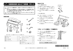
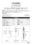
■ 組み立て方法
ピアノ設置業者様用 組み立て説明書
(KR115)
○ピアノの脚を取り付ける
このチラシはピアノ設置業者専用です。お客様はピアノの分解、組み立ておよび移動は行わな
いでください。
分解 / 組み立ておよび移動の際は、必ず、商品をお求めの販売店か、ピアノ運送専門業者にご
相談ください。お客様ご自身の分解 / 組み立ておよび移動により発生した事故、故障に関して、
ローランドは一切の責任を負いかねますので予めご了承ください。
1.
脚 A をピアノ本体の下の位置に持っていきます。
2.
六角レンチ f を使って、ボルト e で脚 A を
ピアノ本体に固定します(2 カ所)
。
3.
同じように残り 2 つの脚 A もピアノ本体に固定し
1
e
ます。
2
e
ピアノとスタンドは大変重いので、運ぶときは必ず 3 人以上で行い、取り扱いには充分ご注意
ください。また、ピアノは水平な場所に設置してください。
○ペダルを取り付ける
4.
ネジ a でペダル B をピアノ本体に固定します
(4 カ所)。
■ 部品の確認
5.
fig.00-01(ピアノの部品の絵)
ネジ b でペダルとペダル支え棒 C を固定します
(1 カ所)。
a
d
A
A
6.
7.
e
b
4
ネジ b でペダル支え棒 C をピアノ本体に固定し
b
ます(1 カ所)
。
5
b
a
6
インシュレーター D をスタンドのキャスターの下
a
7
に敷きます。
B
D
C
A
c
f
ペダル・コードと電源コードを接続する
D
D
D
組み立てる前に、以下の部品がすべてそろっているか確認します。
A
脚(スタンド)
3
a
B
ペダル
1
b
ネジ (M4 x 16)
3
C
ペダル支え棒
1
c
ネジ (4 x 10)
3
D
インシュレーター
3
d
コードクランプ
4
ネジ(M8 x 30)
4
ソケット・スクリュー
(M12 x 75)
e
f
6
スプリング・ワッシャー
6
平ワッシャー
6
六角レンチ
1
1.
電源コードを AC インレットに差し込みます。
2.
ペダル・コードをペダル端子に差し込みます。
3.
図のように電源コードとペダル・コードをまとめて A
A
B
の位置で、コードクランプ d とネジ b を使って
固定します。
4.
C
電源コードとペダル・コードを B、C、D の位置で、
D
コードクランプ d とネジ c を使って固定します。
5.
電源コードをコンセントに差し込みます。
このチラシは、必ず取扱説明書と一緒に保管してください。
*
KR115
© 2005 ローランド株式会社 本書の一部、もしくは全部を無断で複写・転載することを禁じます。
4
0
6
7
2
8
8
9
-
40672889
0
2
*
2PD
Leaflet For a Dealer or a Qualified Professional Installer (KR115)
This leaflet is for a dealer or a qualified professional installer. The customer should not
attempt to assemble the instrument. Please consult your Roland dealer to assemble the
piano. Roland cannot warrant the safety of the assemble operation, if this operation is
carried out by the customer.
As the piano and legs are very heavy, always use three or more people when moving the
piano, and be sure to handle it carefully. Then the piano must be carefully placed so it is level
and sure to remain stable.
■ Assemble Procedure
Attach the legs to the piano
1.
Position the legs A in place beneath the piano.
2.
Use the hex wrench f to fasten the leg A to the
1
piano (at four points) with the bolts e .
3.
■ Check the Parts
Fasten the two other legs A to the piano in the
same fashion.
e
2
e
fig.00-01¬
Attach the lyre assembly
a
d
A
A
4.
Using the screws a , fasten the lyre assembly B
to the piano (at four points).
5.
Using the screws b , fasten the lyre support sticks
e
b
C to the lyre box (at one point).
B
6.
C
Using the screws b , fasten the lyre support sticks
b
C to the piano (at one point).
A
c
f
7.
D
D
4
5
b
a
6
a
Place the caster cups D beneath the casters of the
legs.
7
D
D
Connecting the Pedal Cord and the Power Cord
Before you begin assembling the stand, check that all the following parts were supplied.
A
Legs
3
a
Screws (M8 x 30)
4
B
Lyre assembly
1
b
Screws (M4 x 16)
3
C
Lyre support sticks
1
c
Screw (4 x 10)
3
D
Caster Cups
3
d
Cord Cramp
4
Hex socket head cap bolts
(M12 x 75)
6
Spring washers
6
Plain washers
6
Hex wrench
1
e
f
1.
2.
3.
Connect the supplied power cord to the AC inlet jack.
A
Connect the pedal cord to the Pedal jack.
B
Cramp the power cord and pedal cord with Cord
Cramp d and screw b at A (see the picture above).
4.
Cramp d and screw c at B, C and D (see the
picture above).
5.
C
Cramp the power cord and pedal cord with Cord
D
Plug the power cord into an AC outlet.
Please keep this leaflet together with the Owner’s Manual so that you can quickly refer to it again when necessary.
*
KR115
Copyright © 2005 ROLAND CORPORATION
4
All rights reserved. No part of this publication may be reproduced in any form without the written permission of ROLAND CORPORATION.
0
6
7
2
8
8
9
40672889
-
0
2
*
2PD