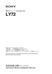
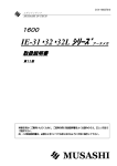
1
User’s Manual
No. 99MAH012B1
SERIES No. 543
ABSOLUTE ID-C112R 演算形デジマチックインジケータ
注記 (b)
はじめに
SR44
SR44
1000
・ スピンドルが基準面と被測定面に対して垂直になるように固定して下さい。軸線(スピンドル)が基準面(測定面)
に垂直でない場合、測定値に誤
差が加算されます。
・ フィクスチャ、治具等に取り付ける際は、φ8G7(+0.005∼+0.02)程度の嵌合部を持つ、すり割り付きのホルダにステムを固定する方法を推奨
します。
[3.5]
(a)
本機は、スピンドルの移動量を x とした演算式 ƒ (x) =Ax+B+Cx-1 を用いて内部演算を行う特殊ゲージです。各種フィクスチャを取付けて、専用アプ
3.5 レバーの取付け
本機はレバー Assy(#902011/別売)
を取付けてご使用頂けます。
レバー Assy には、レバー (a)とストップネジ (b) が同梱されています。
・ キャップを外し、スピンドル上端のネジ(M2.5)を取り外し、ストップネジ (b)を取り付けます。
・ 本機側面のレバー取り付けネジ⑨を緩め、レバー (a)をストップネジ (b) に掛けながら取り付けます。
リケーション(ゲージ)としての使用の他、幅広い用途に応用してご使用いただけます。
ご使用になる前に、この取扱説明書をよくお読み頂き、各機能を十分にご理解の上、正しくお取り扱い下さい。また、本書はお読みになった後も大
切に保管して下さい。本機の仕様、及び本書の内容は将来予告無しに変更することがあります。万一弊社の製造販売に起因する不具合がお買い上げ
SR44
より一年以内に発生した場合、無償修理いたしますので、お求めの販売店、営業所までご連絡下さい。但し、電池等の消耗による故障、又は損傷は
[3.3]
保証の対象外となります。
3.6 測定子の交換
・ 弊社ダイヤルゲージ用オプションの各種替測定子・継足しロッドがご利用頂けます。
・ スピンドルが回らないように、スピンドルをウエス等を介してプライヤで固定し、別のプライヤで測定子を挟んで回し、測定子の取り外し、取り
付けを行って下さい。
電池に関する注意
1
7.6
誤った電池の使い方は、電池の内容物が漏れたり、発熱・破裂の原因となり、思わぬ事故、けがをすることがあります。また、本機の故
障の原因となることもあります。次の事は必ずお守り下さい。
27.6
1
警告
9
3
重要 +0.02
8 +0.005
・ 分解、改造、ショート、充電、100℃以上の加熱、火の中への投入等はしないで下さい。
・ 測定子交換作業の際、スピンドルの固定を行わないと、故障が発生する恐れがあります。また、スピンドルを傷つけてしまうと作動不良が生じ
る恐れがあります。
・ 測定子の変更に伴い、外観寸法、測定力の変化、測定方向の制限等が生じる場合があります。
・ 測定精度に測定子の器差
(フラット測定子の直角度、ローラ測定子の芯振れ等)が累積します。
[3.4]
・ 電池は極性(+と−の向き)に注意して、正しくセットして下さい。
・ 本機で指定されている電池以外は使用しないで下さい。
・ 長期間(3ヶ月以上)ご使用にならない場合は、本体から電池を取り出し、別々に保管して下さい。
・ 電池の破棄、又は保存の際には、絶縁テープで電池の+−極を包むなどの処理をし、電池が他の金属や、電池と接触しないようにして
4. 操作方法
下さい。また、破棄する際は各地方自治体の条例や規制等に従って下さい。
54
60.5
・ 直射日光、高温、高湿の場所を避け、子供の手の届かないところへ保管して下さい。
4.1 概要
・ 本機は、スピンドルの移動量を x とした演算式 ƒ (x) =Ax+B+Cx-1 を用いて内部演算を行う特殊ゲージです。
・ 本機の機能を十分にご使用頂く為には、 (1) 初期設定(4 項目)
、 (2) 機能選択(4 項目)の 2 つの設定が必要となります。また、測定を補助する為
の (3) 測定補助機能(2 項目)があります。
・ 測定までの設定の流れはフローチャート図をご覧下さい。また、各機能の説明項と概要は次の通りです。
[3.6]
・ 取り外した電池は、誤って飲み込むことがないようにして下さい。万一、飲み込んでしまった場合、直ちに医師に相談して下さい。
・ 万一、内容物が目や口に入ったり、皮膚に付着した場合は直ちに水で洗い流し、直ちに医師に相談して下さい。衣服に付着した場合は
水で洗い流して下さい。
(1) 初期設定
・ 4.2 最小表示量と演算係数の設定 : 最小表示量と、演算式 ƒ (x) =Ax+B+Cx-1 の係数(A,B,C)を設定します。
本機は、設定された係数による演算式の結果を表示します。本設定を行うと、プリセット値、公差値がク
リアされます。
・ 4.3 オリジンポイントの設定
: 内部演算を行う為の、オリジンポイント(演算基準位置)を設定します。
オリジンポイントは演算式 ƒ (x) =Ax+B+Cx-1 の変数 x=0 となる位置です。設定した演算計数によっては、
オリジンポイントの設定を適切に行わないと正しい値を表示しない場合があります。
・ 4.4 プリセット値の設定
: プリセットはマスタ合せを行う時に使用します。
最小表示量、又は演算係数が変更された場合、プリセット値はクリアされます。必要に応じて再設定を
行って下さい。
・ 4.5 プリセット値の呼び出し
:「4.4 プリセット値の設定」で設定されたプリセット値を呼び出します。
廃棄に関する注意
・ 本機には液晶、及び酸化銀電池が使用されています。それぞれの廃棄にあたっては、各地方自治体の条例や規制等に従って下さい。
2
4
・ 液晶の内部には、刺激性物質が含まれています。万一、液状の内容物が誤って目や皮膚等に付着した場合、清浄な流水で洗浄して下
10
さい。口に入った場合は、直ちに口内を洗浄し、大量の水を飲んで吐き出した後、医師に相談して下さい。
警告
5
4
ご使用上の注意事項
以下の行為・状況は、本機の故障・誤動作の原因となりますので、お気をつけ下さい。
6
[4.1]
重要 ・ 分解、改造を行わないで下さい。
10.5
・ 尖ったもの(ドライバー、ボールペンの先等)でキーを操作しないで下さい。
電池セット
(交換)
・ お手入れの際は、希釈した中性洗剤に浸した柔らかい布をご使用下さい。有機溶剤(シンナー、ベンジン)をご使用になると、変形や故障の原
オリジンポイントの設定
・ スピンドルの汚れは動作不良の原因となります。アルコールを含ませた布等で汚れをきれいに拭き取りご使用下さい。
8
注記 49.6
7
4.2
4.3
4.4
4.5
1. 各部名称・寸法
寸法値は mm を示します。
②平裏蓋
⑦電池キャップ ⑧ LCD ④ステム
⑨レバー取付ネジ
⑩レリーズ取付穴
⑤スピンドル
46.5
キー名称
電源の ON/OFF
mm ⇔無単位表示切換
⑬ TOL.
<2sec
>2sec
<2sec
ゼロセット
ABS 系への切換
公差設定・公差判定解除
⑭ PRESET/SET
通常モード
プリセット(絶対原点位置を設定)
<2sec
ピークホールドの解除
データ出力(データ処理装置接続時)
7.3
21.2
⑫ ZERO/ABS
M2.5×0.45
0
8 –0.009
⑮ DATA/HOLD
2
⑯ MODE
<2sec
>2sec
>2sec
+[PRESET/SET]
データホールド(データ処理装置未接続時)
ファンクションロック⇔解除
測定モード切換
最小表示量・演算係数設定
+[ZERO/ABS]
オリジンポイントの設定(演算基準位置の設定)
注記
4.6
4.7
4.8
4.9
操作方法
―
測定(電源ON)
4.6 ABS 系と INC 系
4.11 データ出力 / データホールド
[4.2]
4.10 ファンクションロック
4.8 測定モード切換
4.2 最小表示量と演算係数の設定
MODE
4.3 オリジンポイントの設定
短く押す
(2sec未満)
測定補助機能
SET
SET
4)
Ax+B+Cx–1
10)
Ax+B+Cx–1
Ax+B+Cx–1
mm
mm
SET
SET
・ 本機は、酸化銀電池(SR44)1個を、+端子面を上に向けてセットします。
2)
5)
mm
11)
mm
mm
SET
2) シールがはみ出ない様に気を付け、電池キャップを時計方向に回して取付けます。
3) 電池をセットし直すと、 [3.1-b] に示す表示になります。 [MODE] キーを押しながら、 [ZERO/ABS] キーを押し、計数状態(通常モード)にして
7)
下さい。
Ax+B+Cx–1
A
mm
mm
注記 12
B
A
Ax+B+Cx–1
SET
SET
・ お買い上げ時は、本機に電池はセットされておりません。電池をセットしてから、お使い下さい。
[3.1-a]
[3.1]
[3.2]
[3.2] 330°
12)
mm
SET
オリジンポイントの設定を再度行って下さい。
(A)
Ax+B+Cx–1
A
・ お買い上げ時に付属されている電池は、機能や性能を確認するためのものです。所定の寿命がもたない場合がありますので、ご了承下さい。
・ 電池交換直後のオリジンポイントの設定は、適切な位置で行う必要は有りません。但し、適切な位置で設定が行われなかった場合、必要に応じ、
13
3.2 表示部の角度調整
mm
SET
A
–1
Ax+B+Cx
表示部は、初期位置(A)から時計回りに 330°(B)まで回転します。
mm
重要 mm
SET
・ A,B にストッパが入っていますので、これを超えて回転させないで下さい。故障の原因となります。
(B)
・ 表示部を引き抜いたり、押しこんだりしないで下さい。故障の原因となります。
Ax+B+Cx–1
3.3 レリーズの取付け
本機は、レリーズ(#540774/ 別売)を取付けてご使用頂けます。
mm
・ レリーズ穴のネジ !0(M2.6)を #0 の十字ドライバで外し、レリーズを穴の奥までしっかりねじ込みます。
重要 最小表示量一覧
・ レリーズを強く引張ったり、叩いたりするとネジ山が欠落することがあります。
・ レリーズ以外のものを差し込んだり、過剰に力がかかると故障する恐れがあります。
・ レリーズが緩んだ状態でスピンドルを上下させると、内部部品を損傷させる恐れがあります。
[3.1-b]
q
0.0002
u
0.02
w
0.0005
i
0.05
3.4 スタンド・治具への取付け
e
0.001
o
0.1
本機はスタンド、又は各種フィクスチャ等に固定、もしくは取り付けてお使い下さい。
r
0.002
!00
0.2
t
0.005
!1
0.5
y
0.01
!2
1
重要 止めネジ等でステムを直接締め付けて固定する方法はできるだけ避けて下さい。300N・cm 以上の締め付けトルクで固定した場合、作動不良が生じ
る恐れがあります。
長く押す
(4sec)
● 最小表示量の設定
1) [MODE]キーを押しながら、2 秒以内に[SET]キーを短く押します。最小表示量設定モードとなり、表示の左上に“Ax + B + Cx-1”が点灯表示さ
れ、前回設定した最小表示量を点滅表示します。
2) [SET]キーを長く押す事で最小表示量(12段階/別表参照)は順に切換ります。希望の最小表示量になるまで、
[SET]キーを長く押し続けて下さい。
3) 希望の最小表示量の数値に切換わったら一旦離し、
[SET]キーを短く押し、最小表示量の設定を終了させ、演算係数の設定を行います。
SET
1)
SET
長く押す
(2sec以上)
4.2 最小表示量と演算係数の設定
・ 本機はスピンドルの移動量を x とした演算式 ƒ (x) =Ax + B + Cx-1 を用いて内部演算を行う特殊ゲージです。演算式の各項の係数 A、B、C は自由
に設定することができます。また、演算結果の表示値の最小表示量は 12 段階の切り換えが可能です。
・ 最小表示量、及び演算係数の設定は通常モード時のみ設定可能です。
・ 本設定を変更した場合、プリセット値、公差値は全てクリアされます。必要に応じて再設定を行って下さい。
[例] mm 単位系において、最小表示量を 0.01 に、各係数を A=2.5000、B=0.5000、C=0.0 に設定する場合
電源OFF
1) 電池キャップの溝に硬貨等を当て、反時計方向(矢印の方向)に回して外し、新しい電池と交換します。
3
以降の説明図では、キーの押し方を次の 3 通りに区別します。
3.1 電池の交換
11
14
活用下さい。
4.10 ファンクションロック
4.11 データ出力/データホールド
4.7 公差値の設定
4.4 プリセット値の設定
4.5 プリセット値の呼び出し
―
mm
15
演算係数、オリジン設定位置、プリセット位置の初期設定に関する値を、代表アプリケーション別に一例を別紙(付録)に示します。参照の上、ご
ABS系とINC系
公差値の設定
測定モード切換
単位系の切換
4.9 単位系の切換
3. セットアップ
16
(3) 測定補助機能
・ 4.10 ファンクションロック
: 誤操作を防止する為に、キー操作の制限を行います。
・ 4.11 データ出力 / データホールド : データの外部出力、又はデータの表示ホールドを行います。
機能選択
機能の説明
<2sec
>4sec
⑪ ON/OFF
測定子結合部ねじ
条件
最小表示量と演算係数の設定
オリジンポイントの設定
プリセット値の設定
プリセット値の呼び出し
⑥測定子 2. スイッチの名称と機能
16.5
54.4
③出力コネクタ(ゴムキャップ付)
: 絶対測定用の ABS 測定系と比較測定用の INC 測定系を選択します。
: 公差判定を行うための上下限値の設定・確認と公差判定表示への切換を行います。
最小表示量、又は演算係数が変更された場合、公差値はクリアされます。 必要に応じて再設定を行って下さい。
: 通常測定モード、最大値 (Max.) ホールドモード、最小値 (Min.) ホールドモードの切換を行います。
: 単位系の切換を行います。
・ 4.8 測定モード切換
・ 4.9 単位系の切換
初期設定
本機、及び測定の対象は、十分温度に慣らしてから測定を開始し、できる限り温度変動の少ないところでご使用下さい。
①キャップ
(2) 機能選択
・ 4.6ABS 系と INC 系
・ 4.7 公差値の設定
測定フローチャート
因となります。
● 演算係数(A・B・C)の設定
4) 演算係数の設定モードになると、表示左上に点灯表示されていた“Ax + B + Cx-1”の中の“A”のみが点滅表示され、前回設定した係数 A の値
を表示します。
5) [SET]キーを長く押すと置数桁を順に移動できます。
6) 置数したい桁が点滅表示を開始するまで[SET]キーを押し続け、置数する桁が点滅表示を開始した時に[SET]キーを一旦離します。
7) 希望の数字が表示されるまで、
[SET]キーを繰返し短く押します。
8) 符号は+→−、数字は 0 → 1 → 2 →…→ 9 の順に切換ります。
9) 手順 6)、7)を繰返し、他の桁も同様に設定します。
10) 係数 A の設定中は、表示左上に“A”のみ点灯表示されます。設定後、
“A”が点滅表示されている状態にし、
[SET]キーを短く押すと、表示左上
では“B”が点滅表示され、前回の係数 B の設定値が表示されます。
11) 係数 A と同様に係数 B の設定を行い、更に係数 C の設定も同様に行います。
12) 係数 C の設定後、
“C”が点滅表示されている状態にし、
[SET]キーを短く押すと、新しい演算係数による測定値が表示されます。また、演算係数
が A=1、B=C=0 以外に設定された場合、表示の左上に“Ax + B + Cx-1”が常時点灯表示されます。
重要 ・ 設定した値は、電池の交換、及び電源を OFF にしても保持されます。
・ 最小表示量、及び係数設定中に電源を OFF し、再度 ON した場合、設定中の値が取り消され、設定開始前の状態へ戻ります。
・ 本設定は、INC 測定、公差判定測定、ピーク(ホールド)測定が解除されていない場合、設定を行うことができません。
・ 設定終了後、表示される値はオリジンポイントにより変わるため、必ず図と同じ値が表示されるとは限りません。
・ 演算処理の結果、オーバーフローとなることがあります。
・ 本機のスピンドル位置の分解能( x の検出分解能)は 0.001mm です。本機は、この x の値を元に演算を行いますので、設定された最小表示量と
演算係数の組合わせによっては、末桁が変化しない場合、または表示値が全く変化しない場合があります。
例〉 末桁が変化しない
: 最小表示量 =0.0002mm、演算係数 A=1、B=C=0 に設定
表示値が全く変化しない : 演算係数 A=C=0 に設定
適切な組み合わせとなる様、最小表示量と演算係数の設定を行って下さい。
・ 最小表示量、及び演算係数のお買い上げ時の設定は、最小表示量:0.001mm / 演算係数: A=1、B=C=0 となっています。
・ 各係数の設定可能桁数は以下のようになっています。
係数
設定可能桁数
A
B
C
小数点以上 2 桁、小数点以下 4 桁
小数点以上 2 桁、小数点以下 4 桁
小数点以上 5 桁、小数点以下 1 桁
・ 置数設定時、[DATA/HOLD]キーを押しながら[SET]キーを操作すると、桁の移動、及び数字の切換りが、逆の順で行えます。また、[MODE]キーを
押すと、変更された置数はそのままの状態で、桁移動前の状態へ戻ります。
・ 本設定において設定値を変更した場合、プリセット、及び公差は設定した値も含めて全てクリアされます。何も値を変更しなかった場合は全て
元の状態が保持されます。また、オリジンポイントの設定はクリアされません。
・ 本設定のみ外部入力による設定を行うことができます。詳細に付きましては、弊社営業所、又は代理店へお問合せ下さい。
– – – – – – – – – – – – – – – – – – – – – – – – – – – – – – – – – – – – – – – – – – – – – – – – – – – – – – – – – – – – – – – – – – – – – – – – – – – – – – – – – – – – – – – – – – –– – – – – – – – – – – – – – – – – – – – – – – – – – – – – – – – – – – – – – – – – – – – – – – – – – – – – – – – – – – – – – – – – – – – – – – – – – – – – – – – – – – – – – – – – – –
User’s Manual
No. 99MAH012B1
SERIES No. 543
ABSOLUTE ID-C112R Calculation type Digimatic Indicator
NOTE
• Set up the instrument with the spindle perpendicular to the reference plane or the measured surface. If the spindle axis is not perpendicular
to the reference plane (measured surface), measurement errors will result.
• If the instrument is to be secured with a fixture, fix it by the stem in a slotted hole of approx. φ8G7 (+0.005 to +0.02) or φ9.52 (+0.005 to
+0.02).
[3.5]
(b)
(a)
Introduction
SR44
SR44
1000
SR44
This indicator is a special gage that performs internal calculation using formula ƒ (x) =Ax+B+Cx-1, assuming a spindle displacement as x. This
indicator is used for wide-purpose applications by mounting a variety of fixtures in addition to usage as a dedicated application gage.
To obtain the highest performance from this instrument and to use it safely, read this User's Manual prior to use.
After reading, retain this manual for future reference. Specifications of this instrument and information in this manual are subjected to change
without notice. In the event that the instrument should prove defective in workmanship or material, within one year from the date of original
purchase for use, it will be repaired or replaced, at our option, free of charge upon its prepaid return to us. Please contact Mitutoyo office.
However, the warranty shall not apply if the product fails or is damaged as a result of fair wear and tear including battery drain.
3.5 Mounting of Lifting Lever
This instrument can be used with the optional lever Assy (#902011) (ISO) or (#902794) (AGD) attached into the lever mounting tapped hole.
The lever Assy is packed along with the lever (a) and the stopper screw (b).
• Demount the cap, unscrew the screw (M2.5) (ISO) or #4-48UNF(AGD) at the top of the spindle, then mount the stop screw (b) instead.
• Loosen the lever mount screw (9), and mount the lever (a) while hanging it on the stop screw (b).
3.6 Replacement of Contact Point
• Various type of contact points and extension rods optionally available.
• Hold the spindle with pliers protecting it with rags, hold the contact point with another pliers, and turn to remove or mount it.
IMPORTANT
• Use a rag to protect the spindle during the above work to avoid instrument failure. The spindle does not move smoothly if damaged.
• Different contact point results in different external dimensions, measuring force, and imitation of measuring direction.
• Contact point error such as perpendicularity of a flat contact point, run-out of roller point, etc. adds to the measurement error.
[3.3]
Warning on Battery
1
7.6
7.6
.3″
27.6
1.09″
27.6
(1)
(9)
+0.02
8(9.52) +0.005
4. Operation Procedure
[3.4]
• Always use the recommended battery.
• If the instrument is not used for more than three months, remove the battery from the instrument to store it separately.
• For disposing or storing battery, cover the positive (+) and negative (–) terminals with a piece of insulating tape to prevent contact
with other metals. When disposing it, follow the local ordinances or regulations of respective local governments.
• Keep batteries avoid direct sunlight, high temperature, high humidity and out of the reach of children.
• When the battery is removed, do not swallow it by mistake. In case a cell or the battery has been swallowed, consult a physician
immediately.
• Should the content accidentally come into contact with the eye or skin, or get into the mouth, rinse with water immediately and
consult a physician. Should it attach to the cloths, wash it with water.
54
2.13″
60.5
2 3/8″
60.5
(3)
54
If the battery is misused or abused, leakage or, in extreme cases, explosion and/or fire can result. Observe the following precautions to avoid instrument failure and malfunction.
• Do not disassemble, deform, short-circuit, charge, heat the battery to 100°C and over, or throw the battery into fire.
WARNING • Always insert batteries correctly with regard to polarity (+ and –) marked on the battery and the equipment.
[3.6]
Warnings on Disposal
(2)
(4)
• For this instrument the LCD and a silver oxide battery are used. When disposing them, follow the local ordinances or regulations
of respective local governments.
• The LCD part contains irritating substance. Should the liquid content accidentally come into contact with the eye or skin, rinse
with water immediately and consult a physician. Should it get into the mouth, immediately rinse inside the mouth, swallow plenty
WARNING
of water, vomit, then consult a physician.
(10)
(5)
(6)
4
Precaution on Use
Observe the following precautions to avoid instrument failure and malfunction:
IMPORTANT
• Do not disassemble and modify this instrument.
• Do not press the key with a pointed object, such as a screwdriver or ball-point pen.
• To clean the instrument, use a soft cloth soaked in a diluted neutral detergent. Do not use any organic solvent (thinner or benzene). It may
deform or damage the instrument.
• The contaminated spindle may cause malfunction. Wipe them off with a cloth damped with alcohol.
10.5
13/32″
49.6
1.95″
(7) (8)
[4.1]
Battery Replacement
Measuring Flowchart
Setting the Origin Point
NOTE
Use the instrument in a temperature-controlled room that has minimum temperature fluctuation. Allow a sufficient time for both the instrument
and workpiece to thermally stabilize before performing measurement.
Initial Setup
4.2 Setting the Resolution and Arithmetic
Coefficient
4.3 Setting the Origin Point
4.4 Setting the Preset Value
4.5 Calling the Preset Value
44.2
17.4″
16.5
14.2
9/16″
54.4
50.95
2″
46.5
1. Dimensions and Nomenclature
• Dimensions without unit are in mm.
is the symbol for American Gage Design (AGD) representing the dimensioning meets the ANSI standard for AGD Group 2 indicator.
•
(Applicable to the model with suffix E.)
(1) Cap (2) Flat back (3) Output connector (with a rubber cap) (4) Stem (5) Spindle (6) Contact point (7) Battery cap (8) LCD
(9) Lever mounting screw (10) Release hole
21.2
20.05
.79″
2. Switches and Functions
Switch
Condition
6.35
1/4″
7.3
<2sec
M2.5×0.45 thread
0
8 –0.009
No.4-48 thread
0
9.52 –0.03
3/8″DIA
ISO/JIS type
(11) ON/OFF
(in/mm)
AGD type
(12) ZERO/ABS
(13) TOL.
2
(14) PRESET/SET
mm ⇔ Switching to no-unit display
>2sec
Switching inch/metric conversion
(Applicable to the model with suffix M and E)
>6sec
inch/mm ⇒ Switching to no-unit display
(Applicable to the model with suffix M and E)
<2sec
(16) MODE
4.10 Function Lock (key lock function)
4.11 Data output/Data hold
Zero set
4.6 ABS System and INC System
Switching into ABS system
4.7 Setting the Tolerance
Presetting
4.4 Setting the Preset Value
4.5 Calling the Preset Value
Releasing the peak hold
Function lock ⇔ Release
[4.2]
MODE
—
Data output (When the data processing unit is connected)
Data hold (When the data processing unit is disconnected)
>2sec
Measurement Sub-functions
Power OFF
Torelance setup/tolerance judgment release
<2sec
Measurement
(Power on)
4.9 Switching the Unit System
>2sec
(15) DATA/HOLD
(11)
—
<2sec
Normal mode
4.11 Data output / Data hold
SET
SET
4)
Ax+B+Cx–1
(12)
(14)
(13)
3
[3.1-a]
(A)
[3.2]
330°
[3.1-b]
Ax+B+Cx–1
mm
mm
SET
mm
SET
SET
4.10 Function Lock (key lock function)
>2sec
Switching the measuring mode
+[PRESET/SET]
Resolution/arithmetic coefficient setup
4.2 Setting the Resolution and Arithmetic Coefficient
+[ZERO/ABS]
Origin point setup (calculation reference position setup)
4.3 Setting the Origin Point
Ax+B+Cx–1
4.8 Switching the Mode
mm
5)
3.4 Securing the Instrument
Use this instrument with it secured or mounted onto the stand or either of various fixtures.
IMPORTANT
• Avoid fixing the stem directly using a lock screw. If fixed under a clamping torque of 300N•cm or more, the spindle may not move smoothly.
11)
mm
mm
SET
7)
3.1 Battery Replacement
Set a silver oxide battery (SR-44) with the positive (+) side facing front.
1) Remove the battery cap by turning it counterclockwise (arrow direction) with a coin set in the groove. Then replace the battery by new one.
2) Secure the battery cap by turning it clockwise. Be careful not to allow the seal to protrude.
3) Immediately after the battery is set (or replaced), the indicator displays the message as shown in the figure [3.1-b]. The indicator enters the
count mode (Normal mode), hold down [MODE] key , then press [ZERO/ABS] key shortly at once.
NOTE
• The supplied battery is separately packed for shipping. Load the battery before using the Digimatic indicator.
• The supplied battery is just to check the function and performance. The specified battery life may not be assured. Care should be taken.
• Immediately after replacing the battery, the origin point does not need to be set at an appropriate position of the spindle. However, if the
origin point was not set at an appropriate spindle position, reset the origin point as required.
3.3 Mounting of Release
This instrument can be used with the optional release (#540774) attached into the release hole.
• Remove screw (10) (M2.6) of the release hole with #0 Phillips screwdriver and be sure to screw the release in.
IMPORTANT
• Jerking or knocking the release may cause the thread to be chipped off.
• Do not insert other than the release to the hole or apply excessive force. Caution, risk of instrument failure.
• If the spindle is displaced upward and downward with the release being loosened, there may be a possibility of damage to internal parts.
B
A
2)
Ax+B+Cx–1
A
mm
mm
SET
SET
Ax+B+Cx–1
A
12)
mm
SET
mm
SET
A
Ax+B+Cx–1
mm
mm
SET
3.2 Adjustment of Display Unit Angle
The display unit rotates 330° (B) clockwise from the initial position (A).
IMPORTANT
• Do not rotate the display unit beyond the stoppers at positions A and B. Caution, risk of instrument failure.
• Do not pull or push the display unit. Caution, risk of instrument failure.
(B)
SET
10)
Ax+B+Cx–1
1)
3. Setup
(15)
ABS and INC system
Setting the Tolerance
Switching the Mode
Switching the Unit System
Operation procedure
Turning the Power ON/OFF
>4sec
<2sec
(16)
Function
Three ways of processing key are used in the following illustration.
Function Selection
4.6
4.7
4.8
4.9
4.1 Outline
• This indicator is a special gage that performs internal calculation using formula ƒ (x) =Ax+B+Cx-1, assuming a spindle displacement as x.
• To make the most of the dial indicator functions, it is necessary to perform two setups: (1) Initial setup (4 items) and (2) Function selection
(4 items). The indicator also provides (3) Measurement Sub-functions (2 items).
• See the flow chart to the left for the setting flow up to measurement. The reference sections and outlines are described below.
(1) Initial setup
• 4.2 Setting the Resolution and
: Set the resolution and coefficients (A, B, and C) in formula ƒ (x) =Ax+B+Cx-1.
Arithmetic Coefficient
This indicator displays the calculation result of the formula using the set coefficients. The preset
value and tolerances are cleared, if the resolution or coefficient settings are changed.
• 4.3 Setting the Origin Point
: Set the origin point (calculation reference point) for calculation.
The origin point is the spindle position at which variable x in formula ƒ (x) =Ax+B+Cx-1 becomes 0.
If the origin point is not properly set, a correct value may not be displayed depending on the set
arithmetic coefficients.
• 4.4 Setting the Preset value
: Preset uses mastering.
If the resolution or arithmetic coefficients settings are changed, the preset value is cleared. Set a
preset value again if necessary.
• 4.5 Calling the the Preset Value : Call the preset value that has been set according to “4.4 Setting of Preset value”.
(2) Function selection
• 4.6 ABS System and INC System : Select the ABS system for absolute measurement or the INC system for comparative measurement.
• 4.7 Setting the Tolerance
: Check and set the upper/lower limit for tolerance judgment and switching to the tolerance judgment. The tolerances are cleared, if the resolution or coefficient settings are changed. Set tolerances again if necessary.
• 4.8 Switching the Modes
: Switching 3 measurement modes to either “Normal mode”, “Maximum (Max.) Hold mode”, or
“Minimum (Min.) Hold mode”.
• 4.9 Switching the Unit System
: Select the unit systems.
(3) Measurement Sub-functions
• 4.10 Function Lock
: Restrict key operations to prevent miss operation.
• 4.11 Data output/Data hold
: Perform data output to data processor or holding the data.
NOTE
As measurement examples of typical applications, the arithmetic coefficients, origin setup position, and preset position are shown in another
sheet (Appendix). Make the most of those examples.
Ax+B+Cx–1
mm
Press shortly (under 2 sec)
Press and hold (2 sec or more)
Press and hold (4 sec or, 6 sec or more)
4.2 Setting the Resolution and Arithmetic Coefficient
• This indicator is a special gage that performs internal calculation using formula ƒ (x) =Ax+B+Cx-1, assuming a spindle displacement as x.
Any numeric value can be set for coefficients A, B, and C of each term in the formula. Also, it is possible to switch the resolution of calculated
result display values to either of 12 stepped resolutions.
• The resolution and arithmetic coefficients can be set only in the Normal mode.
• The preset value and tolerances are cleared, if the resolution and coefficient setting are changed. Set tolerances again if necessary.
[Example] (In mm system) When setting the resolution to 0.01, and coefficients A, B, and C to 2.5000, 0.5000, and 0.0, respectively:
• Setting the Resolution
1) Hold down [MODE] key, then press [SET] key shortly at once (under 2 sec). The instrument enters the Resolution Setup mode, then
displays “Ax+B+Cx-1” at the upper left corner of the LCD and blinks the most recently set resolution.
2) Hold down the [SET] key, then the resolution (12-step/See the separate table) will change sequentially. Hold down the [SET] key until the
desired resolution is displayed.
3) When the resolution is changed to the desired value, release the [SET] key once, then press the [SET] key shortly to complete the
resolution setup. Next, set the arithmetic coefficients.
• Setting the arithmetic coefficients (A, B, and C)
4) When the instrument enters the arithmetic coefficient setup mode, only “A” of “Ax+B+Cx-1” displayed at the upper left corner of the LCD
blinks and the most recently set value of coefficient A is displayed.
5) Hold down the [SET] key, then the numeric entry digit of the coefficients will change sequentially.
6) Hold down the [SET] key until the desired coefficient digit blinks. When the desired coefficient digit starts blinking, release the [SET] key
once to enter a numeric value.
7) Repeat pressing the [SET] key shortly until the desired numeric value is displayed.
8) The sign changes in the order of + to –, and the numeric value changes in the order of 0, 1, 2, - - -, 9, and 0.
9) Repeat steps 6) and 7), and set coefficients at other digits in the same way.
10) During setup of coefficient A, only the “A” digit lights up at the upper left corner of the LCD. While “A” is blinking after the setup, press the
[SET] key shortly, then the “B” digit starts blinking at the upper left corner and the most recently set value of coefficient B is displayed.
11) In the same way used for coefficient A, set coefficient B and then coefficient C.
12) While “C” is blinking after the coefficient C setup, press the [SET] key shortly. The measurement value using the new coefficients is
displayed. Also, if the arithmetic coefficients are set to other than A=1, B=C=0, "Ax+B+Cx-1" is displayed with it kept lit at the upper left
corner on the LCD.
IMPORTANT
• Set value will be retained if the battery is replaced and the power OFF.
• If the power is turned OFF then ON during the resolution and arithmetic coefficients setting, the set value is cleared and it restores the state
before setting.
• These setup procedures cannot be performed unless the INC measurement, Tolerance judgment or Peak (hold) measurement is released.
• Since the measurement value displayed after completing the setup varies depending on the origin point, the instrument will not always
display the same value as shown in the figure.
• As the result of calculation processing an overflow error may result.
• This indicator's sensor resolution (x resolution) is 0.001mm (=0.00005 in). As it calculates using this resolution, the end digit may not
change depending on the combination of defined resolution and arithmetic coefficient.
[Ex.] End digit is not counting case
: Resolution = 0.0002mm, Coefficient A=1, B=C=0
The display value is not change case : Coefficient A=C=0
Set the resolution and arithmetic coefficients, in order to have the appropriated combination.
• The resolution and arithmetic coefficients have been factory set to 0.001mm (or 0.00005″) and A=1, B=C=0, respectively.
• The number of digits that can be set for each coefficient is shown in the following table.
List of resolution
mm system
no-unit system
inch system
(1)
0.0002
0.00001
(2)
0.0005
0.00002
mm system
no-unit system
inch system
(7)
0.02
0.001
(8)
0.05
0.002
(3)
0.001
0.00005
(9)
0.1
0.005
(4)
0.002
0.0001
(10)
0.2
0.01
(5)
0.005
0.0002
(11)
0.5
0.02
(6)
0.01
0.0005
(12)
1
0.05
Coefficient
A
B
C
mm unit system/no-unit display system
inch unit system (unique to mm/inch model)
2 digits of intergers, 4 digits of decimals
2 digits of intergers, 4 digits of decimals
1 digit of intergers, 5 digits of decimals
5 digits of intergers, 1 digit of decimals
2 digits of intergers, 4 digits of decimals
• If the [SET] key is pressed while holding down the [DATA/HOLD] key at the numeric entry time, the moving direction of blinking digit and the
sequence of changing numbers will be reversed. Also, press the [MODE] key to return to the status before moving the numeric entry digit
with the changed entry number left as it is.
• If any setting is changed in this coefficient setup, all existing values including the preset value and tolerances are cleared. If none of the
settings is changed, all existing values are retained.
The origin point setting will not be changed.
• This setup can only be performed by external numeric entry. For detailed information, contact Mitutoyo sales office or your dealer.
[4.3]
Ax+B+Cx–1
1)
Ax+B+Cx–1
2)
c
4.3 オリジンポイントの設定
・ 内部演算を行うための、オリジンポイント(演算基準位置)の設定を行います。
・ オリジンポイントは演算式 ƒ (x) =Ax+B + Cx-1 の変数 x=0 となる位置です。設定した演算係数によっては、オリジンポイントの設定を適切に行わ
ないと正しい値を表示しない場合があります。
・ オリジンポイントの設定により、プリセットはクリアされます。但し、設定した値はメモリされていますので、必要に応じて再度プリセット値を
呼び出して下さい。
・ オリジンポイントの設定は通常モードのみ可能です。
1) 適切なスピンドル位置(オリジンポイントとする位置)で、[MODE]キーを押しながら、2 秒以内に[ZERO/ABS]キーを短く押して下さい。キー操
作を行った位置でオリジンポイントは設定されます。
2) オリジンポイントが設定された直後に表示される値は、x=0の時の演算結果となります。
3) 電池セット(交換)直後は、図のような表示になります。オリジンポイントの設定を行い、通常モードにして下さい。
mm
MODE ZERO/ABS
mm
*この時表示される値は、x=0
の時の演算結果です。
3)
10.000
上限値 8.000
a
5.000
d
下限値
0
–3.000
–5.000
0.000
b
[4.9]
[4.10]
[4.4]
電池交換後、ホールドモードは解除されます。
・ 本機は内部演算を行う際、オリジンポイントを基準(x=0)としたスピンドル移動量を変数 x として演算を行います。各種フィクスチャ、治具等に
合ったオリジンポイントが設定されなかった場合、正しい演算結果を表示出来ない場合があります。
・ 設定されたオリジンポイントは電源を OFF にしても保持されます。但し、電池交換を行った場合、再度オリジンポイントの設定を必要とします。
・ オリジンポイントの設定を行った後は、プリセットは解除されます。但し、設定した値は保持されていますので、再度値を呼び出して下さい。
[4.5]
PRESET
PRESET
1)
mm
PRESET
基準ゲージ
2)
mm
mm
PRESET
P
3)
mm
mm
PRESET
・
・
・
・
mm
[4.7]
12,000
TOL.
があります。ピークホールドモード測定時において、本機をワークから移動(スピンドルを移動)する際は、ピークホールド後に [HOLD]キーを
<本機>
mm
設定した値は、電池の交換、及び電源を OFF にしても保持されます。
プリセット設定中に電源を OFF し、再度 ON した場合、設定中の値が取り消され、設定開始前の状態へ戻ります。
設定されたプリセット値は、最小表示量、及び演算係数の変更を行った際、全てクリアされます。
誤って、プリセットを操作してしまった場合、必要に応じて、オリジンポイントの設定、又はプリセット設定を行って下さい。
4.5
1)
2)
3)
2)
mm
GND
–
2. *1 DATA
O
3. *1
CK
O
4. *1
RD
O
5. *2
REQ
I
3)
TOL.
4)
重要
mm
4.7 公差値の設定
・ 公差判定の上下限値を確認・設定します。
・ 上下限値は、ABS 系と INC 系に各々別に設定することができます。
・ 上下限値は、各測定モード毎別々に設定することはできません。
[例] 上限値を 10.200mm、下限値を 9.800mm に設定する場合
mm
TOL.
0.2 b*
mm
重要 a*
・ 設定した値は、電池の交換、及び電源を OFF にしても保持されます。しかし、公差判定表示は電池交換後解除されます。
・ 公差設定中に電源を OFF し、再度 ON した場合、設定中の値が取り消され、設定開始前の状態へ戻ります。
・ 設定された公差値は、最小表示量、及び演算係数の変更を行った際、クリアされます。
c* –0.2
10
a*
10.2
9.8
b*
c*
0
(ii)
各モードにて、
[TOL.]キーを短く押すと、“ ”が点滅表示され、前回設定した上限値を表示します。
演算係数設定時と同様に、
[TOL.]キーを操作し、上限値を設定して下さい。
[TOL.]キーを短く押すと、“ ”が点滅表示され、前回設定した下限値が表示されます。
上限値設定後、
“ ”が点滅表示されている状態にし、
上限値と同様に下限値を設定して下さい。
下限値設定後、
“ ”が点滅表示されている状態にします。
上下限値が正しく設定されていることを確認し、
[TOL.]キーを短く押すと公差設定を完了し、公差判定表示になります。この時、上限値<下限
値であった場合、公差エラー表示“E--SE”を表示しますので、[TOL.]キーを短く押し、2)から操作をやり直して下さい。
7) 公差判定時に[TOL.]キーを押すと、公差判定表示は解除されます。
1)
2)
3)
4)
5)
6)
6)
注記 a*:基準ゲージ
b*:上限値
c*:下限値
・ ABS 系・INC 系での上下限値の違い
i) ABS 系での公差設定値
ABS 系での公差設定値は、基準となるゲージの寸法をプリセット値とし、許容範囲内を絶対寸法で設定して下さい。
上限値=基準値+上限の許容値 / 下限値=基準値−下限の許容値
[例] 基準ゲージ寸法= 10.000mm、基準値に対する許容値=± 0.200mm の時の上下限値の設定。
上限値= 10.000 + 0.200 = 10.200(mm) / 下限値= 10.000 − 0.200 = 9.8000(mm)
ii) INC 系での公差設定値
INC 系での公差設定値は、基準となるゲージの寸法を 0 とした許容値として下さい。
[例] 上限値 0.200(mm) 下限値= -0.200(mm)
・ [DATA/HOLD]キーを押しながら[TOL.]キーを操作することで、係数設定時と同様に、桁移動、及び数値切換りの順を逆にできます。また、[MODE]
キーを押すと、変更された置数はそのままの状態で、桁移動前の状態へ戻ります。
[4.8.2]
mm
MODE
Max
mm
1)
MODE
mm
スピンドル移動
Max
4.8 測定モード切換
・ 本機には、3 つの測定モードがあります。
・ 各モードは、[MODE]キーを長く押すことで、
「通常モード」→「最大値(Max.)ホールドモード」→「最小値
(Min.)ホールドモード」→「通常モー
ド」の順で切換ります。
・ 各モードでは、設定された公差にて公差判定を行うことができます。
Max
mm
2)
MODE
mm
SET
Min
mm
mm
● 各測定モードにおける公差判定
・ 通常モード
: 現在値に対する公差判定を行います。
・ 最大値 (Max.) ホールドモード : Max. 値に対する公差判定を行います。
・ 最小値 (Min.) ホールドモード
: Min. 値に対する公差判定を行います。
mm
4.8.1 通常モード
・ 通常の測定を行います。
・ 本機は、電池セット(交換)直後に通常モードに設定されます。
・ 最小値(Min.)ホールドモードにおいて、[MODE]キーを長く押して下さい。通常モードとなります。
Max
3)
MODE
1.5V
*2
100kΩ
10kΩ
CMOS
d3
TOL. TOL.
Max
4)
スピンドル移動
Tr
REQ
5)
mm
d5
d6 d7
MSD
d8
符号
+ : 0(0000)
− : 8(0001)
d9
NPNオープンコレクタ
Nchオープンドレイン
単位
0(0000)mm
1(1000)inch
測定値
RD
REQ
8 < T1 < 25ms
150 < T2 < 180µs
180 < T3 < 500µs
150 < T4 < 180µs
T5: 接続するデータ処理機
の性能で決まります。
CK
T5
T1 T2
T4
T3
5
[4.11.2]
c
2)
mm
mm
HOLD
6
(3)
1)
mm
mm
HOLD
(4)
(1)
mm
mm
B
2)
mm
(5)
(2)
各モードの公差判定表示例(上限値 8.0、下限値 -3.0 の時)
区間
0
a
b
c
d
区間
通常モード
Max. モード
Min. モード
0.000
0.000
5.000
-5.000
10.000
0.000
通常モード
Max. モード
⃝
Min. モード
⃝
5.000
10.000
0.000
-5.000
0
a
b
c
d
⃝
⃝
4.9 単位系の切換
2(0100)
3(1100)
4(0010)
5(1010)
d10 d11 d12 d13
LSD
DATA
mm
mm
本機には、mm 系の単位系表示の他に、無単位系表示が設定出来ます。無単位系は任意の単位に置き換えることが可能です。
・ mm ⇔無単位 : [ON/OFF]キーを 4sec 押して下さい。
注記 ・ 設定した単位系は、電池の交換、及び電源を OFF にしても保持されます。
・ 無単位系では、表示、及び演算係数は mm 単位系と同じになります。
・ mm 系では単位が表示右下に、無単位系では表示右上に点が表示されます。
4.10 ファンクションロック
・ 各測定モードにて、[DATA/HOLD]キーを長く押すとファンクションロック状態になります。
・ ファンクションロック状態では、
[ON/OFF]キー、
[SET]キー、
[DATA/HOLD]キー、及びロック解除以外のキー入力を受付ける事はできません。
(ロック表示点灯)
・ ロック状態は、
[DATA/HOLD]キーを長く押すことで解除できます。
4.11 データ出力 / データホールド
・ 本機は、データの外部出力、又はデータの表示ホールドを行うことができます。
・ 外部機器等に接続されている場合は、外部へデータ出力をすることができます。
・ 外部機器等に未接続の場合は、データホールドをすることができます。
4.11.1 データ出力
外部機器へデータ出力を行うことにより、測定値の転送、集計、記録等の処理を行うことができます。但し、スピンドルの移動中に操作を行った場
合、正しいデータを出力しない、又は出力出来ない恐れがあります。
1) M-SPCケーブル(別売)を用いてデジマチックミニプロセッサDP-1VR 等のデータ処理装置に本機を接続します。マイナスドライバ等を用いて、
出力コネクタのキャップを取り外し、ケーブルを奥までしっかり差し込んで下さい。
(外したキャップは小袋等に包み、紛失しないよう保管し
て下さい。)
2) 出力したいデータが表示されている時に、
[DATA]キーを短く押すと、本機は外部へデータを出力します。また、外部機器の出力要求(REQ)を
受けた時も本機は外部へデータを出力します。
3) 出力コネクタ
4) インタフェース仕様
各図を参照して下さい。
5) 出力データフォーマット
6) タイミングチャート
重要
7. 仕様
・ データ出力の際は、データ処理装置の取扱説明書をよくお読みになって、正しくお使い下さい。
7.1 本機仕様
・ スピンドル作動時に出力要求(REQ)を受けた場合や、インターバルの短い連続した出力要求(REQ)を受けた場合は、データ出力ができない
符号
Code No.*1
最小表示量 *2
測定範囲
指示精度 *3
準拠規格 *4
ステム径
測定子
保護等級 *5
測定力
電源
電池寿命
サンプリング回数 *6
測定方向
使用温度
保存温度
本体重量
梱包重量
ID-C112RB
543-285B
0.001mm
12.7mm
0.003mm 以下 (20℃)
ISO R463/JIS B7503/DIN 878
φ 8mm
超硬 SR1.5,(M2.5 × 0.45)
異物保護・防滴型 IP42 相当
1.5N 以下
酸化銀電池(SR44)1個
通常使用状態で約 12ヶ月
10 回/ sec
全方向使用可能
0℃∼ 40℃
− 10℃∼ 60℃
約 160g
約 300g
事があります。
4.11.2 データホールド
・ 外部機器に未接続の場合、データのホールドを行います。但し、スピンドルの移動中に操作を行った場合、正しい値をホールドできない恐れがあ
ります。
1) ホールドを行いたいデータが表示されている時に、
[HOLD]キーを短く押すと、表示左上に"H"が点灯表示され、データホールド状態になります。
2) もう一度、
[HOLD]キーを短く押すと、データホールドは解除されます。
5. 簡易検査モード
本モードでは現在の各設定値を記憶したままで、スピンドル移動量を等倍表示することができます。本機単体の精度検査・校正を行う際に、本モー
ドをご利用下さい。
1) 本機から電池を取り外し、再度電池をセットして下さい。図[3.1-b]の表示になります。
2) [MODE]キーを押しながら、 [TOL.], [PRESET/SET]キーを同時に押して下さい。最小表示量 0.001mm、演算係数 A=1,B=C=0 設定となり、表示上
部に C、< >が表示され簡易検査モードになります。
3) 本モードでは、ZERO セット、及びデータ出力が可能です。
・ZERO セット : [ZERO/ABS]キーを押して下さい。
・データ出力
5) 測定を行う為には、セットアップ(「3. セットアップ」参照)を行って下さい。セットアップ後、最小表示量、及び演算係数は本モードに入る
全て、工場出荷時の仕様です。
示しない場合があります。
7.2. 標準付属品
取扱説明書(本書)
/ 酸化銀電池 SR44 1 個
7.3. オプション
Order No.
品名
#540774
#902011
#905338
#905409
レリーズ
レバー Assy
M-SPC 接続ケーブル : 1m
M-SPC 接続ケーブル : 2m
: 外部機器から出力要求(REQ)を本機に入力して下さい。
4) 電池を取り外して、本モードを解除して下さい。
*1 本製品は平ウラブタのみとなります。
*2 設定により変更が可能です。
「4.2. 最小表示量と演算係数の設定」をご
参照下さい。
*3 量子化誤差は含みません。また、演算係数の設定により異なります。
*4 ステム径と測定子部分のみ規格に準拠しています。
*5 IEC60529 / JIS D0207, C0920 に基づきます。又、表記値はゴムキャッ
プ装着時の場合です。
*6 スピンドルの移動速度が 10μm/sec を超えると、正しいピーク値を表
● 通常モード+公差判定
・ 通常計数状態における現在値に対する公差判定を行います。
・ 通常計数において、[TOL.]キーを操作し、公差設定終了後、公差判定結果表示を行います。
Max
d4
全て"F"(1111)
演算係数 C ≠ 0 に設定された場合、“E--oF”が表示されている時は、INC 系になりますが、ゼロセットを行うことはできません。
5)
[4.8]
Vcc=5.0Vの場合
R1, R2= 22kΩ ±10%
C=330pF±20%
X. X. X. X. X. X
6)
プリセット値の呼び出し
[PRESET]キーを短く押すと表示部右上に“P”サインが点滅表示されます。
測定子を、スタンド、フィクスチャ等の基準位置、またはマスタにセットします。
[PRESET]キーを短く押し、先に設定した値でプリセットされます。
本機には、プリセットで設定した値を原点とした絶対測定用の ABS 系、比較測定用の INC 系の 2 つの測定系があります。
1) プリセットの直後は必ず ABS 系になります。
2) ABS 系時に[ZERO/ABS]キーを短く押すと、INC 系になり、表示の左上に“INC”サインが表示され、同時にゼロセットされます。INC 系時の
[ZERO/ABS]キーは、ゼロセットキーとなります。
3) INC 系時に[ZERO/ABS]キーを長く押すと、ABS 系になります。
(“INC”サインは消灯します)
mm
(i)
C
小数点位置
d2
d1
4.6 ABS 系と INC 系
TOL.
Max., Min. モードでの表示値の例
74HC14等
*外部機器が推奨I/Fと異なる場合、通信できない事があります。
mm
mm
R1
R2
DATA or CK or RD
200kΩ
5)
・プリセット値の呼び出しは、本機をスタンド、フィクスチャ等にしっかり固定し、下死点を避けた状態で行って下さい。
・ 演算係数 C ≠ 0 に設定された場合、“E--oF”が表示されている時は、プリセット値の呼び出しはできません。
mm
ZERO/ABS
3)
*1
1000pF
重要
INC
2)
<外部機器 推奨インターフェース>
Vcc
Pin# Signal I/O
1.
[MODE]キーを押すと、変更された置数はそのままの状態で、桁移動前の状態へ戻ります。
mm
TOL.
ZERO/ABS
● 最小値(Min.)ホールド+公差判定
・ 保持された最小値について、公差判定を行います。
4)
注記
1)
押し、ピーク値表示を固定することで、誤測定を防ぐ事ができます。
4.8.3. 最小値(Min.)ホールドモード
・ 変動する測定値の最小値を保持します。但し、スピンドルの移動速度が 10μm/sec を超えると正しいピーク値(最小値)を表示しない恐れがあります。
・ 最大値(Max.)ホールドモードにおいて、[MODE]キーを長く押して下さい。“Min”が点滅表示され、最小値(Min.)ホールドモードとなります。
以降の操作は、最大値(Max.)ホールドモードと同様となります。
3)
1)
[DATA/HOLD]キーを押しながら[PRESET]キーを操作することで、係数設定時と同様に、桁移動、及び数値切換りの順を逆にできます。また、
1)
・ ホールドモードにおいて[ZERO/ABS]キーを短く押すと、ホールドした位置をゼロと設定し、比較測定を行うことができます。
・ 演算係数 C ≠ 0 において、ピークホールド後に本機をワークから移動(スピンドルを移動)させると、間違ったピーク値を表示してしまうこと
mm
重要
4)
[4.6]
DATA/HOLD
[4.11.1]
4.4 プリセット値の設定
・ プリセットはマスタ合せを行う時に使用します。
・ 専用アプリケーション等の、簡単に変更を行いたくないフィクスチャに由来する値は演算係数 B で、マスター等の頻繁に変更の行う可能性のあ
る値はプリセットによる設定を行うことをお勧めいたします。
・ 最小表示量と演算係数の設定が変更された場合、設定した値はクリアされます。必要に応じて再設定を行って下さい。
・ プリセットは通常モード時のみ設定可能です。
[例]12.000mm をプリセットする場合
1) [PRESET]キーを短く押すと表示部右上に“P”サインが点滅表示されます。
2) 演算係数設定時と同様に、
[PRESET]キーを操作し、プリセット値を設定して下さい。
3) 全ての置数を終えたら、数字の点滅が消え、
“P”サインが点滅表示を開始するまで[PRESET]キーを長く押します。
4) [PRESET]キーを短く押すと“P”サインが消え、プリセットが完了します。
P
2)
注記
mm
ON/OFF
本設定は、INC 測定、公差判定測定、ピーク(ホールド)測定が解除されていない場合、設定を行うことができません。
mm
P
mm
注記
P
P
1)
● 最大値(Max.)ホールド+公差判定
保持された最大値について、公差判定を行います。
4) [TOL.]キーを操作し、公差設定終了後、公差判定結果表示を行います。
5) スピンドルが移動し、最大値が保持されると、保持された値に対し公差判定が行われます。
重要 重要
* 電池投入直後
4.8.2 最大値(Max.)ホールドモード
変動する測定値の最大値を保持します。
但し、
スピンドルの移動速度が10μm/secを超えると正しいピーク値(最大値)
を表示しない恐れがあります。
1) 通常モードにおいて、[MODE]キーを長く押して下さい。
“Max”が点滅表示され、最大値(Max.)ホールドモードとなります。
2) スピンドルが移動すると、最大値を保持します。この時、“Max”は点滅表示から、点灯表示に変わります。
3) [SET]キーを短く押すと、"Max" が点滅表示に変わり、ホールド状態が解除されます。現在位置を表示し、また新たに最大値測定を開始します。
前の状態に戻ります。
重要
本モード使用により、オリジンポイント、プリセット、INC 測定系、公差判定表示、ピーク値(最大値、最小値)ホールドモードは解除されますが、
各設定値は本モードに入る前の状態で保持されます。
6. エラー表示と対策
(1) 電圧低下警報
(2) 汚染検出エラー
(3) 設定エラー
(4) ABS 合成エラー
(5)オーバーフロー
: 電池の電圧が低下しています。電池交換をして下さい。
: 急激な温度差が生じ、検出部に水滴が生じたか、又はそれ以外の原因で検出部が汚染されています。
電源を切り、2 時間程温度慣らしをしても復帰しない場合は、弊社営業所、又は代理店までお問い合わせ下さい。
: ①演算係数値が不適切です。設定値を確認し、再度設定して下さい。
②公差設定値が、上限値 < 下限値で設定されています。上限値 > 下限値になるように設定し直して下さい。
: スピンドルを極端に速く動かした時等、一時的に発生します。測定値には影響しませんので、そのままお使い下さい。
: 演算係数値、又はプリセット値が不適切です。設定値を確認し、再度設定して下さい。
但し、演算係数 C ≠ 0、x=0 の場合のオーバーフローは正常です。
重要
静止状態でABS 合成エラーが発生する場合、スピンドル動作時に表示とびが起きる場合は、センサの故障が考えられます。申し訳ありませんが、弊
社営業所、又は代理店へご相談下さい。
Printed in Japan
FQAPNE202062
– – – – – – – – – – – – – – – – – – – – – – – – – – – – – – – – – – – – – – – – – – – – – – – – – – – – – – – – – – – – – – – – – – – – – – – – – – – – – – – – – – – – – – – – – – –– – – – – – – – – – – – – – – – – – – – – – – – – – – – – – – – – – – – – – – – – – – – – – – – – – – – – – – – – – – – – – – – – – – – – – – – – – – – – – – – – – – – – – – – – – –
c
[4.3]
4.3 Setting the Origin Point
• Set the origin point (calculation reference point) for calculation.
• The origin point is the spindle position at which variable x in formula ƒ (x) =Ax+B+Cx-1 becomes 0. If the origin point is not properly set, a
correct value may not be displayed depending on the set arithmetic coefficients.
• The preset is cleared, if the origin point is set. However, the preset value is retained in memory. Call the preset value again if necessary.
• The origin point set can be performed only in the Normal mode.
1) Hold down [MODE] key, then press [ZERO/ABS] key shortly at once (under 2sec) at an appropriate spindle position (to be designated as
the origin point). The origin point is set at the position where the above key operation has been performed.
2) Immediately after the origin point is set, the indicator displays a value obtained from the calculation result at x=0.
3) Immediately after the battery is set (or replaced), the indicator displays the message as shown in the figure. Set the origin point and then
enter the Normal mode.
IMPORTANT
• This instrument performs internal calculation, assuming a spindle displacement as variable x with respect to the origin point (x=0). Unless
the origin point that meets various fixtures, tools, etc., has been set, a correct calculation result may not be displayed.
• The origin point that has been set is retained even if the power is turned off. However, if the battery is replaced, the origin point needs to be
set again.
• After the origin point has been set, the current preset value is canceled. The value that has been preset, however, is still retained. Call the
value again.
Ax+B+Cx–1
1)
mm
MODE ZERO/ABS
Ax+B+Cx–1
2)
mm
*Displays the value of calculation
result when x=0
3)
*Right after the battery replacement
[4.5]
[4.4]
PRESET
PRESET
1)
mm
PRESET
mm
2)
P
2)
mm
mm
PRESET
P
3)
mm
mm
PRESET
4)
mm
[4.7]
[4.6]
12,000
1)
mm
mm
2)
mm
INC
2)
mm
ZERO/ABS
mm
mm
3)
mm
TOL.
4)
mm
5)
mm
TOL.
6)
10
c*
a*
a*
a* : Reference gage
b* : Upper limit
c* : Lower limit
c* –0.2
10.2
9.8
b*
0
(ii)
0.2 b*
mm
(i)
[4.8.2]
mm
MODE
[4.8]
Max
1)
mm
MODE
mm
Spindle displacement
Max
2)
Max
mm
mm
SET
MODE
Max
Min
3)
mm
mm
TOL. TOL.
MODE
Max
4)
mm
Spindle displacement
Max
5)
[4.10]
mm
DATA/HOLD
NOTE
• If the [ZERO/ABS] key is pressed shortly in the Hold mode, the held position is zero-set to allow comparison measurement.
• Case the arithmetic coefficient C≠0 is set, the following problems may new peak value is detected when the indicator (spindle) is moved
after performing peak hold.
• During the peak hold mode measurement, it is possible to prevent the measurement error, by pressing [HOLD] key after peak hold, in order
to fix the peak value display.
in
mm
in/mm
[4.11.1]
1)
mm
4.7 Setting the Tolerance
• Check and set the upper/lower limit for tolerance judgment.
• The upper/lower limits can be set in ABS and INC system respectively.
• The upper/lower limits can not be set separately in each measurement mode.
[Ex.] Setting 10.200mm for upper limit and 9.800mm for lower limit.
1) In each mode press the [TOL.] key shortly, then “ ” blinks and the most recently set upper limit value is displayed.
2) Set the upper limit in the same way as for setting the arithmetic coefficient .
3) After setting the upper limit, “ ” will blink, press [TOL.] key shortly confirm the lower limit (the previous lower limit is displayed and “ ”
begins to blink.)
4) Set the lower limit in the same way as that for the upper limit.
5) After setting the lower limit return the state where the “ ” symbol is blinking.
6) Be sure that the upper/lower limits are set correctly, press the [TOL.] key shortly to start the tolerance judgment display. If the upper limit
is less then the lower limit, “E--SE”(tolerance error display) is displayed. Press the [TOL.] key shortly, set in the procedure from step 2).
7) If the [TOL.] key is pressed while the tolerance judgment is displayed, the tolerance judgment display is released.
IMPORTANT
• Set value will be retained if the battery is replaced and the power OFF. However, a tolerance judgment display is released after the battery
is replaced.
• If the power is turned OFF then ON during the tolerance setting, the set value is cleared and it restores the state before setting.
• The tolerance value is cleared when the resolution and arithmetic coefficients are changed.
NOTE
• Upper/lower limits difference in ABS/INC system
(i) Setting tolerance value in ABS system
In ABS system, preset the dimension of a reference gage, and then set tolerance limits with the absolute dimension.
Upper limit: reference value + upper tolerance limit / Lower limit: reference value + lower tolerance limit
[Ex.] Reference gage dimension = 10.00mm
Upper and lower tolerance limits = +/– 0.200mm
Upper limit: 10.000 + 0.200 = 10.200 (mm) / Lower limit: 10.000 – 0.200 = 9.800 (mm)
(ii) Setting tolerance value in INC system
In INC system set the reference gage dimension as zero (0) then set tolerance limit.
[Ex.] Upper limit = 0.200 (mm), Lower limit = –0.200 (mm)
• If the [PRESET] key is pressed while holding the [DATA/HOLD] key at the numeric entry time, the moving direction of blinking digit and the
sequence of changing numbers will be reversed. Also, press the [MODE] key to return to the status before moving the numeric entry digit
with the changed entry number left as it is.
4.8 Switching the Mode
• The instrument has three measurement modes.
• When the [MODE] key is held down in each measurement mode, the mode is changed in the order of “Normal mode”, “Maximum Value
(Max.) Hold mode”, “Minimum Value (Min.) Hold mode”, and “Normal mode”.
• In each mode tolerance judgment can be performed with respect to the tolerances that have been set.
• Tolerance judgment in each measurement mode
• Normal mode
: performs tolerance judgment on the current value
• Maximum value (MAX.) hold mode : performs tolerance judgment on the Max value
• Minimum value (MIN.) hold mode : performs tolerance judgment on the Min value
4.8.1 Normal mode
• It is used for normal measurement.
• This indicator enters the Normal mode immediately after the battery is loaded (replaced).
• Hold down the [MODE] key in the Minimum Value (Min.) hold mode. The instrument enters the Normal mode.
• Normal mode + Tolerance judgment.
• It is used for tolerance judgment on the current value in normal counting.
• Operate the [TOL.] key in the Normal count mode to display the tolerance judgment result after completing the tolerance setup.
4.8.2 Maximum Value (Max.) Hold mode
In this mode, the instrument hold the maximum value during measurement. However, if the spindle speed exceeds 10µm/sec, the correct peak
value (maximum value) may not be displayed.
1) Hold down the [MODE] key in the Normal mode. Symbol “Max” starts blinking to enter the Max. Hold mode.
2) When the spindle is displaced, the maximum value is held. At this time the “Max” symbol display from blinking to lighting.
3) Press the [set] key shortly, then "Max" blinks and release the hold. Then the current position is displayed and starts measuring a new
maximum value.
• Max. Hold + Tolerance Judgment
Performs tolerance judgment for the maximum value that has been held.
4) Operate the [TOL.] key to display the tolerance judgment result after completing the tolerance setup.
5) When the spindle is displaced and if the maximum value is held, tolerance judgment is performed with respect to the held value.
IMPORTANT
The HOLD mode is released after the battery is replaced.
mm
in/mm
in/mm
4.8.3 Minimum Value (Min.) Hold Mode
• In this mode, the instrument hold the minimum value during measurement. However, if the spindle speed exceeds 10µm/sec, the correct
peak value (minimum value) may not be displayed.
• Hold down the [Mode] key in the Max. Hold mode. Symbol “Min” starts blinking to enter the Min. Hold mode.
Min Hold operation is performed by the same procedure as “4.8.2 Max. Hold Mode”.
• Min hold + Tolerance judgment
• Performs tolerance judgment for the minimum value that has been held.
3)
Difference of tolerance judgment in each mode
Difference of display in Max. and Min. mode
4)
<Calculation digimatic indicator>
Pin# Signal I/O
GND
–
2. *1 DATA
O
3. *1
CK
O
4. *1
RD
O
1.
*1
<Recommended interface used in a data processor>
Vcc
R1
R2
DATA or CK or RD
200kΩ
5. *2
100kΩ
10kΩ
CMOS
I
REQ
If Vcc=5.0V
R1, R2= 22kΩ ±10%
C=330pF±220%
1.5V
*2
Tr
REQ
NPN open-collector
Nch open-drain
1000pF
If an interface used is different from the recommended
*one,
communication may not be performed.
5)
Decimal point
X. X. X. X. X. X
d2
d1
d3
d4
d6 d7
MSD
d8
d9
d10 d11 d12 d13
LSD
2(0100)
3(1100)
4(0010)
5(1010)
Unit
0(0000)mm
1(1000)inch
Measurements
Sign
+ : 0(0000)
− : 8(0001)
All "F"
6)
d5
RD
8 < T1 < 25ms
150 < T2 < 180µs
180 < T3 < 500µs
150 < T4 < 180µs
REQ
DATA
CK
T5
T 1 T2
T3
T5: It depends on the capacity
of the data processing device
connected.
T4
5
[4.11.2]
c
2)
mm
mm
HOLD
6
(3)
mm
1)
mm
HOLD
(4)
(1)
mm
mm
B
2)
mm
(5)
(2)
mm
mm
7. Specifications
7.1 Specification of the Main Unit
Model name
Code No. *1
Resolution *2
Measuring range
Accuracy *3
Standards *4
ID-C112RB
ID-C112RMB
ID-C112REB
543-285B
543-286B
543-287B
0.001mm
0.001mm/0.00005″
12.7mm=0.5″
0.003mm(=0.00012″) or less
ISO R463/JIS B7503/
ASME/
DIN 878
ANSI B89.1.10/
AGD Gruop2
Stem diameter
φ8mm
φ9.52mm
(=3/8″ DIA)
Contact point
Carbide SR1.5, (M2.5×0.45)
Steel (#4-48UNF)
Protection level *5
Protection from foreign substances, water proof
type confirming to IP-42
Measuring force
1.5N (150gf) or less
Power supply
Silver oxide cell (SR-44) × 1pc.
Battery life
12 months under normal use
Measurement frequency *6 10 times/sec
Measuring direction
Useful in all directions
Operation temperature
0°C to 40°C
Storage temperature
–10°C to 60°C
Mass of the main unit
Approx. 0.35 Ibs
Mass of packages
Approx. 0.66 Ibs
All are shipping specifications at the factory.
*1: All instruments in this series are of the flat-back type.
*2: Changeable by way of setting. Refer to “4.2 Setting the Resolution and
Arithmetic Coefficient”.
*3: A quantizing error is not included. Also, it varies depending on the arithmetic coefficient setting.
*4: The stem diameter and contact point parts only conform to the standard.
*5: Protection level according to IEC60529/JIS D0207, C0920. The level
indicated is valid only if the output connector cap is installed.
*6: If the spindle speed exceeds 10µm/sec, the correct peak value may not
be displayed.
7.2 Standard Accessories
User’s Manual / Silver oxide cell (SR-44) 1pc.
7.3 Optional Accessories
Order No.
#540774
#902011
#902794
#905338
#905409
Part Name
Release cable
Lifting lever Ass'y (for ISO type)
Lifting lever Ass'y (for AGD type)
Connecting cable : 1m
Connecting cable : 2m
Path
0
a
b
Normal mode 0.000
5.000
-5.000
Max. mode 0.000
5.000
Min. mode
0.000
74HC14 etc.
C
4.6 ABS System and INC System
This instrument has two measuring systems: ABS system for absolute measurement with a preset value designated as the origin and INC
system for comparative measurement.
1) The instrument is in ABS system upon completion of presetting.
2) Pressing [ZERO/ABS] key shortly in ABS system switches the system to INC system, and sign “INC” displays in the upper left corner of the
indicator, and the instrument is ZERO set by pressing [ZERO/ABS] key.
3) Holding down [ZERO/ABS] key during INC system switches to ABS system. Sign “INC” goes off.
IMPORTANT
If arithmetic coefficient C is set to C ≠ 0, switching to INC system is possible, but zero-setting cannot be performed while the "E--oF" is
displayed.
TOL.
3)
[4.9]
4.5 Calling the Preset Value
1) Press [PRESET] key shortly. “P” sign blinks in the upper right corner of the indicator.
2) Set the contact point on the reference position such as the stand and the fixture, or master.
3) Press the [PRESET] key shortly to preset the value that is previously set.
IMPORTANT
• When calling the preset value, fix this indicator firmly on the stand, fixture and etc. and always have the spindle slightly retracted.
• If arithmetic coefficient C is set to C ≠ 0, the preset value cannot be called while the message "E--oF" is displayed.
TOL.
ZERO/ABS
–5.000
b
NOTE
If the [PRESET] key is pressed while holding the [DATA/HOLD] key at the numeric entry time, the moving direction of blinking digit and the
sequence of changing numbers will be reversed. Also, press the [MODE] key to return to the status before moving the numeric entry digit with
the changed entry number left as it is.
TOL.
1)
d
Lower limit
–3.000
0
0.000
4.4 Setting the Preset Value
• Preset uses mastering.
• It is recommended that the value, which is required not to change easily and derived from the fixture for the dedicated application, etc., be
set to the arithmetic coefficient B and the value of a mastering, etc., which may change frequently, be set by presetting.
• The preset value is cleared, change the resolution or arithmetic coefficients setting. Set a preset value again if necessary.
• Presetting can be performed only in the Normal mode.
[Ex.] Presetting of 12.000mm
1) Press [PRESET] key shortly. “P” sign blinks in the upper right corner of the indicator.
2) Set the preset value in the same way as for setting the arithmetic coefficient.
3) When all numeric entry has been completed, the blinking number disappears. Hold down the [PRESET] key for some time until symbol “P”
starts blinking.
4) Press the [PRESET] key shortly, then the blinking symbol “P” disappears. This completes presetting.
IMPORTANT
• Set value will be retained if the battery is replaced and the power OFF.
• If the power is turned OFF then ON during presetting, the set value is cleared and it restores the state before setting.
• The preset value is cleared when the resolution and arithmetic coefficients are changed.
• If the presetting is performed by any mistake, set the origin point or preset if necessary.
Reference gage
P
5.000
NOTE
This origin point setup cannot be performed unless the INC measurement, Tolerance judgment or Peak (hold) measurement Mode is released.
P
P
1)
10.000
Upper limit 8.000
a
c
d
10.000
0.000
10.000
–5.000
Path
Normal mode
0
a
⃝
Min. mode
b
c
d
⃝
⃝
Max. mode
⃝
4.9 Selecting the Unit System
This instrument can set the no-unit system display mode in addition to the two unit system display modes of mm system and inch system. The
no-unit system can be replaced with the desired unit.
mm ⇔ No-unit
: Hold down [ON/OFF] key or [in/mm]key for 4sec.
inch ⇔ mm
: Hold down the [in/mm] key. (Applicable to the model with suffix M and E.)
In/mm ⇒ No-unit : Hold down the [in/mm] key for 6sec.Hold down the key while ignoring inch or mm displayed in progress. (Applicable to
the model with suffix M and E.)
NOTE
• Set the unit will be retained if the battery is replaced and the power OFF.
• In the no-unit system the display contents and arithmetic coefficients are the same as those in the mm unit system.
• In the mm or inch system each unit is displayed at the lower right corner, and in the no-unit system a dot is displayed at the upper right
corner of the LCD.
4.10 Function Lock (Key lock function)
• Hold down the [DATA/HOLD] key switches to function lock state.
• In the function lock state, all keys are deactivated except the [ON/OFF] key, [SET] key, [DATA/HOLD] key and key for releasing lock in all
modes.
• To reactivate the keys, hold down the [DATA/HOLD] key again.
4.11 Data Output / Data Hold
• This indicator can perform data output to a data processor or holding the data.
• Data can be outputted to the data processor, if the indicator is not connected with a data processor.
• Data can be held, if the indicator is not connected with a data processor.
4.11.1 Data Output
Vital SPC data is available by data processor. However, if data output is performed during displacement of the spindle, there is a possibility
that correct data is not outputted or no data can be outputted.
1) Connecting the instrument to a Digimatic Miniprocessor DP-1VR and other data processor with an optional cable. Remove the output
connector cap using a slotted screwdriver and insert the cable fully to the end. (Put the removed cap in a small bag and store in safety
place.)
2) Press [DATA] key shortly to output the data to data processor, while displaying the available data. When the indicator receives an output
request (REQ) from the data processor, the data is also output.
3) Output Connector
4) Interface Specification
Refer to the figures described in the left.
5) Output Data Format
6) Timing Chart
IMPORTANT
• Read the manual of the data processing device thoroughly before outputting data for proper operation.
• Data output may be disabled if an output request (REQ) is received while the spindle is in motion or if REQ are made at short intervals
during a continuous data output.
4.11.2 Data Hold
Data hold can be performed, if this indicator is not connected with data processor. However, if data hold is performed during displacement of
the spindle, there is a possibility that a correct value is not held.
1) Press [HOLD] key shortly to hold the data with “H” displayed at the upper left corner of the indicator, while the data to be held is displayed.
2) Press [HOLD] key shortly again to release the hold.
5. Simple Inspection Mode
In this mode the indicator can display a same value for a spindle shift quantity while retaining the current settings in memory. Use this mode
when performing accuracy inspection and calibration of the indicator alone.
1) Remove and set the battery at once. The indicator displays as in the figure [3.1-b].
2) Hold down [MODE] key, then press [TOL.] and [PRESET/SET] keys at same time. The indicator enters the Simple Inspection mode, then
displayed “C” and “< >” at the upper LCD, set the resolution is 0.001mm (=0.00005″) and arithmetic coefficients is A=1, B=C=0.
3) This mode can do Zero set and Data output.
• Zero set
: Press the [ZERO/ABS] key.
• Data output : Input the Output Request (REQ) to the indicator from an external device.
4) Remove the battery to release this mode.
5) To perform measurement, set up the indicator (refer to “3. Setup”). The resolution and the arithmetic coefficient is setting to before entering
this mode, after setup. After setup.
IMPORTANT
Entering the simple inspection mode will clear the Origin point, Preset value, INC measuring system, Tolerance judgment display, and Peak
values (max. and min. values) hold Mode. However, set value will be retained.
6. Error message and Corrective measures
(1) Voltage drop
: Voltage of the battery has dropped. Replace the battery.
(2) Contamination detection error : There are condensation in the detector unit due to temperature difference, or contamination by some
other cause. Turn the power off and leave it for approximately 2 hours for thermal stabilization. Should it
still fail to resume normal operation, the instrument requires repair service. Please contact Mitutoyo
office.
(3) Setting error
: (1) Calculation factor value is inappropriate. Check the setting value and set it again.
(2) Tolerance limit is set with the upper limit being smaller than the lower limit. Set it so that the upper
limit is greater than the lower.
(4) ABS data composition error : A temporary error that occurs when the spindle is moved too fast. Continue to measure since this error
does not imply measurement error.
(5) Overflow
: Preset value is improper. Check the set value and set it again.
However, in the case of arithmetic coefficient C ≠ 0 and x = 0, an overflow error is normal.
IMPORTANT
If this error occurs while the spindle is stopped or a miscount occurs during the spindle movement, it could be due to sensor failure. Contact
a Mitutoyo sales office or representative.
Printed in Japan
FQAPNE202062


![1. Appuyez sur le bouton [MENU]](http://vs1.manualzilla.com/store/data/006347885_1-ffadc49782151fbacf15e32928585a2b-150x150.png)