1
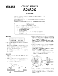
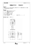
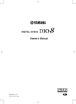
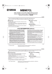
-EX
Owner’s Manual
V480360 R2 1 IP 16
200 CR Printed in Japan
E
FCC INFORMATION (U.S.A.)
1. IMPORTANT NOTICE: DO NOT MODIFY THIS UNIT! This product, when installed as indicated in the instructions contained in this manual, meets FCC
requirements. Modifications not expressly approved by Yamaha may void your authority, granted by the FCC, to use the product.
2. IMPORTANT: When connecting this product to accessories and/or another product use only high quality shielded cables. Cable/s supplied with this product MUST
be used. Follow all installation instructions. Failure to follow instructions could void your FCC authorization to use this product in the USA.
3. NOTE: This product has been tested and found to comply with the requirements listed in FCC Regulations, Part 15 for Class “B” digital devices. Compliance with
these requirements provides a reasonable level of assurance that your use of this product in a residential environment will not result in harmful interference with
other electronic devices. This equipment generates/uses radio frequencies and, if not installed and used according to the instructions found in the users manual, may
cause interference harmful to the operation of other electronic devices. Compliance with FCC regulations does not guarantee that interference will not occur in all
installations. If this product is found to be the source of interference, which can be determined by turning the unit “OFF” and “ON”, please try to eliminate the
problem by using one of the following measures: Relocate either this product or the device that is being affected by the interference. Utilize power outlets that are on
different branch (circuit breaker or fuse) circuits or install AC line filter/s. In the case of radio or TV interference, relocate/reorient the antenna. If the antenna lead-in
is 300 ohm ribbon lead, change the lead-in to coaxial type cable. If these corrective measures do not produce satisfactory results, please contact the local retailer
authorized to distribute this type of product. If you can not locate the appropriate retailer, please contact Yamaha Corporation of America, Electronic Service
Division, 6600 Orangethorpe Ave, Buena Park, CA 90620
The above statements apply ONLY to those products distributed by Yamaha Corporation of America or its subsidiaries.
WARNING: THIS APPARATUS MUST BE EARTHED
IMPORTANT
THE WIRES IN THIS MAINS LEAD ARE COLOURED IN
ACCORDANCE WITH THE FOLLOWING CODE:
GREEN-AND-YELLOW :
EARTH
BLUE :
NEUTRAL
BROWN :
LIVE
As the colours of the wires in the mains lead of this apparatus may
not correspond with the coloured markings identifying the terminals in
your plug, proceed as follows:
The wire which is coloured GREEN and YELLOW must be
connected to the terminal in the plug which is marked by the letter E
or by the safety earth symbol
or coloured GREEN and YELLOW.
The wire which is coloured BLUE must be connected to the terminal
which is marked with the letter N or coloured BLACK.
The wire which is coloured BROWN must be connected to the
terminal which is marked with the letter L or coloured RED.
ADVARSEL!
Lithiumbatteri—Eksplosionsfare ved fejlagtig
håndtering. Udskiftning må kun ske med batteri
af samme fabrikat og type. Levér det brugte
batteri tilbage til leverandoren.
VARNING
Explosionsfara vid felaktigt batteribyte. Använd
samma batterityp eller en ekvivalent typ som
rekommenderas av apparattillverkaren.
Kassera använt batteri enligt fabrikantens
instruktion.
VAROITUS
Paristo voi räjähtää, jos se on virheellisesti
asennettu. Vaihda paristo ainoastaan
laitevalmistajan suosittelemaan tyyppiin. Hävitä
käytetty paristo valmistajan ohjeiden
mukaisesti.
* This applies only to products distributed by YAMAHA KEMBLE
MUSIC (U.K.) LTD.
NEDERLAND
THE NETHERLANDS
● Dit apparaat bevat een lithium batterij voor geheugen
back-up.
● This apparatus contains a lithium battery for memory
back-up.
● Raadpleeg uw leverancier over de verwijdering van de
batterij op het moment dat u het apparaat ann het einde
van de levensduur afdankt of de volgende Yamaha Service
Afdeiing:
Yamaha Music Nederland Service Afdeiing
Kanaalweg 18-G, 3526 KL UTRECHT
Tel. 030-2828425
● For the removal of the battery at the moment of the
disposal at the end of the service life please consult your
retailer or Yamaha Service Center as follows:
Yamaha Music Nederland Service Center
Address: Kanaalweg 18-G, 3526 KL
UTRECHT
Tel: 030-2828425
● Gooi de batterij niet weg, maar lever hem in als KCA.
● Do not throw away the battery. Instead, hand it in as small
chemical waste.
Windows 95/98® is a registered trademark of Microsoft in the U.S.A. and other countries.
2
■ Precautions
• The digital circuits of this unit may induce a slight
noise into nearby radios and TVs. If noise occurs,
relocate the affected equipment.
• If the message “WARNING LOW BATTERY!” appears
when you turn on this unit, contact your dealer as
soon as possible about replacing the internal data
backup battery. The unit will still operate correctly,
but data other than the presets will be lost.
• Before you replace the battery, store your data to an
ATA-compliant PC flash storage card via the CS1D, or
store the data to the personal computer by connecting
the computer to the PC CONTROL “RS-232-C” connector on the DSP1D/DSP1D-EX.
• The unit is equipped with the ground connector to
avoid the risk of electrical shock.
• Be sure to ground the unit before you insert the power
plug into an AC outlet.
• If the power cord has three pins and the ground connector on the AC outlet is grounded, the unit will be
grounded effectively.
Operating Notes
• The power must be turned on/off using the POWER
switch of this unit. Do not turn the power on/off by
plugging in the power cable, or by using a power strip
or circuit breaker. Doing so may cause malfunctions.
• Do not rapidly turn on and off the POWER switch of
this unit. Doing so may cause excessive current to
damage the system. You must allow at least five seconds to elapse between power-on and power-off.
• For this unit, be sure to use a power voltage of the
value specified in the Specifications section of this
Owner’s Manual. If you apply a higher or lower voltage, a malfunction may result.
Rack Mounting Caution
If the unit is rack mounted and transported regularly,
for example, when on a tour, we recommend that the
rear of the unit be supported by fitting a pair metal
brackets, one each side. The following drawing provides the information necessary to make such brackets.
Note that only one bracket is shown here and the
bracket for the other side must be bent in the opposite
direction.
2-R2
2-R2
(82.1)
76.2
86.5
44.45
200
R2
134
3.1
R5
0
8
12
0
7.5
14.5
0
5.9
4- ø 6.5
20.5
31.75
36.5
• Do not place a container with liquid or small metal
objects on top of this unit. Liquid or metal objects
inside this unit are a fire and electrical shock hazard.
• Do not allow water to enter this unit or allow the unit
to become wet. Fire or electrical shock may result.
• Connect this unit’s power cord only to an AC outlet of
the type stated in this Owner’s Manual or as marked
on the unit. Failure to do so is a fire and electrical
shock hazard.
• Do not scratch, bend, twist, pull, or heat the power
cord. A damaged power cord is a fire and electrical
shock hazard.
• Do not place heavy objects, including this unit, on top
of the power cord. A damaged power cord is a fire and
electrical shock hazard. In particular, be careful not to
place heavy objects on a power cord covered by a carpet.
• Be sure to ground the unit to avoid the risk of electrical shock
• If you notice any abnormality, such as smoke, odor, or
noise, or if a foreign object or liquid gets inside the
unit, turn it off immediately. Remove the power cord
from the AC outlet. Consult your dealer for repair.
Using the unit in this condition is a fire and electrical
shock hazard.
• Should this unit/AC adapter/power supply be
dropped or the cabinet be damaged, turn the power
switch off, remove the power plug from the AC outlet,
and contact your dealer. If you continue using the unit
without heeding this instruction, fire or electrical
shock may result.
• If the power cord is damaged (i.e., cut or a bare wire is
exposed), ask your dealer for a replacement. Using the
unit with a damaged power cord is a fire and electrical
shock hazard.
• Do not remove the unit’s cover. You could receive an
electrical shock. If you think internal inspection,
maintenance, or repair is necessary, contact your
dealer.
• Do not modify the unit. Doing so is a fire and electrical shock hazard.
• When rack-mounting the unit, allow enough free
space around the unit for normal ventilation. This
should be: 10 cm behind, and 20 cm above.
• For normal ventilation during use, remove the rear of
the rack or open a ventilation hole.
• If the airflow is not adequate, the unit will heat up
inside and may cause a fire.
• This unit has ventilation holes at the rear and bottom
to prevent the internal temperature rising too high.
Do not block them. Blocked ventilation holes are a fire
hazard.
• Hold the power cord plug when disconnecting it from
an AC outlet. Never pull the cord. A damaged power
cord is a potential fire and electrical shock hazard.
• Do not touch the power plug with wet hands. Doing
so is a potential electrical shock hazard.
t = 1.6
3
Thank you for choosing the DSP unit “DSP1D/DSP1D-EX”, specifically designed for the Yamaha PM1D
digital audio mixing system. The DSP1D/DSP1D-EX is an engine controlled by the CS1D control surface.
Be sure to ask an authorized Yamaha service engineer to install the boards and
set up the unit. Never perform installation and setup by yourself.
The following optional boards can be installed in the DSP1D.
•
•
•
•
•
•
CIB1D : Console interface board
EMB1D : Engine management board
PDB1D : Patch DSP board
GDB1D : Group DSP board
EDB1D : Effect DSP board
IDB1D : Input DSP board
■ Front
panel
ENGINE ID
A
1
B
CONTROL I/O
1
ENGINE ID
A
2
2
B
CONTROL I/O
1
INPUT
CONFIGURATION
2
INPUT
CONFIGURATION
48CH
96CH
POWER
ON/ OFF
48CH
3
96CH
POWER
ON/ OFF
4
■ Rear
panel
MIDI
CONTROL I/O
CONSOLE
L M
1
N
O
IN
DIGITAL I/O
IN
5
OUT
OUT
8
OUTPUT
INPUT
CONSOLE
I/O
CASCADE
1
IN
5
3
1
9
7
5
3
1
2
OUT
6
4
2
10
8
6
4
2
2
IN
THRU
OUT
MIDI
DIGITAL I/O
CONTROL I/O
CONSOLE
PC
CONTROL
OUTPUT
INPUT
CONSOLE
I/O
CASCADE
1
IN
5
3
1
9
7
5
3
1
2
OUT
6
4
2
10
8
6
4
2
1
IN
IN
OUT
OUT
REMOTE
2
IN
THRU
OUT
PC
CONTROL
REMOTE
RS-232-C
RS-422
USB
2
9
2
RS-422
2
RS-232-C
2
6
GPI
WORD CLOCK
IN
75Ω
OFF
ON
2
2
2
2
TIME CODE IN
USB
OUT
GPI
WORD CLOCK
J
IN
7
75Ω
OFF
ON
TIME CODE IN
OUT
K
P
4
A ENGINE ID A/B indicators
These indicators indicate whether the DSP1D/
DSP1D-EX is connected to the engine A or engine B
channel.
Indicator A lights up if the DSP1D/DSP1D-EX is connected to the engine A channel jacks of the CS1D control surface (DIGITAL I/O jack A and CONTROL I/O
jack A). Indicator B lights up if the DSP1D/DSP1DEX is connected to the engine B channel jacks of the
CS1D control surface (DIGITAL I/O jack B and CONTROL I/O jack B).
Error indication
• If both ENGINE ID A and B indicators are flashing:
→ There is a malfunction in the internal board
(PDB, GDB, IDB1/2, EDB, EMB, or CIB). Or
the necessary board does not exist.
• If either ENGINE ID A or B indicator is flashing:
→ During the Mirror mode operation, the
ENGINE ID indicator for the unused DSP1D/
DSP1D-EX flashes, indicating that the unit is in
standby mode.
→ If Indicator A is flashing, unit A is in standby
mode. If Indicator B is flashing, unit B is in
standby mode.
B CONTROL I/O 1/2 indicators
These indicators indicate which one of two CONSOLE 1, 2 IN/OUT jacks (8) on the rear panel is currently effective.
Note:
When you turn on the power to the DSP1D/
DSP1D-EX and the CS1D, and communication
between the DSP1D/DSP1D-EX and the CS1D is
established, one of these two indicators lights up. If
neither one lights up, check the connection of the
CONSOLE 1, 2 IN OUT jacks on the rear panel.
D POWER ON/OFF switch
Use this switch to turn the power to the DSP1D/
DSP1D-EX on or off. When the power is turned on,
the indicators 1 - 3 light up.
E MIDI IN/OUT/THRU connectors
These connectors are used to transmit and receive
Program change messages, MMC, and other MIDI
messages among external MIDI devices.
F PC CONTROL RS-232-C/USB ports
Connect these ports to a PC that runs Windows 95 or
Windows 98 to control the PM1D system from the
PC. Use a D-sub, 9-pin cross cable (female to female)
to connect the RS-232-C port to the serial (COM)
port on the PC. The USB port is provided for future
system expansion, but it is not operative in the current
software version.
G WORD CLOCK IN jack, 75 Ω ON/OFF
switch, and WORD CLOCK OUT jack
The WORD CLOCK IN jack is used to provide word
clock to the PM1D system from the connected external device, such as a clock generator. Use the WORD
CLOCK OUT jack to provide the word clock to the
connected external device from the PM1D. Use a BNC
cable with an impedance of 75 Ω for the WORD
CLOCK IN/OUT jacks.
The WORD CLOCK ON/OFF switch is used to terminate the word clock connection. Basically, if the
DSP1D/DSP1D-EX is the last device of the word clock
chain, or if nothing is connected to the WORD
CLOCK IN/OUT jacks, set this switch to ON.
H CONSOLE 1, 2 IN/OUT jacks
These jacks are connected to the CONTROL I/O
CONSOLE jacks of the CS1D control surface to transmit or receive control signals. For connection, use a
genuine Yamaha cable or a BNC cable with an impedance of 50 Ω.
I REMOTE RS-422 connector
Error indication
• If the CONTROL I/O 1 indicator is flashing:
→ Communication between the CS1D control
surface and the DSP1D is not established.The
CONSOLE 1, 2 IN OUT jacks or the PC CONTROL port is not connected correctly.
C INPUT CONFIGURATION 48CH/96CH
indicators
These indicators indicate how many input channels
are currently available. On the DSP1D, the 48CH
indicator lights up. On the DSP1D-EX, the 96CH
indicator lights up.
Error indication
• If the INPUT CONFIGURATION 48CH is flashing:
→ The signal is not locking to the word clock.
This D-sub 9-pin connector is used to control a connected tape recorder or a hard disk recorder. Serial
commands can be transmitted through this connector
to play or stop such a recorder.
This connector is provided for future system expansion, but it is not operative in the current software
version.
J GPI connector
This connector is used to connect an external device
that supports GPI (General Purpose Interface), such
as a video editor to control the external device from
the PM1D system or to perform certain functions of
the PM1D system while controlling from the external
device. You can connect a custom-made external
switch here.
This connector is provided for future system expansion, but it is not operative in the current software
version.
5
K TIME CODE IN connector
N OUTPUT 1–6 slot
This balanced XLR3-31 connector receives SMPTE
time code (LTC) for analog input from the external
device. The rated input level is –10 dB, and the pin
assignment is as follows.
1=ground, 2=hot, 3=cold
Use these slots to connect the INPUT connectors of an
analog output unit AO8 series or DIO8 digital I/O
unit to output multi-channel digital audio signals
from the DSP1D/DSP1D-EX. Use a genuine Yamaha
half-pitch 68-pin cable for connection.
L CONSOLE I/O 1, 2 slots
O INPUT 1–10 slot
Connect these slots to the DIGITAL I/O CONSOLE
jacks of the CS1D control surface to transmit multichannel digital audio signals. Use a genuine Yamaha
half-pitch 68-pin cable for connection.
Use these slots to connect the OUTPUT connectors of
an analog input unit AI8 series or DIO8 digital I/O
unit series to input multi-channel digital audio signals
to the DSP1D/DSP1D-EX. Use a genuine Yamaha
half-pitch 68-pin cable for connection.
M CASCADE IN, OUT slots
Use one of these connectors to cascade two DSP1D/
DSP1D-EX units to transmit multi-channel digital
audio signals. Use a genuine Yamaha half-pitch 68-pin
cable to connect the CASCADE IN (or OUT) to the
CASCADE OUT (or IN) of another DSP1D/DSP1DEX.
These connectors are provided for future system
expansion, but they are not operative in the current
software version.
■
P Ground connector
Be sure to ground the unit to avoid the risk of electrical
shock before you insert the power plug into an AC outlet.
This product comes with a 3-pin power cord. If the
ground connector of the AC outlet has already been
grounded, the unit will be grounded effectively by
using the 3-pin power cord.
Grounding the unit is also effective for preventing
hum and other noise.
Specifications
Sampling frequency
Power supply
<External sync> 39.69 kHz – 50.88 kHz
<Internal sync> 44.1 kHz, 48 kHz
USA and Canada : 120 V, 60 Hz
Others : 230 V, 50 Hz
Power consumption
170 W
Dimensions (W × H × D)
480 mm × 408.7 mm × 460.8 mm
Weight
33 kg
Operating temperature
10 – 35˚C
Fan circuit
always fixed
Accessories
power cable 2.5 m × 1
Digital I/Os
I/O connectors
6
Level
Type
DIGITAL I/O INPUT 1 –10
RS-422
D-sub, half-pitch, 68-pin connector (female) × 10
DIGITAL I/O OUTPUT 1 – 6
RS-422
D-sub, half-pitch, 68-pin connector (female) × 6
DIGITAL I/O CASCADE IN, OUT
RS-422
D-sub, half-pitch, 68-pin connector (female) × 2
DIGITAL I/O CONSOLE I/O 1, 2
RS-422
D-sub, half-pitch, 68-pin connector (female) × 2
CONTROL I/O CONSOLE 1 IN, OUT
–0.225V — –1.825V/50 Ω
BNC connector × 2
CONTROL I/O CONSOLE 2 IN, OUT
–0.225V — –1.825V/50 Ω
BNC connector × 2
REMOTE RS-422
RS-422
D-sub, 9-pin connector (female)
GPI
C-MOS IN, Open collector OUT
1 pin: 150mA, 8pin total: 500mA
D-sub, 25-pin connector (female)
TIME CODE IN
SMPTE format, Nominal –10 dB/10 k Ω
XLR-3-31 type connector
MIDI IN, OUT, THRU
MIDI format
5-pin DIN connector × 3
PC CONTROL RS-232-C
RS-232-C
D-sub, 9-pin connector (male)
PC CONTROL USB
0V — 3.3V
B type USB connector
WORD CLOCK IN
TTL/75 Ω (ON/OFF)
BNC connector
WORD CLOCK OUT
TTL/75 Ω
BNC connector
Slots (for IDB1D board)
Unit
Input channel
DPS1D
INPUT 1-48 & ST IN 1-4*
DPS1D-EX
INPUT 1-96 & ST IN 1-8 (DSP1D + IDB1D for expansion)
*The DSP1D has an empty slot available for the IDB1D board.
460.8
Dimensions
450
■
480
ENGINE ID
A
B
CONTROL I/O
1
2
INPUT
CONFIGURATION
48CH
96CH
408.7
9.5
399.2
POWER
ON/ OFF
unit: mm
• Specifications and appearance are subject to change without notice for improvement.
• For European Model
Purchaser/User information specified in EN55103-1 and EN55103-2.
Inrush Current: 31A
Conformed Environment: E1, E2, E3 and E4.
7
YAMAHA CORPORATION
Pro Audio & Digital Musical Instrument Division
P.O. Box 3, Hamamatsu, 430-8651, Japan
-EX
取扱説明書
J
! 安全上のご注意 ―安全にお使いいただくため―
安全にお使いいただくため、ご使用の前にこの
「安全上のご注意」をよくお読みください。
またお読みになったあと、いつでも見られるところに必ず保存してください。
絵表示 この取扱説明書および製品への表示では、製品を安全に
正しくお使いいただき、あなたや他の人々への危害や財産への
損害を未然に防止するために、いろいろな絵表示をしています。
内容をよく理解してから本文をお読みください。
絵表示の例
:注意(危険・警告を含む)を促す事項
:決しておこなってはいけない禁止事項
:必ずおこなっていただく強制事項
プラグをコンセント
から抜け
警告
この欄に記載されている事項を無視して、誤った取扱いをすると、人が死亡または重傷を負う
可能性があります。
設置されるとき
●
●
●
●
この機器はAC100V専用です。それ以外の電
源(AC200V、船舶の直流電源など)では使用
しないでください。火災・感電の原因となり
ます。
この機器に水が入ったり、機器がぬれたりし
ないようご注意ください。火災・感電の原因
となります。雨天・降雪時や海岸・水辺での
使用はとくにご注意ください。
電源コードの上に重い物をのせないでくださ
い。コードに傷が付くと、火災・感電の原因
となります。とくに、敷物などで覆われた
コードに気付かずに重い物を載せたり、コー
ドが本機の下敷きになることのないよう、十
分にご注意ください。
この機器の上に水などの入った容器や小さな
金属物を置かないでください。こぼれたり、
中に入ったりすると、火災・感電の原因にな
ります。
ご使用になるとき
●
電源コードを傷つけたり、加工したり、無理
に曲げたり、ねじったり、引っ張ったり、加
熱したりしないでください。コードが破損し
て、火災・感電の原因になります。
●
この機器の裏ぶたやカバーは絶対に外さない
でください。感電の原因になります。
内部の点検・整備・修理が必要と思われると
きは、販売店にご依頼ください。
この機器を改造しないでください。火災・感
電の原因となります。
分解禁止
●
商標について
Windows 95/98®は米国マイクロソフト社の米国およびその他
の国における登録商標です。
2
アース線を接続する
●
雷が鳴りだしたら、早めに機器本体の電源ス
イッチを切り、電源プラグをコンセントから
抜いてください。
●
落雷のおそれがあるとき、電源プラグが接続
されたままならば、電源プラグには触れない
でください。感電の原因となります。
プラグをコンセント
から抜け
接触禁止
使用中に異常が発生したとき
●
断線・芯線の露出など、電源コードが傷んだ
ら、販売店に交換をご依頼ください。そのま
まで使用すると、火災・感電の原因となりま
す。
●
万一、この機器を落としたり、キャビネット
を破損した場合は、電源スイッチを切り電源
プラグをコンセントから抜いて販売店にご連
絡ください。そのまま使用すると、火災・感
電の原因となります。
●
煙が出る、変なにおいや音がするなどの異常
がみとめられたときや、内部に水などの異物
が入った場合は、すぐに電源スイッチを切
り、電源プラグをコンセントから抜いてくだ
さい。そのあと、販売店にご連絡ください。
異常状態のままで使用すると、火災・感電の
原因となります。
プラグをコンセント
から抜け
プラグをコンセント
から抜け
注意
この欄に記載されている事項を無視して、誤った取扱いをすると、人が傷害を負ったり、物的
損害が発生したりする可能性があります。
設置されるとき
●
●
●
電源プラグを抜くときは、電源コードを引っ
張らないでください。必ずプラグを持ってく
ださい。コードを引っ張ると、電源コードが
傷ついて、火災・感電の原因となることがあ
ります。
濡れた手で電源プラグを抜き差ししないでく
ださい。感電の原因となることがあります。
この機器の通風孔をふさがないでください。
内部の温度上昇を防ぐため、この機器のケー
スの後、底部には通風孔があけてあります。
通風孔がふさがると内部に熱がこもり、火災
の原因となることがあります。
とくに次のような使い方は避けてください。
・ 機器をあお向けや横倒し、逆さまにする。
・ 本箱や押し入れなど、専用ラック以外の風
通しの悪い狭いところに押し込める。
・ テーブルクロスを掛けたり、じゅうたんや
布団の上に置いて使用する。
●
●
●
アース線を接続する
この機器は重いので、持ち運びは必ず2人以上
でおこなってください。
オーディオラックなどに入れるときは、放熱
をよくするために、壁や他の機器との間に隙
間をとってください。隙間の大きさは、背面
では10cm、天面では20cm以上必要です。
さらにラックの背面を開放するか、もしくは
ラックの背面に相当の通風孔を開けてくださ
い。
放熱が不十分だと内部に熱がこもり、火災の
原因となることがあります。
本機には感電防止のため、専用のアース端子
が設けられています。
電源プラグをコンセントに挿入する前に確実
に大地アースを施してください。
3芯電源コードの場合にはコンセント側のアー
ス端子が大地と接地されていれば上記と同じ
効果があります。
! 使用上のご注意 ―正しくお使いいただくため―
電源の投入について
バックアップ電池について
◆ この機器に電源を入れたとき、コントロールサーフェス
CS1D上に“WARNING LOW BATTERY!”という、メッ
セージが出たら、なるべく早く、お買上げ販売店へ電池の
交換を依頼してください。この機器に内蔵されているデー
タバックアップ用の電池が消耗しています。電池が古く
なっても、機器は正常に動作しますが、やがて、プリセッ
トプログラム以外のデータが消えてしまいます。
他の電気機器への影響について
◆ 電源のオン/オフは、必ず本機のPOWERスイッチで行っ
てください。電源コードの抜き差し、OAタップのスイッ
チ、ブレーカのスイッチなどでオン/オフはしないでくだ
さい。故障の原因となることがあります。
◆ 本機のPOWERスイッチを素早くオン/オフしないでくださ
い。過大電圧により本機が損傷する場合があります。オフ
からオンする間隔は、最低5秒間はとって行ってください。
◆ 本機は必ず本取説の仕様に記載されている電源電圧でご使
用ください。記載されている数値よりも高い電圧、あるい
は低い電圧で使用すると故障の原因となります。
◆ この機器のデジタル回路から発生するわずかな雑音が、近
くのラジオやテレビに入る可能性があります。そのような
ときは、両者を少し離してください。
2-R2
ラックマウント時のご注意
2-R2
ツアーなどでラックマウントしたまま頻繁に運搬される場
合には図のような金具を製作して本機のリア部を支えてく
ださい。
尚、本図は片側の金具の形状を示したものですので本図と
対称形状のものを同時に製作ください。
(82.1)
76.2
86.5
44.45
200
R2
134
3.1
R5
0
8
12
0
7.5
14.5
36.5
0
5.9
4- ø 6.5 孔
20.5
31.75
t = 1.6
3
この度はヤマハデジタルオーディオミキシングシステムPM1D専用DSPユニットDSP1D/DSP1D-EXを
お買い上げいただきありがとうございます。
DSPユニット DSP1D/DSP1D-EXはコントロールサーフェスCS1Dでコントロールするエンジンです。
ボードの装着、ユニットの設置などはヤマハサービスエンジニアにご依頼ください。
決してお客様ご自身で行なわないでください。
DSP1Dに装着される各種ボードは以下です。
これらのボードはオプションとしてもお求めになれます。
・CIB1D ― コンソール インタフェース ボード
・EMB1D ― エンジン マネージメント ボード
・PDB1D ― パッチ DSP ボード
・GDB1D ― グループ DSP ボード
・EDB1D ― エフェクト DSP ボード
・IDB1D ― インプット DSP ボード
■
フロントパネル
ENGINE ID
A
1
B
CONTROL I/O
1
ENGINE ID
A
2
2
B
CONTROL I/O
1
INPUT
CONFIGURATION
2
INPUT
CONFIGURATION
48CH
96CH
POWER
ON/ OFF
48CH
3
96CH
POWER
ON/ OFF
4
■
リアパネル
MIDI
CONTROL I/O
CONSOLE
L M
1
N
O
IN
DIGITAL I/O
IN
5
OUT
OUT
8
OUTPUT
INPUT
CONSOLE
I/O
CASCADE
1
IN
5
3
1
9
7
5
3
1
2
OUT
6
4
2
10
8
6
4
2
2
IN
THRU
OUT
MIDI
DIGITAL I/O
CONTROL I/O
CONSOLE
PC
CONTROL
OUTPUT
INPUT
CONSOLE
I/O
CASCADE
1
IN
5
3
1
9
7
5
3
1
2
OUT
6
4
2
10
8
6
4
2
1
IN
IN
OUT
OUT
REMOTE
2
IN
THRU
OUT
PC
CONTROL
REMOTE
RS-232-C
RS-422
USB
2
9
2
RS-422
2
RS-232-C
2
6
GPI
WORD CLOCK
IN
75Ω
OFF
ON
2
2
2
2
TIME CODE IN
USB
OUT
GPI
WORD CLOCK
J
IN
7
75Ω
OFF
ON
TIME CODE IN
OUT
K
P
4
1 ENGINE ID A/B インジケーター
DSP1D/DSP1D-EXが、
システム内でエンジンAま
たはエンジンBのどちらの系列に接続されているかを
表すインジケーターです。
コントロールサーフェスCS1DのENGINE A系の端子
(DIGITAL I/O端子AおよびCONTROL I/O端子A)
に接続されているDSP1D/DSP1D-EXではAのイン
ジケーターが、ENGINE B系の端子
(DIGITAL I/O端
子BおよびCONTROL I/O端子B)
に接続されている
DSP1D/DSP1D-EXではBのインジケーターが点灯
します。
エラー表示
・ ENGINE ID A/B両方のインジケーターが点滅
→ 内蔵ボード(PDB, GDB, IDB1/2, EDB, EMB, CIB)
の動作に異常がある。
または、必要なボードが存在し
ていない。
・ ENGINE ID A/Bどちらかのインジケーターが点
滅
→ミラーモードで使用時、実際に使用されていない方の
DSP1D/DSP1D-EXのENGINE IDインジケーターが
点滅し、そのユニットが待機状態であることを示しま
す。
待機状態がAの場合はENGINE ID Aインジケーター
が点滅し、Bの場合はENGINE ID Bが点滅します。
2 CONTROL I/O 1/2 インジケーター
リアパネルにある2系統のCONSOLE 1, 2 IN/OUT 端
子
(⑧)
のうち、現在有効となっている端子を表すイン
ジケーターです。
【注意】
DSP1D/DSP1D-EXとCS1Dの電源をオンにして、
DSP1D/DSP1D-EXとCS1Dとの間でコミュニケー
ションが確立できると、
どちらか一方のインジケーター
が点灯します。
インジケーターがどちらも点灯しないと
きは、DSP1DとCS1DのリアパネルのCONSOLE 1, 2
IN/OUT端子同士の接続を確認してください。
エラー表示
・ CONTROL I/O 1のインジケーターが点滅
→ コントロールサーフェスCS1DとDSP1D間のコミュニ
ケーションができていない。
C O N S O L E 1 , 2 I N / O U T 端子、あるいはP C
CONTROL 端子が正しく接続されていない。
3 INPUT CONFIGURATION 48CH/96CH インジ
ケーター
現在使用可能なインプットチャンネル数を表すインジ
ケーターです。DSP1Dでは48CH、DSP1D-EXでは
96CHのインジケーターが点灯します。
エラー表示
・ INPUT CONFIGURATION 48CHのインジケーター
が点滅
→ ワードクロックがロックしていない。
4 POWER ON/OFF スイッチ
DSP1D/DSP1D-EXの電源スイッチです。
電源オンのとき①∼③のインジケーターが点灯します。
5 MIDI IN/OUT/THRU 端子
外部MIDI機器との間でプログラムチェンジなどの
MIDIメッセージを送受信するための端子です。
6 PC CONTROL RS-232-C/USB 端子
Windows95/Windows98が動作するPC(パーソナル
コンピューター)
を接続し、PCからPM1Dシステムをコン
トロールするための端子です。RS-232-C端子は、D-sub
9ピンクロスケーブル
(メス← →メス)
を使ってPCのシリ
アル
(COM)
端子と接続してください。USB端子は現在
のソフトウェアバージョンでは動作していません。将来
の拡張のために用意されています。
7 WORD CLOCK IN 端子、75ΩON/OFF スイッチ、
WORD CLOCK OUT 端子
WORD CLOCK IN端子は、
クロックジェネレーターの
外部機器からPM1Dシステムにワードクロックを供給す
るための端子です。
また、PM1Dシステムからワードク
ロックを外部機器に供給する場合は、WORD CLOCK
OUT端子を使用します。WORD CLOCK IN/OUT端子
の接続には、
インピーダンス75ΩのBNCケーブルをご
使用ください。
75Ω ON/OFFスイッチは、
ワードクロック接続の終端処
理を行うためのスイッチです。原則として、DSP1D/
DSP1D-EXがワードクロック接続の終端となる場合、お
よびWORD CLOCK IN/OUT端子に何も接続しない
場合はONに設定します。
8 CONSOLE 1, 2 IN/OUT 端子
コントロールサーフェスC S 1 D のC O N T R O L I / O
CONSOLE端子と接続し、
コントロール信号を送受信
するための端子です。接続にはヤマハ純正ケーブルも
しくは50ΩBNCケーブルをご使用ください。
9 REMOTE RS-422 端子
テープレコーダーやHDレコーダーをコントロールするた
めのD-sub 9ピンコネクターです。
シリアルコマンドでレ
コーダーのPLAY, STOP等のコントロールが可能です。
この端子は現在のソフトウェアバージョンでは動作して
いません。将来の拡張のために用意されています。
J GPI 端子
ビデオ編集機などGPI(General Purpose Interface)
に
対応した外部機器を接続し、PM1Dシステムから外部
機器を制御したり、逆に外部機器からPM1Dシステム
の任意の機能を実行するための端子です。外付けス
イッチをカスタムメードして接続できます。
この端子は現在のソフトウェアバージョンでは動作して
いません。将来の拡張のために用意されています。
5
K TIME CODE IN 端子
N OUTPUT 1~6 スロット
外部機器からアナログ入力のSMPTEタイムコード
(LTC)
を受信するバランスのXLR3-31タイプ端子で
す。定格入力レベルは−10dBで、
ピンの配置は次の
通りです。
アナログアウトプットユニットAO8シリーズや、デジタ
ルI/OユニットDIO8のINPUT端子と接続し、DSP1D
/DSP1D-EXからマルチチャンネルのデジタルオー
ディオ信号を出力するための端子です。接続にはヤ
マハ純正のハーフピッチ68ピンケーブルのみをご使
用ください。
1=グランド、2=ホット、3=コールド
L CONSOLE I/O 1、2 スロット
コントロールサーフェスC S 1 D のD I G I T A L I / O
CONSOLE端子と接続し、マルチチャンネルのデジ
タルオーディオ信号をやり取りする端子です。接続に
はヤマハ純正のハーフピッチ68ピンケーブルのみを
ご使用ください。
O INPUT 1~10 スロット
アナログインプットユニットAI8シリーズや、デジタルI/
OユニットDIO8のOUTPUT端子と接続し、DSP1D/
DSP1D-EXにマルチチャンネルのデジタルオーディ
オ信号を入力するための端子です。接続にはヤマハ
純正のハーフピッチ68ピンケーブルのみをご使用く
ださい。
M CASCADE IN、OUT スロット
2台のDSP1D/DSP1D-EXをカスケード接続し、マル
チチャンネルのデジタルオーディオ信号をやり取りす
る端子です。ヤマハ純正のハーフピッチ68ピンケー
ブルを使って、CASCADE IN端子とCASCADE
OUT端子同士を接続してください。
この端子は現在のソフトウェアバージョンでは動作し
ていません。将来の拡張のために用意されています。
■
P アース端子
感電防止のため、電源プラグをコンセントに挿入する
前に確実に大地アースを施してください。
本機には3芯電源コードを付属しています。
この場合
にはコンセント側のアース端子が大地と接地されて
いれば上記と同じ効果があります。
ハムや雑音防止のためにも有効です。
仕様
サンプリング周波数
<External> 39.69 kHz ∼ 50.88 kHz <Internal> 44.1 kHz, 48 kHz
電源
100V, 50/60Hz
消費電力
150W
外形寸法(W×H×D)
480mm×408.7mm×460.8mm
重量
33kg
動作環境
10 ∼35℃
冷却ファンスピード
常時固定
付属品
電源コード 2.5m×1本、アダプター1個
入出力仕様
入出力端子
DIGITAL I/O INPUT 1-10
6
レベル
RS-422
コネクター
D-subハーフピッチ68ピンコネクター
(メス)
×10
DIGITAL I/O OUTPUT 1-6
RS-422
D-subハーフピッチ68ピンコネクター
(メス)
×6
DIGITAL I/O CASCADE IN, OUT
RS-422
D-subハーフピッチ68ピンコネクター
(メス)
×2
DIGITAL I/O CONSOLE I/O 1, 2
RS-422
D-subハーフピッチ68ピンコネクター
(メス)
×2
CONTROL I/O CONSOLE 1 IN, OUT
−0.225V ∼ −1.825V/50 Ω
BNCコネクター×2
CONTROL I/O CONSOLE 2 IN, OUT
−0.225V ∼ −1.825V/50 Ω
BNCコネクター×2
REMOTE RS-422
RS-422
D-sub 9ピンコネクター
(メス)
GPI
C-MOS IN, Open collector OUT
1ピン: 150 mA、8ピン:トータル 500 mA
D-sub 25ピンコネクター
(メス)
TIME CODE IN
SMPTEフォーマット、定格 −10 dB/10 kΩ
XLR-3-31タイプコネクター
MIDI IN, OUT, THRU
MIDIフォーマット
DIN 5ピンコネクター×3
PC CONTROL RS-232-C
RS-232-C
D-sub 9ピンコネクター
(オス)
PC CONTROL USB
0V − 3.3V
BタイプUSBコネクター
WORD CLOCK IN
TTL/75 Ω (ON/OFF)
BNCコネクター
WORD CLOCK OUT
TTL/75 Ω
BNCコネクター
スロット (IDB1Dボード用)
ユニット名
インプットチャンネル
DSP1D
INPUT 1∼48 & ST IN 1∼4※
DSP1D-EX
INPUT 1∼96 & ST IN 1∼8(DSP1D + 増設IDB1D)
※ DSP1DはIDB1Dボード用空スロット有り
450
460.8
寸法図
480
ENGINE ID
A
B
CONTROL I/O
1
2
INPUT
CONFIGURATION
48CH
96CH
9.5
408.7
POWER
ON/ OFF
399.2
■
単位:mm
・ 仕様および外観は改良のため予告なく変更することがあります。
・ 高調波ガイドライン適合品
7
サービスについて
■ 保証書
■ 調整・故障の修理
この商品には保証書がついています。販売店でお渡ししてい
ますから、
ご住所・お名前・お買上げ年月日・販売店名など所定
事項の記入および記載内容をおたしかめのうえ、大切に保管し
てください。
保証書は当社がお客様に保証期間内の無償サービスをお約
束するもので、
この商品の保証期間はお買上げ日より1年です。
保証期間内の転居や、
ご贈答用に購入された場合などで、記
載事項の変更が必要なときは、事前・事後を問わずお買上げ販
売店かお客様ご相談窓口、
またはヤマハ電気音響製品サービス
拠点へご連絡ください。継続してサービスできるように手配いた
します。
「故障かな?」
と思われる症状のときは、
この説明書をもう一度
よくお読みになり、電源・接続・操作などをおたしかめください。
そ
れでもなお改善されないときには、お買上げ販売店へご連絡く
ださい。調整・修理いたします。
調整・修理にさいしては保証書をご用意ください。保証規定に
より、調整・修理サービスをいたします。
また、故障した製品をお
持ちいただくか、サービスにお伺いするのかも保証書に書かれ
ています。
修理サービスは保証期間が過ぎた後も引き続きおこなわれ、
そのための補修用性能部品が用意されています。性能部品とは
製品の機能を維持するために不可欠な部品のことをいい、PA製
品ではその最低保有期間は製造打切後8年です。
この期間は経
済産業省の指導によるものです。
■ 損害に対する責任
この商品
(搭載プログラムを含む)
の使用または使用不能に
より、お客様に生じた損害
(事業利益の損失、事業の中断、事業
情報の損失、
その他の特別損失や逸失利益)
については、当社は
一切その責任を負わないものとします。
また、如何なる場合でも、
当社が負担する損害賠償額は、お客様がお支払になったこの商
品の代価相当額をもって、
その上限とします。
■ お客様ご相談窓口
ヤマハPA製品にかんするご質問・ご相談は下記のお客様ご
相談窓口へ、アフターサービスについてのお問合わせはヤマハ
電気音響製品サービス拠点へおよせください。
●お客様ご相談窓口 : ヤマハプロオーディオ製品に対するお問合せ窓口
ヤマハ・プロオーディオ・インフォメーションセンター
Tel: 03-5791-7678 Fax: 03-5488-5085(電話受付=祝祭日を除く月∼金/11:00∼19:00)
E-mail: [email protected]
●EM営業統括部(営業窓口)
営業推進課(プロオーディオ)
PA営業部
東日本営業所
PA北海道
PA仙台
西日本営業所
PA名古屋
PA九州
☎
03-5488-5472
〒108-8568
東京都港区高輪2-17-11
☎
☎
☎
☎
☎
☎
03-5488-5480
011-512-6106
022-222-6214
06-6252-5405
052-232-5744
092-412-5556
〒108-8568
〒064-0810
〒980-0804
〒542-0081
〒460-8588
〒812-8508
東京都港区高輪2-17-11
札幌市中央区南十条西1-1-50
仙台市青葉区大町2-2-10
大阪市中央区南船場3-12-9
名古屋市中区錦1-18-28
福岡市博多区博多駅前2-11-4
☎
053-460-2455
〒430-8650
浜松市中沢町10-1
●PA・DMI事業部
PE営業部PA国内推進室
●ヤマハ電気音響製品サービス拠点 : 修理受付および修理品お預かり窓口
北海道サービスステーション
仙 台サービスステーション
首都圏サービスセンター
浜 松サービスステーション
名古屋サービスセンター
大 阪サービスセンター
四 国サービスステーション
広 島サービスステーション
九 州サービスステーション
本 社/CSセンター
☎
☎
☎
☎
☎
☎
☎
☎
☎
☎
011-512-6108
022-236-0249
03-5762-2121
053-465-6711
052-652-2230
06-6877-5262
087-822-3045
082-874-3787
092-472-2134
053-465-1158
〒064-8543
〒984-0015
〒143-0006
〒435-0016
〒454-0058
〒565-0803
〒760-0029
〒731-0113
〒812-8508
〒435-0016
札幌市中央区南十条西1-1-50 ヤマハセンター内
仙台市若林区卸町5-7 仙台卸商共同配送センター 3F
東京都大田区平和島2-1-1 京阪トラックターミナル14号棟A-5F
浜松市和田町200 ヤマハ(株)和田工場6号館2階
名古屋市中川区玉川町2-1-2 ヤマハ(株)名古屋流通センター3F
吹田市新芦屋下1-16 ヤマハ(株)千里丘センター内
高松市丸亀町8-7 (株)ヤマハミュージック神戸 高松店内
広島市安佐南区西原6-14-14
福岡市博多区博多駅前2-11-4
浜松市和田町200 ヤマハ(株)和田工場6号館2階
※ 所在地・電話番号などは変更されることがあります。
※ 2001年8月現在