1
空調機用通信インターフェイス
COMMUNICATION INTERFACE FOR AIR-CONDITIONER
取 扱 説 明 書
INSTRUCTION MANUAL
CHC-MJ4
CHC-MJ8
このたびは三菱重工空調機用通信インターフェイスをお買い上げいただき,まことにあり
がとうございました。
ご使用前にこの取扱説明書をよくお読みいただき,正しくご使用ください。お読みになったあと
は保証書とともに大切に保管してください。万一,ご使用中にわからないことや異常が生じたと
ききっとお役にたちます。なお,エアコンに付属している取扱説明書も合わせてお読み下さい。
Thank you very much for employing Communication Interface for Air-conditioner of
Mitsubishi Heavy Industries, Ltd.
Before operation, read through this instruction manual for proper operation. After reading through it,
carefully store it for the future reference. If any trouble should occur during operation, it will be
helpful. Also read through the instruction manual which is appended to the air-conditioner.
PSZ012A022
B
■ 安全上のご注意
■ご使用の前に,この「安全上のご注意」をよくお読みのうえ正しくお使いください。
■ここに示した注意事項は,「 警告」,「 注意」に区分していますが,誤った取り扱いをしたときに,
死亡や重傷等の重大な結果に結び付く可能性が大きいものを特に「 警告」の欄にまとめて記載してい
ます。しかし,「 注意」の欄に記載した事項でも,状況によっては重大な結果に結び付く可能性があ
ります。いずれも安全に関する重要な内容を記載していますので,必ず守ってください。
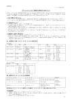
■本文中に使われる“図記号”の意味は次のとおりです。
絶対に行わないで
必ず指示に従い,
必ずアース線工事を
ください。
行ってください。
行ってください。
■お読みになった後は,お使いになる方がいつでも見られる所に必ず保管してください。また,お使いに
なる方が代わる場合は,必ず本書をお渡しください。
■ 据え付け上の注意事項
警告
取り付けは,お買い上げの販売店に依頼してください。
ご自分で取り付けをされ不備があると,感電,火災などの原因になります。
注意
可燃性ガスの漏れるおそれのある場所への設置
は行わないでください。
アース工事を行ってください。
万一ガスが漏れてユニットの周囲に溜まると,発火
の原因になることがあります。
■ 使 用 上 の注 意 事 項
注意
濡れた手でスイッチを操作しないでください。
接続線を引っ張らないでください。
感電の原因になることがあります。
心線の一部が断線して漏電の原因に
なることがあります。
■取り付けについて
ノイズが発生するところに取り付
けないでください。
湿気の多いところや,振動の大
きいところに取り付けないでくだ
さい。
直射日光があたるところや熱源
の近くはさけてください。
コンピュータ,自動ドア,エレベ
ータなどノイズが発生する機器
の近くに取り付けますと,誤作動
の原因になります。
湿気の多いところ,水のかかると
ころおよび振動の大きいところ
に取り付けますと,故障の原因に
なります。
直射日光があたるところや熱源
の近くに取り付けますと,故障の
原因になります。
- 1-
1.
仕
様
項
使
用
時
周
目
仕
囲
温
度
0℃~40℃
様
電
源
電
圧
単相 AC200V~240V±10%
消
費
電
力
35W
法
200(H)×330(W)×180(D)mm (CHC-MJ4)
寸
50/60Hz
200(H)×470(W)×180(D)mm (CHC-MJ8)
重
量
6.2 kg (CHC-MJ4)
8.6 kg (CHC-MJ8)
端
子
台
引
張
強
度
積 算 電 力 量 計 パ ル ス 入 力
最大 10kg
最大 4 点,無電圧a接点,DC24V,20mA
パルス巾:100ms 以上
パッケージエアコン最大接続台数
48 台/系統×4系統=192 台 (CHC-MJ4)
48 台/系統×8系統=384 台 (CHC-MJ8)
C H C と M I G と の 通 信
最大 250 ブロック,1ブロック当り最大 64 グループとし,
1グループ当り 16 台の空調機で構成されます。
注 意
本ユニットの空調料金計算は計量法によるものではありません。
- 2-
2.
はじめに
このたびは,空調機用通信インターフェース(以下 CHC-MJ と称します)をお買い上げいただき,
誠にありがとうございます。
ご使用の前に,この説明書をよくお読みいただき,正しくお使い下さい。
3.
本機の特徴
本装置は,ジョンソンコントロールズ社製 BA システム(METASYS-J)との通信によりパッケージ・
エアコンの監視制御を行うもので,以下の構成,機能を有するものです。
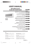
(1) システム構成図
ジョンソン
三菱重工業㈱側
コントロールズ㈱側
中央監視盤
(METASYS―J)
ホスト側
I/F(MIG)
AC200-240V
電力量計パルス(a 接点,最大4点)
SL1
RS232C
CHC
-MJ4
•••
48 台
•••
48 台
•••
48 台
•••
48 台
•••
48 台
•••
48 台
•••
48 台
•••
48 台
SL2
CHC
-MJ8
SL3
SL4
【注
意】
図に示す室内機接続台数は,最大接続台数
です。下記,①~⑧による制限とホスト機お
よびホスト側 I/F の処理能力により接続台
数が変わります。
実際の室内機接続台数については,ホスト機
側メーカと調整願います。
また,5,8,10 馬力の GHP 室外機が1
台でも混在するときは,室内機 48 台が 44 台
となります。最大接続台数 192 台が 176 台,
384 台が 352 台となります。
他の弊社制御機器と併用の場合は P7の接続
制限を参照下さい。
SL5
SL6
SL7
SL8
室内機最大接続数 CHC-MJ4 は 192 台,CHC-MJ8 は 384 台
① CHC とホスト(MIG)との通信は,ブロック単位の情報伝達です。
(空調機の異常に関してもブロック単位)
② 1ブロック当り最大 64 グループまで登録できます。
③ 1グループの最小は,1リモコングループ。
④ 1グループの最大は,16 台。
⑤ 1グループに異なる SL 系統の空調機を登録する事は禁止です。
⑥ ブロック,グループの定義は CHC 側で設定し,E2PROM によりバックアップします。
⑦ グループ定義において室外機グループ(冷媒配管系統)による制約はありません。
⑧ ブロックは最大 250 ブロック,グループは最大 256 グループです。
- 3-
(2)CHC-MJ の機能
CHC-MJ は,パッケージエアコンのローカル制御,BA システムとデータ伝送を行うもので次の
機能を持ちます。
① パッケージエアコン発停操作
中央監視盤からの発停指令によりブロック毎の発停を行います。
② 温度設定
中央監視盤からの個別設定指令によりブロック毎の温度を設定します。設定温度は1℃きざ
みで 18℃~30℃の範囲です。
③ 運転モード切換
中央監視盤からの個別切換信号によりブロック毎の運転モード(冷房,暖房,送風,自動)
を設定します。
④ リモコンモード設定
中央監視盤からの個別切換信号によりブロック毎の手元リモコンの許可(『センター&リモ
ート』),禁止(『センター』)を設定します。
⑤ フィルターサイン(警報)リセット
パッケージエアコンから送信されたフィルターサイン(警報)を中央監視盤からの指示によ
りリセットします。
⑥ 電力デマンド制御
中央監視盤からの設定指令によりブロック毎に設定します。
電力デマンド制御時,空調機の運転モードは『送風』,リモコンモード設定は『センター』
(リモコン操作禁止)となります。
電力デマンド制御解除時,電力デマンド制御開始前の状態に復帰します。
⑦ 火災制御(強制一斉停止)
中央監視盤からの火災信号により,パッケージエアコンを『センター』(リモコン操作禁止)
とし,一括停止します。
中央監視盤からの火災解除信号により,パッケージエアコンを停止状態にて火災前の設定状
態にて一括復帰させます。
⑧ 監視情報伝送(状態のサンプリングタイムは4分です)
(イ) 運転/停止状態,異常発生状態,設定温度,運転モード,室内温度のパッケージエアコ
ンブロック毎のデータを中央監視盤に伝送します。
(ロ) パッケージエアコンの異常の有無のデータをパッケージエアコンブロック毎に中央監視
盤に伝送します。
(ハ) パッケージエアコンからのフィルターサイン(警報)を中央監視盤にブロック毎に伝送
します。
⑨ 計量データ伝送
パッケージエアコンの運転状態に基づき消費電力量の按分計算を行い,その按分電力量の積
算値をブロック毎に中央監視盤に伝送します。積算電力量のデータ範囲は 0.0kWh~
99999.9kWh で,月単位等の使用電力量の算出は中央監視盤にて行います。
⑩ 停電補償
(イ) 設定データ(ブロック毎のグループ No.指定,ブロック毎の代表グループ No.指定,グル
ープ毎の空調機 No.指定,グループ毎の代表空調機 No.指定,空調機毎の機種設定,電力パ
ルス入力設定値)は,不揮発性メモリ(E2PROM)により補償します。
(ロ) 空調機毎の運転/停止,設定モード(室温設定,運転モード,センター/リモート)及
び電力量積算値は 48 時間補償します。(48 時間充電,バッテリ寿命 10 年)
- 4-
4.
結線要領
(1) スーパーリンク用信号線
● サイズ:0.75mm2 ~2.0mm2
● 許容延長長さ:1000m 以内/1系統当り
● 配線材料:標準線(ノイズの影響の有る場合はシールド線をご使用ください。)
● 推奨信号線
No.
名
称
記
号
1
ビニルキャブタイヤ丸形コード
VCTF
2心 0.75 ~ 2mm2
2
ビニルキャブタイヤ丸形ケーブル
VCT
2心 0.75 ~ 2mm2
3
制御用ビニル絶縁ビニルシースケーブル
CVV
2心 0.75 ~ 2mm2
4
シールド線
MVVS
2心 0.75 ~ 2mm2
No.4シールド線を用いた場合,電源線との区別が明確なため AC200 又は AC100V
との誤接続防止に役立ちます。
注1) 多芯コードによる電源線(200V)との混在使用は絶対行わないで下さい。
注2) 単芯コード2本を信号線として使用することは誤動作の原因となります。
(2) 電力量計パルス信号線
● サイズ: 0.75mm2×2 心又はφ0.9~φ1.2×2 心
- 5-
(3) 適合圧着端子
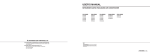
(4) 結線処理について
• 下図の様に付属のフィルタ・コアにスーパーリンク信号線を2~3回巻き付けて下さい。
2~3回巻き付けて下さい。
スーパーリンク信号線
(5)
CHC-ホスト側 I/F 間の RS232C ケーブルは,15m 以内として下さい。
- 6-
ご
注
意
(1)CHC-MJ 接続時,センターコンソール(SL-Ⅲ,SLA-200 シリーズ),料金管理システム(RKS
シリーズ),及びネットワークリモコンと併用はできません。
注 1)SLA-1,SLA-2A を併用する場合は下表の個数制限があります。
スーパーリンク 1 系統あたり
CHC
SLA-2A
SLA-1
1個
2個
0個
1個
1個
2個
1個
0個
3個
注 2)SLA-2A を接続した時,『センター』『センター/リモート』の設定は,CHC と SLA-2A
を同じ設定にして下さい。(同じ設定にしないと設定モードが確定できません)
注 3)5,8,10 馬力の GHP 室外機が1台でも混在するとき室内機は下表の台数制限となり
ます。
スーパーリンク 1 系統あたり
SLA-2A 接続個数
室内機最大接続台数
0個
44 台
1個
32 台
2個
21 台
また,SLA-1 との併用はできません。
(2)配線工事の際,CHC-MJ の端子台に無理な荷重がかからないようケーブルの結束処理を行って
下さい。
5.
CHC-MJ をご使用になるにあたって
(1) 各空調機毎のブロック登録については代理店または販社に依頼して下さい。
(2) 一度,空調機登録が終了しますと,48 時間以上の停電時にも再度登録しなおす必要は有りませ
ん。但し,CHC-MJ の故障,又はテナント変更が発生した場合のために,登録データは保管する
様にして下さい。
- 7-
6.
外形図
- 8-
7.
サービス・スペース
(
)内数値は CHC-MJ8 を示します。
- 9-
8.
故障表示一覧
CPU ユニット部および SLG ユニット部の緑 LED(電源表示およびマイコン正常表示灯)赤 LED(異
常表示灯),黄 LED(通信モニタ)の表示内容により,異常の有無が判ります。
表示 LED
「RUN」(緑)
表示状態
連続点滅
連続点灯
または消灯
消灯
CPU ユニット
1回点滅
「ALRM」(赤)
3回点滅
連続点滅
「COM-SD」(黄)
「COM-RD」(黄)
消
灯
連続点灯
「RUN」(緑)
SLG ユニット
「ALRM」(赤)
連続点滅
連続点灯
または消灯
消灯
1 回点滅
2回点滅
連続点滅
「COM-LCL」(黄) 連続点灯
または消灯
連続点滅
「COM-PAC」(黄) 連続点灯
または消灯
故障内容
正常
CPU ユニットは基板不良,CPU 暴走
正常
<対 SLG ユニット通信異常>
① CPU ユニット基板不良
② SLG ユニット基板不良
③ 内部結線不良
<ホスト故障>
① ホスト側故障
② ホスト間結線不良
③ CPU ユニット基板不良
④ 内部結線不良
正 常(ホストとの通信中)
① ホスト側電源 OFF 又は故障
② ホスト側通信停止(オフライン)
③ ホスト間結線不良
① ホスト側故障
② ホスト間結線不良
③ CPU ユニット基板不良
正 常
SLG ユニット基板不良,CPU 暴走
正 常
<対空調機通信異常>
① SLG ユニット基板不良
② 空調機コントロール基板不良
③ スーパーリンク通信線結線不良
<スーパーリンク通信線結線不良>
① SL 系統またぎ
正 常(CPU ユニットとの通信中)
① CPU ユニット基板不良
② SLG ユニット基板不良
③ 内部結線不良
正 常(空調機との通信中)
① SLG ユニット基板不良
② 空調機コントロール基板不良
③ スーパーリンク通信線結線不良
- 10-
SAFETY PRECAUTIONS
■Before starting to use the system, read carefully this "SAFETY PRECAUTIONS" to ensure a proper
operation of the system.
■Safety precautions described here are classified to " WARNING" and " CAUTION". Precautions which are
shown in the column of " WARNING" means that an improper handling could lead to a grave result like a death,
serious injury, etc. However, even if precautions are shown in the column of "
CAUTION", a very serious problem
could occur depending on situation. Make sure to observe these safety precautions faithfully because they are very
important information to ensure the safety.
■Symbols which appear frequently in the text have following meanings.
Strictly prohibited.
Observe instructions faithfully.
Provide a positive grounding.
■When you have read through the manual, keep it always at hand for ready consultation. If the operator is replaced,
make sure to hand over this manual to the new operator.
■CAUTIONS FOR INSTALLATION
WARNING
The system should be installed by your dealer or a professional installer.
Installation by yourself is not encouraged because it could cause such problems as water
leakage, electrical shock or fire accident by some improper handling.
CAUTION
Make sure the system is grounded.
Do not install nearby the place where may have
leakage of flammable gas.
If the gas leakes and gathers around, it may cause
the fire.
■CAUTIONS FOR OPERATION
WARNING
Do not handle switches with a wet hand.
Do not pull the connection.
If the core wire is disconnected, it
could cause a short- circuit.
It could cause electric shocks.
■ INSTALLATION
Do not install in a location
where noise can occur.
Do not install in areas with high
humidity or strong vibrations.
Do not install in direct sunlight
or close to a heat source.
If installed close to a noise
generating device, such as a
computer, automatic door, or
elevator, a malfunction could
occur.
If installed in areas with high
humidity or strong vibrations the
device could be damaged.
If installed in direct sunlight or
close to a heat source the device
could be damaged.
- 11-
1. Specifications
Item
Specifications
Ambient temperature for operation
0℃~40℃
Power supply voltage
Single-phase 200V to 240VAC±10%, 50/60Hz
Power consumption
35W
Dimensions
200(H)×330(W)×180(D)mm (CHC-MJ4)
200(H)×470(W)×180(D)mm (CHC-MJ8)
6.2 kg (CHC-MJ4)
Weight
8.6 kg (CHC-MJ8)
Terminal block tensile strength
Max. 10kg
Watt-hour meter pulse input
Max. 4 points, No-voltage contact a, 24VDC, 20mA
Pulse width: 100ms or more
Air-conditioner max. No. of connection
48 indoor units/system x 4 systems = 192 units
(CHC-MJ4)
48 indoor units/system x 8 systems = 384 units
(CHC-MJ8)
Communication with CHC and MIG.
There is a maximum of 250 blocks, 64 groups per block
and up to 16 air-conditioners can be configured per group.
CAUTION
The air-conditioning rate calculation of this unit is not based
on OIML, the international standard.
- 12-
2. Preface
Thank you for purchasing the communication interface for air-conditioner (hereafter, called CHC-MJ).
To ensure correct use of this product, be sure to carefully read through this instruction manual
before starting use.
3. Features of machine
CHC-MJ monitors and controls the air-conditioner through the communication with Johnson
Controls Facility Management System “METASYS”, being composed and functioned as follows.
(1) System configuration drawing
Johnson Controls side
Operator Workstation
(METASYS)
Host side
interface
(NCU/MIG)
Mitsubishi Heavy Industries,Ltd. side
AC200-240V
Watt-hour meter pulse
(Contact a, Max. 4 points)
SL1
RS232C
CHC
-MJ4
•••
48 units
•••
48 units
•••
48 units
•••
48 units
•••
48 units
•••
48 units
•••
48 units
SL2
CHC
-MJ8
SL3
[Attention] The numbers of the connectable outdoor
units shown in the table above is the
maximum connectable number. The
connectable numbers vary depending on the
restrictions of 1 to 8, and the host unit and
the process capacity of interface on the host
side.
The practical number of connectable indoor
units is adjusted after the discussion with the
maker of the host unit side.
When a system involves even one unit of a
5-HP GHP outdoor unit, an 8-HP GHP
outdoor unit or 10-HP GHP outdoor unit,
the number of outdoor units will become
44, instead of 48. The maximum numbers
of connectable units also decrease from
192 to 176 or from 384 to 352.
When a system is used with a different
control unit available from our product line,
please refer to "Restriction of connection"
on Page 18.
SL4
SL5
SL6
SL7
SL8
48 units
•••
A maximum number of connectable indoor units is
192 for CHC-MJ4 and 384 for CHC-MJ8.
1. The communication with the CHC and host (MIG) transmits information in block units.
(Air-conditioner trouble is also transmitted in block units.)
2. The maximum for one block is 64 groups.
3. The minimum for one group is one remote controller group.
4. The maximum for one group is 16 units.
5. Registering different SL systems in the same group is prohibited.
6. The block and group definitions are set on the CHC side and back-up is made by E2PROM.
7. The group definition is not restricted to outdoor unit groups (refrigerant piping system).
8. The maximum number of blocks is 250, groups is 256.
- 13-
(2) Functions of CHC-MJ
CHC-MJ has the following functions to locally control the air-conditioner and communicate the
data with the BA system.
① Air-conditioner ON/OFF command
Each block is started and stopped by the ON/OFF command from the Operator Workstation.
② Temperature setting
The temperature setting of each block is set by the command from the Operator Workstation.
③ Operation mode switch
The operation mode (COOL, HEAT, FAN or AUTO) is switched by the command from the
Operator Workstation.
④ Remote controller operation mode setting
The permission mode ("center & remote") or prohibition mode ("center") is set by the
command from the Operator Workstation.
⑤ Filter sign (alarm) resetting
The filter sign (alarm) sent from the air-conditioner is reset with the command from the
Operator Workstation.
⑥ Power limit control
Each block is set with the setting command from the Operator Workstation.
In the power limit control mode, the operation mode of the air-conditioner is set at "FAN" and
the remote controller operation mode is set at "center" (remote control operation prohibited).
When the power limit control is canceled, above setting will return to the former setting when
the power limit control started.
⑦ Emergency control (Forced all stop)
Air-conditioners are all stopped with the emergency control signal from the Operator
Workstation with the air-conditioner turned to "center" (remote controller operation
prohibited).
When the emergency control is canceled by the Operator Workstation, all air-conditioners
return to former state, and keep stopping.
⑧ Monitoring air-conditioners condition (A sampling time of the state is 4 minutes)
(a) The data of the run/stop state, malfunction, setting temperature and indoor temperature of
air-conditioner block are transferred to the Operator Workstation.
(b) The data of whether the air-conditioner is abnormal or not, are transferred to the Operator
Workstation each air-conditioner block.
(c) The filter sign (alarm) from the air-conditioner is transferred to the Operator Workstation
each block.
⑨ Measurement data transmission
According to the running state of the air-conditioner, the power consumption is distributed and
calculated, and the integrated value of the calculated power consumption is transferred to the
Operator Workstation each block. The data of the integrated power is in the range of
0.0kWh to 99999.9kWh, and the monthly power consumption and other are calculated by the
Operator Workstation.
- 14-
⑩ Guarantee for power outage
(a) The set data (designation of group number for every block, designation of representative
group number for every block, designation of air-conditioner number for every group,
designation of representative air-conditioner number for every group, designation of model
for every air-conditioner and power pulse input set value) are stored by the nonvolatile
memory (E2PROM).
(b) The run/stop, set mode (room temperature setting, operation mode and center/remote
selection) and the accumulated power for every air-conditioner are stored for 48 hours.
(Charge for 48 hours, battery life is 10 years.)
- 15-
4. Connecting procedure
(1) Signal wires for super lynk
● Size: 0.75mm2 to 2.0mm2
● Allowable extension length: 1,000m or less/system
● Wiring material: Standard wire (If there is any noise influence, use the shield wire.)
● Recommended signal wire
No.
Name
Code
VCTF 2-core 0.75 to 2mm2
1
Vinyl cabtyre round code
2
Vinyl cabtyre round cable
3
Vinyl-insulated vinyl sheath cable for control
4
Shield cable
(AWG#14 to #18)
VCT
2-core 0.75 to 2mm2
(AWG#14 to #18)
CVV
2-core 0.75 to 2mm2
(AWG#14 to #18)
MVVS 2-core 0.75 to 2mm2
(AWG#14 to #18)
If No. 4 shield cable is used, it will prevent a connection error since it is clearly
discriminated from the power cable.
Note 1 :
Please do not perform the mixture usage with the power line (200V) by the multicore
cable by any means.
Note 2 :
It will become the factor of a malfunction to use two single codes as a signal line.
(2) Watt-hour meter pulse signal cable
● Size: 0.75mm2×2 cores or φ0.9 to φ1.2×2 cores
- 16-
(3) Applicable crimp terminal
(4) Wiring process
• As shown below, wind the super lynk signal wire on the attached filter core 2 or 3 turns.
Wind the wire 2 or 3 turns.
Super lynk signal wire
(5) Please keep the RS232C cable between the CHC and the host I/F within 15m long.
- 17-
CAUTION
(1) When the CHC-MJ is connected, a center console (SL-III, SL-200series), a charge control
system (RKS series), or network rem ote control cannot also be used at the same time.
Note 1: When used together with the SLA-1-E or SLA-2A-E, the number of pieces that can be
used is limited as shown in the following table.
Per Super Lynk 1 system
CHC
SLA-2A-E
SLA-1-E
1 piece
2 piece s
0 piece
1 piece
1 piece
2 pieces
1 piece
0 piece
3 pieces
Note 2: When an SLA-2A is connected, the same “Center” and “Center/Remote” settings shall
be used for the CHC and the SLA-2A. (Unless they have the same settings, you
cannot check a selected mode)
Note 3: When a system involves even one unit of a 5-HP GHP outdoor unit, an 8-HP GHP
outdoor unit or 10-HP GHP outdoor unit, the number of indoor units will be subject to
restrictions shown in the table below.
Per Super Lynk 1 system
A maximum number of connectable
The number of SLA-2A-Es connected indoor units
0 piece
44 units
1 piece
32 units
2 pieces
21 units
SLA-1-E cannot also be used at the same time.
(2) When wiring, bundle the cables so that an excessive load is not applied to the CHC-MJ
terminal block.
5. When using the CHC-MJ
(1) Ask the agency or dealer to register the block for each air-conditioner.
(2) Once an air-conditioner has been registered, it does not need to be re-registered even after a
power outage exceeding 48 hours. However, store the registration data in case the CHC-MJ
experiences trouble or a tenant changes.
- 18-
6. Outline drawing
The values shown in the ( ) are the values for the CHC-MJ8.
- 19-
7. Service space
The values shown in the ( ) are the values for the CHC-MJ8.
- 20-
8. Troubleshooting list
Referring to the display content of green LED (power display and micro computer validity indicating
lamp), red LED (faulty indicating lamp) and yellow LED (communication monitor), whether any fault
is present or not can be found.
Display LED
"RUN" (green)
Display state
Continuous
flickering
Continuous lit
or unlit
Unlit.
CPU unit
One-time
flickering
"ALRM" (red)
Three-time
flickering
"Host
Communication
monitor • SD"
(yellow)
"Host
Communication
monitor • RD"
(yellow)
"RUN" (green)
SLG unit
"ALRM" (red)
"Communication
monitor LCL"
(yellow)
"Communication
monitor PAC"
(yellow)
Continuous
flickering
Unlit.
Continuous lit.
Continuous
flickering
Continuous lit
or unlit
Unlit.
One-time
flickering
Two-time
flickering
Continuous
flickering
Continuous lit
or unlit
Continuous
flickering
Continuous lit
or unlit
Trouble details
Normal
CPU unit PCB fault, CPU runaway
Normal
<Communication fault against SLG>
① CPU unit PCB fault
② SLG unit PCB fault
③ Inner connection fault
<Host fault>
① Fault on the host side
② Host connection fault
③ CPU unit PCB fault
④ Inner connection fault
Valid (communicating with host)
①
②
③
①
②
③
Power off or fault on the host side
Communication stop (off line) on the host side
Host connection fault
Fault on the host side
Host connection fault
CPU unit PCB fault
Normal
CPU unit PCB fault, CPU runaway
Normal
< Super lynk communication wire connection fault >
① SLG unit PCB fault
② Air-conditioner control PCB fault
③ Super lynk communication wire connection
fault
< Super lynk communication wire connection fault >
① Wrong Connection of plural systems
Valid (communicating with CPU unit)
① CPU unit PCB fault
② SLG unit PCB fault
③ Inner connection fault
Valid (communicating with air-conditioner)
① SLG unit PCB fault
② Air-conditioner control PCB fault
③ Super lynk communication wire connection
fault
- 21-
冷熱事業本部
〒452-8561
愛知県西春日井郡西枇杷島町旭町 3-1
Air- Conditioning & Refrigeration Systems Headquarters
3-1, Asahimachi, Nishibiwajima-cho, Nishikasugai-gun, Aichi-pref., 452-8561, Japan