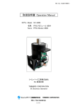
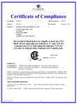
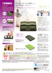
1
Ref. No. SCDD-090007
取扱説明書 Operation Manual
モデル Model: SC-UE15R
名称 Name: FPSC モジュール UE15R / 吸熱リング付
FPSC Module UE15 with Thermal Conductor
ツインバード工業株式会社 SC 事業本部
TWINBIRD CORPORATION SC Business Operation
TWINBIRD CORPORATION
(1/15)
http://fpsc.twinbird.jp
Ref. No. SCDD-090007
1. Field of Application and Restriction of Export
1. 適用分野と輸出規制について
The following regulations shall apply to Stirling Cooler and permission for export by
the Ministry of Economy, Trade and Industry is required before exporting Stirling
coolers from Japan for abroad.
・Foreign Exchange and Foreign Trade Law-section 1 of article 48.
・Foreign Exchange and Foreign Trade Law-section 1 of article 67.
・Export Trade Control Ordinance-section 2 of article 8.
輸出規制について
スターリング冷凍機は以下の日本の輸出規制と米国の再輸出規制が適用されます。
日本から輸出される場合は、経済産業大臣の許可が必要となります。
この場合は、米国の再輸出規制は適用除外になります。
輸出先から再輸出する際は、その国の輸出規制に従って下さい。
If you wish to export our Products from Japan for abroad, please contact us prior to
exporting.
該当項目:「光検出器の冷却器」
The above regulations were applied at the time of January 2008. Laws and
regulations may be revised according to the legal revisions.
<貨物>
輸出令別表1:10 項(2)号
貨物等省令:第9条1項六号ロ(一)
USA REEXPORT CONTROL, CCL; ECCN 6A002 d.2.a
"Cryocoolers for Optical sensors"
もし、輸出を希望する場合は、事前に弊社SC事業部にお問い合わせください。
なお、この適用は 2008 年 1 月現在であり、法令は改正されることがあります。
TWINBIRD CORPORATION
(2/15)
http://fpsc.twinbird.jp
Ref. No. SCDD-090007
2. 警告及び注意
2. Warning and Caution
(1) FPSC モジュール(Free Piston Stirling Cooler Module)は DC48V 専用です。DC12V、
(1) The Free Piston Stirling Cooler Module (FPSC Module) must be used with a 48 V
24V あるいは AC100~240V 等、他の電圧では使用しないでください。故障の原因とな
DC power source. Internal damage can result from operating this FPSC Module
directly with any input voltage other than 48 V DC.
ります。
(2) 0~40℃の環境でご使用ください。これ以外ですと、故障の原因となります。
(2) The FPSC Module is designed for use in ambient temperatures between 0 - 40 deg.
C.
Internal damage could result from operating the FPSC Module outside this
temperature range.
(3) 吸熱部の許容温度範囲は-120~+70℃です。冷えすぎないよう吸熱量を調節してくださ
い。また、ヒーターなどで加熱しないで下さい。故障の原因となります。
(3) The cold side of the FPSC Module should be maintained between -120 and +70 deg.
C. Operation outside of this temperature range could result in internal damage to the
FPSC Module. To avoid the possibility of damaging to internal parts by overheating
the FPSC.
Module, do not apply heating elements directly to the cold side.
(4) 放熱フィンが埃等により目詰まりしないようにご使用ください。
(4) Use caution to prevent the Heat Reject Fin from being filled by dust.
(5) 放熱フィンをお取り扱いの際は事故やけがにご注意ください。また、放熱フィンの変形、
破損にご注意ください。
(5) Use caution when handling the Heat Reject Fin assembly to prevent damage or
injury. Inspect the Heat Reject Fin assembly for deformity or breakage before use.
(6) FPSC モジュールから異音が発生したときは、出力設定電圧を調整して FPSC への出力
を抑えてください。
それでも異音が発生する場合は、弊社までお問い合わせください。
(6) Reduce the output setting of the FPSC Module if unusual noises are observed coming
from inside the pressure vessel.
Please contact Twinbird if the reduced output setting does not eliminate the unusual
noises.
(7) FPSC モジュールに強い衝撃を与えないで下さい。故障の原因となります。
(7) Avoid subjecting the FPSC Module to excessive shock. It could cause internal
damage.
(8) FPSC モジュールや基板に水等の液体をかけないでください。故障の原因となります。
(8) Direct exposure of the FPSC Module and PCB to water or other liquid could cause
electrical failure.
(9) 酸、アルカリ等の腐食性のガス及び液体、有害なガス雰囲気中及び有害なガスを発生
する物質のないところでご使用ください。錆が発生したり、寿命が短くなったりする場合
があります。
(9) Do not use the FPSC Module and the drive PCB in acidic, reactive gases or around
places that reactive gases are made. Rust or other corrosion may damage them
integrity and shorten the life span.
TWINBIRD CORPORATION
(3/15)
http://fpsc.twinbird.jp
(10) FPSC モジュールや基板をストーブや火気の近くに近づけないで下さい。故障の原因
となります。
Ref. No. SCDD-090007
(10) Direct exposure of the FPSC Module and PCB to fire or excessive heat could cause
internal damage.
(11) FPSC モジュールを火の中に放り込まないで下さい。内部のガスが膨張し、爆発する
恐れがあります。
(11) Warning: Placing the FPSC Module into fire or excessive heat could cause expansion
of the contained gas and explosion.
(12) コードを強く引っ張らないで下さい。断線し、故障の原因となります。
(12) Do not put excessive strain on the electrical cords. It could cause damage to the
wire and cause the FPSC Module stop operating.
(13) FPSC モジュールの分解は絶対に行わないでください。
(13) Do not disassemble the FPSC Module.
(14) FPSC モジュールの放熱フィンや基板の部品は、運転中及び停止直後は高温になって
いることがあります。素手で触わらないでください。火傷の恐れがあります。
(14) To avoid the danger of burns, avoid touching the heat reject fin and certain parts on
PCB with your bare hands during or immediately after operation.
(15) FPSC モジュールの吸熱部及びその周辺は、運転中及び停止直後は低温になってい
ます。素手で触わらないでください。凍傷の恐れがあります。
(15) To avoid the danger of frostbite, avoid touching the cold side and its immediate
surroundings with your bare hands during or immediately after operation.
(16) FPSC モジュールの吸熱部及びその周辺は、霜や露がつかないように断熱してくださ
い。また、単体での動作確認などで霜や露が付着した場合は、運転を停止させた後に
やわらかい布などでふき取ってください。着霜や結露は冷却能力の低下につながり、
融けた霜や露が電源コードや内部の機構部品に流れ落ちると、電気回路がショートし
て故障したり、腐食の原因になったりしますので、十分ご注意ください。
(16) Please provide thermal insulation around cold side to prevent frost and dew
condensation. If conditions require that you need to operate the FPSC Module
without thermal insulation, the cold side may develop a coating frost or water. If this
occurs, please clean the cold side with a soft cloth. Having frost or condensation on
the cold side surface can cause an apparent reduction of cooling capacity. Also, if
water drips down on a power cord or inner mechanical parts as it defrosts, it could
cause a short circuit or corrosion.
(17) FPSC モジュールの吸熱部は薄いステンレス板で形成されており、内部は精密構造に
なっておりますので、熱交換器の取り付けの際など、吸熱部に強い力を加えないで下
さい。故障の原因となります。
(17) Failure of the FPSC Module could result from subjecting the cold side to a strong
force. It is made of thin stainless steel sheet surrounding a precision structure.
(18) FPSC 内部に高圧のガスが封入されていますので、廃棄の際は弊社までご相談くださ
い。
(18) The Stirling cooler uses a high pressure gas inside, please contact Twinbird if you
intend to scrap the Stirling cooler.
TWINBIRD CORPORATION
(4/15)
http://fpsc.twinbird.jp
Ref. No. SCDD-090007
(19) Although the drive PCB is protected against reverse connection, use caution to
prevent static electricity or short circuit.
(A) Keep the PCB in the static shielding bag before use.
(B) Discharge static electricity from your body using wrist straps, etc.
(C) Electric parts may be damaged by the short circuit when the backside of the
PCB touches some metal parts.
It may be damaged by static electricity.
Use caution to prevent damage of backside electric parts.
(19) 駆動基板は電源の逆接続対策仕様で故障しにくくなっておりますが、静電気やショー
ト等に注意してお取り扱いください。
(A) 使わないときは、導電袋に入れておいて下さい。
(B) 基板を取り扱う際は、手首からアースを取る等、人体から静電気を放電することを
お勧めします。
(C) 裏面が金属に触れるとショートして電子部品が破損します。
電源が切れていても静電気等で故障する場合があります。
表面同様に裏面にも電子部品がついておりますので、ご注意下さい。
(20) 本製品の仕様を満足する範囲において、性能向上のため、部品など一部を連絡な
しに変更する場合があります。
(20) In order to improve the performance, the FPSC and associated parts may be
changed within the scope of the specification without any consultation or advice.
(21) 完成機器における規格、法令等の適合性については貴社にてご確認願います。
(21) Please ensure that local laws or standards are met for final products that are
equipped with this FPSC Module.
3. 仕様 Specification
3.1 外観 Exterior
[FPSC モジュール FPSC Module]
放熱フィン
Heat Reject Fin
吸熱部
Cold Side
[駆動基板 Drive PCB]
電源入力
Power Source Input
ブロア
Blower
FPSC 接続
FPSC
ブロアリード線
Blower Read Wire
サーミスタリード線
Thermistor Read Wire
FPSC リード線
FPSC Read Wire
TWINBIRD CORPORATION
(5/15)
http://fpsc.twinbird.jp
ブロア接続 排熱部サーミスタ接続
Blower
Warm Side Thermistor
Ref. No. SCDD-090007
3.2 主要寸法 Main Size
[FPSC モジュール FPSC Module]
13
[駆動基板 Drive PCB]
はんだ面高さ
Solder Side Height
146
⑥U字型溝ゴム U Shape Rubber
⑤M放熱フィン板 M Exhaust Fins Plate
0
部品面高さ
Parts Side Height
①150W型フリーピストンスターリングクーラー
150W Free Piston Stirling Coller
吸熱部 Cold Side
111
8
R4
FPSC全長 336
120
80
423
40
(79)
75
φ 58
.
φ 79 . 5
③Mマウント板
M Mount Plate
C8
2 8. 5
14 .5
7. 85
146
4 -M 5 φ 7
160
180
⑦放熱フィン Heat Reject Fin
②Mダクト M Duct
⑩サーミスタ
Thermistor
B lo w e r
E 12 3 2 L/ Ja p an Se r vo
32
⑪外部配線
Electric Wire
146
160
180
60.4
W in d
8-φ5.5取付穴 Hole for mount
58.6
⑧ブロア Blower
④Mファン板 M Fan Plate
65.9
51.1
[mm]
TWINBIRD CORPORATION
(6/15)
http://fpsc.twinbird.jp
Ref. No. SCDD-090007
3.3 主な仕様
No.
項 目
1
製品寸法
2
製品質量
3
冷媒
4
冷媒量
冷媒圧力
5
6
電源電圧※1
7
最大消費電流※1
8
冷凍能力※2
[条件]
周囲温度: 25℃
出力設定: 最大
使用温度・湿度条件※3
9
10
11
12
周囲温度
吸熱部温度
排熱部温度
湿度
3.3 Main Specification
No.
Item
1
Product Dimension
2
Weight
3
Refrigerant
4
Amount of Refrigerant
Inside Pressure of Stirling Cooler
5
6
Power Source Voltage*1
7
Maximum Current*1
8
Cooling Capacity*2
[Condition]
Ambient Temp.: 25℃
Output Setting: Max
Operating Conditions Ambient Temp.
9
of Temperature and Cold Side Temp.
10
Humidity*3
Warm Side Temp.
11
Humidity
12
仕 様
W 180 x H 159 x D 423 mm
約 9 kg
ヘリウム
約 3g
2.2 MPa (20℃)
DC 48 V ±10 % (駆動基板入力)
9A peak (48V 入力時)
120W±15%
(吸熱部温度: -23.3℃)
50W±15%
(吸熱部温度: -80℃)
0 ~ +40 ℃
-120 ~ +70 ℃
0 ~ +70 ℃
0 ~ 90 %RH
結露なきこと
駆動基板
Specification
W 180 x H 159 x D 423 mm
Approx. 9 kg
Helium
Approx. 3 g
2.2 MPa (20 deg. C)
DC 48 V ±10 % (for Drive PCB)
9A peak (at 24 V Input)
120W±15%
(Cold Side Temp.: -23.3 deg. C)
50W±15%
(Cold Side Temp.: -80 deg. C)
0 ~ +40 deg. C
-120 ~ +70 deg. C
0 ~ +70 deg. C
0 ~ 90 %RH
No Dew Condensation
Drive PCB
付属品
13
※1 動作確認済み電源
(1) TDK-Lambda ZWS240PAF-48/**
(トランス T1 コアの温度が 80℃以下になるよう、必要に応じて空冷する。)
(2) TDK-Lambda HWS300P-48
(カバー付タイプ)
Accessories
13
*1 Power Supplies tested with Drive PCB
(1) TDK-LAMBDA ZWS240PAF-48/**
(It must to keep the T1 trans core temperature lower than 80 deg. C. It may be
required to use air blow cooling.)
(2) TDK-Lambda HWS300P-48
(Covered type)
※2 冷凍能力は吸熱部温度、周囲温度などによって異なります。詳細につきましてはお問
い合わせください。
*2 Cooling capacity changes depends on the cold side temperature, ambient temperature,
etc. Please contact us for more information.
※3 (1) 吸熱部温度が 0℃を超えて使用する場合、応用製品に応じて FPSC への出力電圧
を絞ってご使用ください。
(2) 本製品を動作させたまま吸熱部温度を急激に変化させた場合、異常音が発生する
ことがあります。応用製品に応じて異常音が発生しないようにご使用ください。
*3 (1) If you use the cold side temperature over 0 deg. C condition, please turn the FPSC
voltage down accordingly the application product.
(2) An abnormal noise may occur from the FPSC when the cold side temperature is
changed suddenly. Please use accordingly the application product to prevent the
abnormal noise.
TWINBIRD CORPORATION
(7/15)
http://fpsc.twinbird.jp
Ref. No. SCDD-090007
4. 基本的な使い方
4.1 準備
(1)電源:電圧 DC48V、電流 9A peak
(2)温調器と温度センサー
(3)配線材とスイッチ
4. Basic Operation
4.1 Preparation
(1) Power source: Voltage DC48V, Output current: 9A peak
(2) Temp. controller and Temp. sensor
(3) Wire and Switch
4.2 起動手順
(1)DC48V 電源のスイッチを入れる。
(2)駆動基板に取り付けたスイッチを ON(CLOSE)にする。
4.2 Start Procedure
(1) Turn on the Switch of Power supply.
(2) Turn on the Switch of the Drive PCB.
4.3 停止手順
(1)駆動基板に取り付けたスイッチを OFF(OPEN)にする。
(2)DC48V 電源のスイッチを切る。
4.3 Stop Procedure
(1) Turn off the Switch of the Drive PCB.
(2) Turn off the Switch of Power supply.
4.4 配線 Wiring
[電圧入力の場合 Voltage Input]
[電流入力の場合 Current Input]
駆動基板 Drive PCB
温調器
Temp. Controller
+
(1~5V)
スイッチ
Switch
1
4
-
8
FPSC モジュール
FPSC Module
温度センサー
Temp. Sensor
-
2
3
-
CN7
4
スイッチ
Switch
CN2
FPSC モジュール
FPSC Module
サーミスタ
Thermistor
+
(4~20mA)
温度センサー
Temp. Sensor
8
DC48V 電源
DC48V Power Supply
CN1
-
TWINBIRD CORPORATION
(8/15)
CN2
CN6
ブロア
Blower
CN8
FPSC
+
CN7
サーミスタ
Thermistor
CN8
FPSC
DC48V 電源
DC48V Power Supply
+
CN6
ブロア
Blower
駆動基板 Drive PCB
温調器
Temp. Controller
+
-
+
CN1
-
http://fpsc.twinbird.jp
Ref. No. SCDD-090007
4.5 放熱
4.5 Heat Rejection
放熱フィンが埃等により目詰まりしないよう、フィルターを設置して目詰まりを防いだり、
Provide with some air intake filters or remove dust regularly on the heat reject fin to
定期的に放熱フィンに付着した埃を取り去ったりします。放熱フィンが目詰まりすると放熱
prevent the heat reject fin from being filled by dust. The dust filling reduces heat
が不足して冷却能力の低下や故障の原因になります。
rejection and cooling capacity and may cause damage of FPSC.
また、放熱、冷却能力向上のため、吸気はなるべく新鮮な空気を入れ、特に排気が回
In order to have better heat rejection and cooling capacity, get fresh air for the intake.
って来ないように、吸・排気経路の分離を行います。
In particular, separate the intake duct and exhaust duct to prevent the exhaust air
leakage to the intake.
4.6 断熱
4.6 Thermal Insulation
吸熱部と排熱部の間で、温度が周囲より低くなる部分(断熱部)を断熱材で覆い、霜や
Cover with the insulation material over the area the temperature can be lower than
露が着かないように断熱します。着霜や結露は冷却能力の低下につながり、融けた霜や
ambient between the cold side and the warm side, which is called Insulation Area, to
露がリード線や内部の機構部品に流れ落ちると、電気回路がショートして故障したり、腐
prevent having frost or condensation. Having frost or condensation on the Insulation
食の原因になったりします。
Area can cause an apparent reduction of cooling capacity. Also, if water drips down on a
断熱部は、使用状況により、吸熱部のすぐ近くだけの場合と、放熱フィンの近くまでの
read wire or inner mechanical parts as it defrosts, it could cause a short circuit or
場合があります。吸気を妨げないように注意します。
corrosion.
The Insulation Area may be closed to the cold side or up to near the heat reject fin
depend on the operation condition. The insulation must not inhibit the intake airflow.
ブロア
Blower
放熱フィン
Heat Reject Fin
排気
Exhaust Air
断熱部
Insulation Area
吸熱部
Cold Side
排気の回り込み防止
Exhaust Air Leak Prevention
吸気
Intake Air
TWINBIRD CORPORATION
(9/15)
http://fpsc.twinbird.jp
Ref. No. SCDD-090007
5. 駆動基板の入出力
5.1 一覧
Pin
仕様
[CN1] 吉田電機工業 PBX10C51-2
・端子ねじ: M3.5
・適正締付トルク: 0.8~1.2Nm
1
2
[CN2]
+ 電源入力
JST B2B-PH-K-E (青)
・適合コネクタ: JST PHR-2
1
排熱部サーミスタ
2
[CN6] JST B3B-EH (白)
・適合コネクタ: JST EHR-3
1
+ ブロア出力
2
3
空き(拘束センサー用)
[CN8] 吉田電機工業 PBX10C51-2
・端子ねじ: M3.5
・適正締付トルク: 0.8~1.2Nm
1
2
[SW1]
[SW2]
[SW3]
-
FPSC 出力
DIP SW
電圧変化速度設定
DIP SW
排熱部温度上限設定
DIP SW
電流制限値設定
Pin
仕様
[CN7] サトーパーツ ML-700-NV
・適合電線:
単線 φ0.32~0.65mm
(28~22 AWG)
より線 0.08~0.32mm2
(28~22 AWG)
(素線径φ0.12mm 以上)
・電線むき長さ: 9~10 mm
1
出力設定入力 1
2
+ 出力設定入力 2
3
4
運転/停止信号入力
5
異常信号出力
6
警告信号出力 1
7
警告信号出力 2
8
GND (信号側)
9
DC5V
[FG]
φ 1.8 mm (穴)
GND (電源側)
CN1
FG
CN8
5. Input and Output of Drive PCB
5.1 List
Pin
Specification
[CN1] YOSHIDA ELECTRIC INDUSTRY PBX10C51-2
- Screw: M3.5
- Proper Torque: 0.8~1.2Nm
1
2
[CN2]
+ Power Source Input
JST B2B-PH-K-E (Blue)
Acceptable Connector: JST PHR-2
1
Warm Side Thermistor
2
[CN6] JST B3B-EH (White)
Acceptable Connector: JST PHR-2
1
+ Output to Blower
2
3
NC
[CN8] YOSHIDA ELECTRIC INDUSTRY PBX10C51-2
- Screw: M3.5
- Proper Torque: 0.8~1.2Nm
1
2
CN6
Output to FPSC
CN2
CN7
Pin 9 ・・・・ 1
- +
Pin
Specification
[CN7] SATO PARTS ML-700-NV
-Acceptable Wire:
Solid wire φ0.32~0.65mm
(28~22 AWG)
Stranded wire 0.08~0.32mm2
(28~22 AWG)
(Element wire φ0.12mm Min)
-Strip Length: 9 - 10 mm
1
Setting of Output 1
2
+ Setting of Output 2
3
4
Drive / Stop of FPSC
5
Emergency Signal
6
Alarm Signal 1
7
Alarm Signal 2
8
GND (Signal Side)
9
DC5V
[FG]
φ 1.8 mm (Hole)
GND (Power Source Side)
[SW1] DIP SW
Setting of Output Voltage Change
[SW2] DIP SW
Setting of Warm Side Temperature Limit
[SW3] DIP SW
Setting of Output Current Limit
SW3
SW2
N7
SW1
TWINBIRD CORPORATION
(10/15)
http://fpsc.twinbird.jp
Ref. No. SCDD-090007
5.2 詳細
No.
5.2 Details
No.
仕 様
[CN1] 電源入力
Specification
[CN1] Power Source Input
1
定格電圧
DC 48 V
1
Rating voltage
2
許容電圧範囲
DC 43.2 ~ 52.8 V (DC 48 V ± 10 %)
2
Allowable voltage
DC 43.2 ~ 52.8 V (DC 48 V ± 10 %)
3
最大入力電流
9A peak (48V 入力時)
3
Maximum input current
9A peak (at 48V input)
[CN6] ブロア出力
DC 48 V
[CN6] Output to Blower
1
出力条件
FPSC 駆動時
1
Condition for output
While FPSC is driven
2
出力電圧
DC 12 V ±10%
2
Output voltage
DC 12 V ±10%
3
最大出力電流
2A
3
Output current capacity
[CN7] Pin1 出力設定入力 1
※1
[CN7] Pin1 Setting of Output 1
1
Step No.
2
入力電圧[V]
(CN7-Pin1)
0≦V<1
出力電圧 [V]
(CN8)
0
3
1
1
入力有効範囲
・・・
256
・・・
5
5<V<6
0
・・・
33.5
33.5/255(V/Step)
Available Input Range
1
・・・
256
1
Step No.
2
Input Voltage [V]
(CN7-Pin1)
4/255(V/Step)
0≦V<1
3
Output Voltage [V]
(CN8)
Input Circuit
33.5
入力回路
[CN7] Pin2,3 Setting of Output 2
※1
0
3
Step No.
入力電流[mA]
(CN7-Pin2,3)
出力電圧 [V]
(CN8)
0≦V<4
1
4
0
0
・・・
256
・・・
20
16/255(mA/Step)
・・・
33.5
33.5/255(V/Step)
・・・
5
4/255(V/Step)
0
・・・
33.5
33.5/255(V/Step)
5<V<6
33.5
*1
Available Input Range
入力有効範囲
1
2
1
Impedance: 200 kΩ
入力インピーダンス: 200 kΩ
[CN7] Pin2,3 出力設定入力 2
2A
*1
1
Step No.
1
20<I<21
2
33.5
3
Input Current [mA]
(CN7-Pin2,3)
Output Voltage [V]
(CN8)
0≦V<4
0
入力回路
Input Circuit
作動入力: 94 Ω
※1 電圧および電流が同時入力されている場合は、電圧入力が優先されます。
*1 Input voltage has priority over input current.
・・・
256
4
・・・
20
16/255(mA/Step)
0
・・・
33.5
20<I<21
33.5
33.5/255(V/Step)
Differential input impedance: 94 Ω
TWINBIRD CORPORATION
(11/15)
http://fpsc.twinbird.jp
Ref. No. SCDD-090007
No.
No.
仕 様
[CN7] Pin4 運転/停止信号入力
1
2
High (DC5V)
(Open)
Low (GND)
[CN7] Pin4 Drive / stop of FPSC
停止
1
運転
2
Vref
入力回路
Specification
High (DC5V)
(Open)
Low (GND)
Stop
Drive
Input Circuit
Vref
47kΩ
100Ω 1kΩ
47kΩ
IN
100Ω 1kΩ
Vref: DC5V (±10%)
[CN7] Pin5 異常信号出力
1
High
2
Low
IN
Vref: DC5V (±10%)
[CN7] Pin5 Emergency signal output
異常
FPSC 及びブロアへの電圧出力を停止する。
正常
1
High
2
Low
Emergency
Power supply to the FPSC and the blower will be stopped.
Normal
※異常の条件
(1) 排熱側温度センサーの温度が、SW2 で設定された排熱側温度上限に達した。
(2) 排熱側温度センサーが接続されていないか、又は、断線した。
(3) 入力電源電圧が範囲外である。
※異常信号出力停止条件
(1) 運転/停止信号が停止になった時
* Emergency situations
(1) Temperature sensor at warm side has reached the limit temperature set by SW2.
(2) Temperature sensor at warm side is disconnected or wire is cut.
(3) The power source voltage is out of allowable range.
*Condition for cancellation of the emergency signal output
(1) When the on / off signal goes off
出力回路
Output Circuit
項
出力
電圧
出力
電流
Vref: DC5V (±10%)
目
High
Low
High
Low
MIN.
Vref – 0.5V
8mA
-
TYP.
Vref
GND
10mA
10μA
MAX.
GND + 0.5V
12μA
条件
I=1mA
I=1mA
V=4.5V
V=0.5V
Item
Output High
Voltage Low
Output High
Current Low
MIN.
Vref – 0.5V
8mA
-
Vref: DC5V (±10%)
TWINBIRD CORPORATION
(12/15)
http://fpsc.twinbird.jp
TYP.
Vref
GND
10mA
10μA
MAX.
GND + 0.5V
12μA
Condition
I=1mA
I=1mA
V=4.5V
V=0.5V
Ref. No. SCDD-090007
No.
仕 様
No.
[CN7] Pin6 警告信号出力 1
1
High
警告
2
Low
正常
Specification
[CN7] Pin6 Alarm signal 1
※警告の条件
(1) 排熱部に設置した温度センサーの温度が、SW2 で設定された温度よりも 5℃低い温
度に達した。
※警告信号出力停止条件
(1) 警告の条件に該当しなくなった時。
[CN7] Pin7 警告信号出力 2
1
High
Alarm
2
Low
Normal
* Situation for alarm signal 1 output
(1) The temperature of the sensor on the warm side reaches 5 deg C lower than the
temperature set by SW2.
*Condition for cancellation of the emergency signal output
(1) When the temperature of the sensor on the warm side goes down 5 deg C lower than
the temperature set by SW1.
[CN7] Pin7 Alarm signal 2
1
High
警告
1
High
Alarm
2
Low
正常
2
Low
Normal
※警告の条件
(1) FPSC への出力設定信号のレベルが規定の範囲外である。
※警告信号出力停止条件
(1) 警告の条件に該当しなくなった時。
警告信号 1 及び警告信号 2 の出力回路
項 目
出力 High
電圧 Low
出力 High
電流 Low
MIN.
Vref – 0.5V
8mA
-
TYP.
Vref
GND
10mA
10μA
Vref: DC5V (±10%)
[CN8] FPSC への出力
* Situation for alarm signal 1 output
(1) The level of output set signal is out of the allowed range.
*Condition for cancellation of the emergency signal output
(1) When the level of output set signal is within the allowable range.
Output Circuit of Alarm signal 1 and Alarm signal 2
MAX.
GND + 0.5V
12μA
条件
I=1mA
I=1mA
V=4.5V
V=0.5V
Item
Output High
Voltage Low
Output High
Current Low
MIN.
Vref – 0.5V
8mA
-
TYP.
Vref
GND
10mA
10μA
MAX.
GND + 0.5V
12μA
Vref: DC5V (±10%)
[CN8] Output to FPSC
1
駆動波形
PWM 波形
1
Drive wave shape
PWM
2
基本周波数
80.0 Hz
2
Frequency
80.0 Hz
3
キャリア周波数
28.8 kHz
3
Carrier frequency
28.8 kHz
4
出力電圧範囲
AC 0~33.5 V (RMS) at 80.0Hz
4
Output voltage range
AC 0~33.5 V (RMS) at 80.0Hz
5
最大出力電流
9A (RMS)
5
Output current capacity
9A (RMS)
TWINBIRD CORPORATION
(13/15)
http://fpsc.twinbird.jp
Condition
I=1mA
I=1mA
V=4.5V
V=0.5V
Ref. No. SCDD-090007
No.
No.
仕 様
[SW1] 電圧変化速度設定
※3
Specification
[SW1] Setting of Output Voltage Change
Ramp time *1
SW1
0000
Change speed of
output voltage
Direct*2
-
23min48sec
0001
1 step /0.4 sec
1 step /6.4 sec
27min12sec
0010
1011
1 step /8.0 sec
34min00sec
6min48sec
1100
1 step /10.4 sec
1 step /2.4 sec
10min12sec
1101
0110
1 step /3.2 sec
13min36sec
0111
1 step /4.0 sec
17min00sec
SW1
電圧変化速度
0000
Direct※2
0001
上昇時間
※1
※1
SW1
*3
Ramp time *1
1000
Change speed of
output voltage
1 step /4.8 sec
1min42sec
1001
1 step /5.6 sec
23min48sec
1 step /0.8 sec
3min24sec
1010
1 step /6.4 sec
27min12sec
0011
1 step /1.2 sec
5min06sec
1011
1 step /8.0 sec
34min00sec
44min12sec
0100
1 step /1.6 sec
6min48sec
1100
1 step /10.4 sec
44min12sec
1 step /12.8 sec
54min24sec
0101
1 step /2.4 sec
10min12sec
1101
1 step /12.8 sec
54min24sec
1110
1 step /16.0 sec
1h08min00sec
0110
1 step /3.2 sec
13min36sec
1110
1 step /16.0 sec
1h08min00sec
1111
1 step /19.2 sec
1h21min36sec
0111
1 step /4.0 sec
17min00sec
1111
1 step /19.2 sec
1h21min36sec
SW1
電圧変化速度
上昇時間
-
1000
1 step /4.8 sec
20min24sec
1 step /0.4 sec
1min42sec
1001
1 step /5.6 sec
0010
1 step /0.8 sec
3min24sec
1010
0011
1 step /1.2 sec
5min06sec
0100
1 step /1.6 sec
0101
※1 0V から 33.5V に達するまでの時間。
※2 出力電圧は直接変わります。
急な設定変更はヒッティング(コンコンという衝突音)や不安定な動作の原因になりま
すので、十分ご注意ください。
ヒッティングの起こりやすい条件としては、「周囲温度が低い」、「吸熱部温度が
高い」、「動かし始め」等があります。また、定常状態になるまでの過渡状態に
ヒッティングが起こることがあります。過渡状態とは、FPSC 各部の温度が安定
するまでの間のことです。
ヒッティングを回避するためにも徐々に出力を増加させる必要があります。
※3 運転停止時の電圧変化速度: 10 step / 0.13 sec
[SW2] 排熱部温度上限設定
*1 The time from 0V to 33.5V
*2 Out voltage changes directly.
Sudden change of output setting could cause HITTING or unstable operation. Please
operate it much carefully. HITTING causes percussive noise.
HITTING may be caused in the following conditions, lower ambient temperature,
higher cold side temperature, just after startup, etc. It may be also caused in the
transient state, the state before the temperatures of all parts of FPSC become
stable.
It is necessary to ratchet up the output voltage to prevent the HITTING.
*3 Change speed of output voltage is fixed in process for stop: 10 step / 0.13 sec
[SW2] Setting of Warm Side Temperature Limit
SW2
排熱部温度上限
SW2
Warm Side Temperature Limit
1010
70℃
1010
70 deg. C
※この設定でご使用ください。
* Please use with this setting.
[SW3] 電流制限値設定
[SW3] Setting of Output Current Limit
SW3
電流制限値
SW3
Current Limit
1000
7.6A
1000
7.6A
※この設定でご使用ください。
20min24sec
* Please use with this setting.
TWINBIRD CORPORATION
(14/15)
http://fpsc.twinbird.jp
Ref. No. SCDD-090007
6. お問合せ先
6. Contact
ツインバード工業株式会社
SC 事業本部 SC 事業部
E-mail: [email protected]
Tel: 0256-92-6173
Fax: 0256-93-6168
〒959-0292 新潟県燕市吉田西太田 2084-2
TWINBIRD CORPORATION
SC Business Operation
E-mail: [email protected]
Phone: +81-256-92-6173
Facsimile: +81-256-93-6168
Address: 2084-2, Yoshida-nishiota, Tsubame-shi, Niigata-ken, 959-0292, Japan
TWINBIRD CORPORATION
(15/15)
http://fpsc.twinbird.jp