1
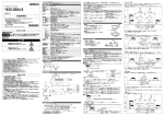
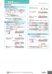
2. 各部の名称とはたらき
E2C-EDA□□
UP
DOWN
MODE
デジタルアンプ分離近接センサアンプユニット
SET
RUN
1
このたびは、本製品をお買い上げいただきまして、まことにありがとうございます。
ご使用に際しては、次の内容をお守りください。
・ 電気の知識を有する専門家がお取り扱いください。
・この取扱説明書をよくお読みになり、十分にご理解のうえ、正しくご使用ください。
・この取扱説明書はいつでも参照できるよう大切に保管してください。
FP
* 4 0 1 2 1 3 3 - 6 A *
(1/2)
安全上の要点
以下に示す項目は安全を確保するうえで必要なことですので必ず守ってください。
1)
引火性・爆発性ガスの環境では使用しないでください。
2)
水、油、化学薬品の飛沫のある場所、
蒸気のあたる場所では使用しないでください。
3)
製品の分解、修理・改造をしないでください。
4)
定格範囲を超える電圧、
電流を印加しないでください。
5)
電源の極性など、
誤配線をしないでください。
6)
負荷の接続を正しく行ってください。
7)
負荷の両端を短絡させないでください。
8)
ケースが破損した状態で使用しないでください。
9)
廃棄するときは、
産業廃棄物として処理してください。
使用上の注意
1)
電力線、動力線と本製品の配線は別配線としてください。同一配線あるいは同一ダクトにすると誘導
を受け、誤動作や破損の原因となることがあります。
2)
コードの延長は30m以下としてください。延長には0.3mm2以上のコードをご使用ください。
3)
電源投入後、200ms以上経過後に検出が可能となります。
負荷と本製品の電源が別の場合、
必ず本製品の電源を先に投入してください。
コード引き出しタイプにて連結使用時の場合は、電源を同時に入れてください。
連結されたセンサ間での電源投入時間差が30ms以上の場合は、
相互干渉防止機能が正常に動作しない、
またモバイルコンソールが
使用できない場合があります。
4)
保護カバーは必ず装着した状態で使用してください。
保護用シール
5)
コネクタタイプを使用される場合、感電や短絡防止のため、使用しない
連結用電源端子には保護用シール
(コネクタ:E3X-CNシリーズに付
連結用電源端子
属)
を貼ってください。
6)
通信ユニット接続専用タイプを使用される場合、感電や短絡防止のため、使用しない連結用端子に
は保護用キャップ
(通信ユニット:E3X-ECT/CRTに付属)
を付けてください。
7)
通信ユニット接続専用タイプの連結を着脱するときは、
連結部が斜めにならないようにしてください。
8)
センサヘッドのコネクタを着脱するときや、
アンプを着脱、増設するときは、
必ず電源を切ってください。
9)
電源遮断や静電気などのノイズにより書き込みエラーが発生
保護用キャップ
(ERR/EEPが点滅表示)
した場合、
体の設定キーによる設定
連結用端子
初期化処理を行ってください。
10)
モバイルコンソールで操作する場合
モバイルコンソール形E3X-MC11-SV2を使用してください。
形E3X-MC11、形E3X-MC11-Sは使用できません。
(通信ユニット接続専用タイプはモバイルコンソールが使用できません。)
11)
形E3X-DA-Nとは光通信できません。
12)
電源投入直後は使用環境に応じて検出量が安定するまで時間がかかる場合があります。
13)
電源遮断時に出力パルスが発生する場合がありますので、
負荷あるいは負荷ラインの電源を先行
て遮断してください。
14)
形E3C-LDAのセンサヘッドは使用できません。接続した場合、破損の可能性があります。
15)
相互干渉防止を有効にした場合、
ファインポジショニング実行時間が長くなります。
16)
清掃には、
シンナー、
ベンジン、
アセトン、灯油類は使用しないでください。
17)
断線検知出力機能は断線時以外で、検出量の大きい設置環境下で稀に出力することがあります。 設置時、断線検知の出力が出ていないことを確認のうえ、ご使用ください。
■パッケージ内容の確認
・アンプユニット
1台 ・取扱説明書(本書) 1部
1. 定格/性能
タイプ
高機能ツイン出力タイプ
高機能外部入力タイプ
通信ユニット
コード引き出しタイプ コネクタタイプ*1 コード引き出しタイプ コネクタタイプ*1 接続専用タイプ*3
接続方式
EDA11
EDA6
EDA21
EDA7
形式 (E2C-) NPN
EDA0
EDA41
EDA8
EDA51
EDA9
PNP
̶
DC12∼24V±10% リップル10%以下
電源電圧
消費電力1080mW以下
(24V時45mA)
消費電力
オープンコレクタ
(DC26.4V以下)
制御出力
̶
負荷電流:50mA以下、
残留電圧:1V以下
OFF/オフディレイ/オンディレイ/ワンショット
タイマ機能
1ms∼5s
タイマ時間
あり
微分検出モード
あり
ファインポジショニング機能
あり〈間欠発振方式〉*2 応答時間=(接続台数+1)×15ms
相互干渉防止機能
2∼5台
入出力設定
出力設定
(2CH出力/エリア出力
外部入力設定
(各種ティーチング 出力設定(2CH出力
/エリア出力
/自己診断出力/断線検知出力)
/ファインポジショニング
/自己診断出力
/ゼロリセット/同期検出)
/断線検知出力)
応答時間
「5.詳細設定」 検出機能参照
周囲温度
動作時:1∼2台連結時/−10∼55℃,
3∼5台連結時/−10∼50℃,
6∼16台連結時/−10∼45℃
17∼30台連結時
(EDA0をE3X-ECTと連結する場合)
/ー10∼40℃
但しEDR6-□と組み合わせ時:
3∼4台連結時/−10∼50℃,
5∼8台連結時/−10∼45℃,
9∼16台連結時/−10∼40℃
17∼30台連結時
(EDA0をE3X-ECTと連結する場合)
/ー10∼35℃
保存時:−20∼70℃
(ただし、
氷結、
結露しないこと)
周囲湿度
動作/保存時:35∼85%RH
(ただし、
結露しないこと)
振 動
10∼55Hz 複振幅1.5mm X,Y,Z方向 各2時間
*1:単品、親機でご使用の場合は E3X-CN21(親コネクタ 4 芯)、子機としてご使用の場合は E3X-CN22(子コネクタ 2 芯)
を別途お求めください。どちらのコネクタも使用できます。
*2:
「検出機能」に「SHS」を設定している場合は通信機能が無効となり、相互干渉防止機能および、モバイルコンソールとの
通信機能は使用できません。
*3:接続可能な通信ユニットは形E3X-ECT
(最大連結台数:30台)
と形E3X-CRT
(最大連結台数:16台)
です。各部の名称や設定については、
ツイン出力タイプの項目をご覧ください。
ボトムエラー
ファインポジショニング可能範囲に対して現在のワーク位置が近すぎた
ためのエラー。最小感度で調整されます。ファインポジショニング可能
範囲は、定格検出距離の約50%∼150%です。
2回点滅
FP
BOTM
タイムアウトエラー
ファインポジショニング実行中の検出量が安定しなかったためのエラー。
ワークとヘッドを確実に固定してから、再度ファインポジショニングを
実行してください。
2回点滅
FP
TOUT
■解除方法
RUNモードに切替
SET
MODEキーを押しながら、DOWNキーを3秒以上押す
注)MODEキーを押した後すぐにDOWNキーを押してください。
モードの切替
サブデジタルが2回点滅し、ファインポジショニングが解除されます。
モードの切替は
「SET/RUN切替スイッチ」
で行います。
目的にあったモードに切替えて操作してください。
モード
FP
内 容
SET
検出条件やティーチングによりしきい値を設定、
設定初期化するときに選びます。
RUN
実際に検出を行うときや以下の設定を行うときに選びます。
しきい値マニュアル調整、
位置決めティーチング、
ワークありなしティーチング、
ファインポジショニング、
ゼロリセット、
キーロックが選択できます。
RUNモード
UPキー
しきい値を上げます。
設定内容によってはたらきが変わります。
・ティーチングを実行
・設定値の変更
(順方向)
DOWNキー
しきい値を下げます。
設定内容によってはたらきが変わります。
・ティーチングを実行
・設定値の変更
(逆方向)
MODEキー
表示の見方
メインデジタル(赤色表示)
RUN※
サブデジタル(緑色表示)
キー操作によって検出量*や機能名称を順
番に表示します。
*
「検出機能」に
[DIFF]
(微分動作)
を設定
している場合でも検出量表示となります。
キー操作によってしきい値*やメインデジタルに
表示している機能の設定値を順番に表示します。
*
「検出機能」に[DIFF]
(微分動作)
を設定してい
る場合は検出量変化に対するしきい値を表示します。
現在の検出量を表示します。
(工場出荷時)
「検出機能」
に[DIFF]
(微分動作)
を設定
している場合は検出変化量を表示します。
現在のしきい値を表示します。(工場出荷時)「検
出機能」に[DIFF]
(微分動作)を設定している場
合は検出変化量に対するしきい値を表示します。
※表示内容は
「表示切替」機能で変更することができます。
「5.詳細設定」参照
4.基本設定
SETモード
に切替
SET
RUN
UPキーまたは
DOWNキーを
3秒以上押す
しきい値
設定された
しきい値が
2回点滅します。
RUNモード
に切替
検出時にONするか非検出時にONするかを選びます。
PPT
設定された
しきい値が
2回点滅します。
しきい値
「検出機能」に[DIFF]
(微分動作)を設定している場合、ワークありとワークなし
の2点の検出量の差の半分の値をしきい値とします。
■設定方法
【方法2】の場合は、あらかじめ[MODEキー設定]機能の設定が[2PNT](ワークあり
なしティーチング)になっていることを確認してください。
ワークなし
■設定方法
SETモードに切替
SET
形式
設定方法
ツイン出力タイプ
SETモードの「動作モード」で設定します。
「5.詳細設定」参照
外部入力タイプ
動作モード切替SWで選びます。
SETモード
に切替
RUN
ワークがある
状態でUPキー
またはDOWN
キーを押す
ワーク
サブデジタル
が点滅します。
TECH
----
NC
2 感度を調整する(必要に応じて)
一定時間で表示切替
現在検出中の検出量を「ファインポジショニング目標値(1500固定)」近くに調整した
いときに行う操作です。ファインポジショニングは必ず検出物体とヘッドを固定して、検
出量が安定している状態で実行してください。このとき、しきい値は1500になります。
検出量
SET
サブデジタルが点滅します。
TECH
---UPキーまたはDOWNキーを3秒以上押す。
このとき検出量と余裕度表示が表示されます。
設定されたしきい値が2回点滅します。
NEAR
しきい値
●設定エラー時
2回点滅
RUN
ワーク
TECH
サブデジタル
が点滅します。
----
ワークありの検出量
のばらつきに対する
現在の検出量の余
裕度を確認できます。
一定時間で表示切替
検出量
しきい値マニュアル設定
しきい値を手動で設定します。
RUNモードに切替
SET
検出量
RUN
しきい値
「表示切替」機能で設定されている内容が表示されます。
(工場出荷時設定は、検出量としきい値を表示)
UPキーまたはDOWNキーでしきい値を調整
しきい値が小さくなります。
UPキーまたはDOWNキーを押下してしきい値を変更している時は、
「表示切替」機能で設定されている内容にかかわらず、必ずサブデジタルに
デジタルしきい値が表示されます。しきい値変更終了後、約5秒で「表示切替」
機能で設定されている表示に戻ります。
4 基準値を登録する
(ゼロリセット)
基準値検出量「0」を登録し、基準に対するしきい値に対して検出を行います。
ワークの基準値の変化や使用環境による検出量の変化がある場合、ゼロリセット実行することに
より、より安定した検出ができます。
メインデジタルに表示されている検出量の表示を「0」にします。
サブデジタルの表示されているしきい値はシフトされません。
あらかじめ「MODEキー設定」機能の設定を[0RST](ゼロリセット)に変更しておいてください。
工場出荷時は[PPT](位置決めティーチング)が設定されています。「5.詳細設定」参照
「検出機能」
に
[DIFF](微分動作)を設定している場合はゼロリセット
できません。
ワーク通過順1
余裕度
ワークがない
状態でUPキー
またはDOWNキー
を押す
ワークがない
状態でMODEキー
を3秒以上押す
ワーク通過順2
再度
ゼロリセット実行
■設定方法
RUN
サブデジタルに進捗バーが
1桁ずつ表示されます。
進捗バー (進捗バーが表示されたら
キーを離します。)
ティーチングが完了し、操作前の表示に戻ります。
メインデジタルの表示について
FP
(ファインポジショニング実行中)
2PNT
一定時間で
表示切替
この段差を検出
この段差を検出
RUNモードに切替
MODEキーを3秒以上押す
OVER
次のどちらかを行った後、再度実行してください。
・検出量が小さくなるようにヘッド設定を調整する。
・ファインポジショニングを実行する。
しきい値が大きくなります。
RUNモード
に切替
ワークがある
状態でMODEキー
を3秒以上押す
ワークありの検出量
のばらつきに対する
現在の検出量の余
裕度を確認できます。
余裕度
■設定方法
あらかじめ、「MODEキー設定」機能の設定が[FP](ファインポジショニング)にな
っていることを確認してください。工場出荷時は、
[PPT](位置決めティーチング)
が設定されています。「5.詳細設定」参照
しきい値
ティーチングが完了し、
操作前の表示に戻ります。
設定された
しきい値が
2回点滅します。
2PNT
しきい値
設定された
しきい値が
2回点滅します。
ゼロリセット実行
■解除方法
RUNモードに切替
SET
RUN
MODEキーを3秒以上押す
検出量の表示変動が
止まります。
ティーチングが完了し、
操作前の表示に戻ります。
ファインポジショニング目標値
調整が完了し、操作前の表示に戻ります。
RUN
【方法2】
●設定方法は、アンプユニットのタイプによって異なります。
FP
センサヘッド
ワークありとワークなしの2点をそれぞれ検出し、その中間値の検出量をしきい値として設定します。
内 容
SET
ワークがない(背景)状態で設定します。
(ワークなし状態)検出量の約+6%をしきい値として設定します。
微妙な検出差を安定して検出できます。
■設定方法
②ワークありなしティーチング
SET
NO(ノーマリーオープン) 検出時に出力がONします。
(工場出荷時)
「検出機能」に[DIFF]
(微分動作)を設定している場合はエッジ検出
時出力がONします。
NC(ノーマリークローズ) 非検出時に出力がONします。
「検出機能」に[DIFF]
(微分動作)を設定している場合はエッジ検出
時出力がOFFします。
NO
LO
③ワークなしティーチング
MODEキーを
3秒以上押す
ティーチングが完了し、
操作前の表示に戻ります。
ティーチングが完了し、
操作前の表示に戻ります。
【方法1】
1 動作モードを設定する
選択肢
RUN
PPT
メインデジタルとサブデジタルに表示される内容は、現在選んでいるモードによって異な
ります。工場出荷後、初めて電源を入れるとRUNモードの内容が表示されます。
SET
SET
次のどちらかを行った後、再度実行してください。
・検出量が大きくなるようにヘッド設定を調整する。
・ファインポジショニングを実行する。
NEAR
※1 設定方法は
「4.基本設定」参照
モード
2PNT
【方法2】の場合は、あらかじめ[MODEキー設定]機能の設定が[PPT](位置決め
ティーチング)になっていることを確認して下さい。「5.詳細設定」参照
【方法1】
【方法2】
設定したい機能の表示を切り替えます。
「MODEキー設定」によってはたらきが
変わります。※1
・位置決めティーチング
(工場出荷時)
・ワークありなしティーチング
・ファインポジショニング実行
・ゼロリセット実行
OVER
2回点滅
UPキーまたはDOWNキーを押す。
■設定方法
SETモード
2PNT
次のどちらかを行った後、再度実行してください。
・検出量が小さくなるようにヘッド設定を調整する。
・ファインポジショニングを実行する。
ON点
「検出機能」に[DIFF](微分動作)を設定している場合、位置決めティーチ
ングはできません。
キーのはたらき
キーの種類
センサヘッド
位置決めしたい位置にワークがある状態で行います。
(ワークあり状態)
検出量をしきい値として設定します。
表示の切替や検出条件の設定操作は、操作キーで行います。
キーの役割は、現在選んでいるモードによって変わります。
2回点滅
OFF
3 しきい値を設定する
①位置決めティーチング
キー操作
●設定エラー時
ワークがない状態でUPキーまたはDOWNキーを押した後、以下の内容が表示された場合は、
エラー
が発生しています。
「検出機能」に[DIFF](微分動作)を設定している場合、(ワークなし状態の)
検出量の上側で安定して検出できる最小の位置にしきい値が設定されます。
RUN
+
3. 操作の基礎知識
© OMRON Corporation 2004 All Rights Reserved.
OVER
2
④サブデジタル(緑色表示)
⑥ツイン出力タイプ:チャンネル切替スイッチ
⑤SET/RUN切替スイッチ
外部入力タイプ:動作モード切替スイッチ
NO
NC
①出力がONしたときに点灯します。
ツイン出力タイプの場合、1CHの出力がONしたときに点灯します。
②検出量や機能の名称を表示します。
③ツイン出力タイプの場合、2CH側の出力がONしたときに点灯します。
外部入力タイプの場合、ファインポジショニングを設定すると点灯します。
④検出時の補助的な情報や機能の設定値を表示します。
⑤モードの切替を行います。
⑥ツイン出力タイプの場合、表示や設定を行うチャンネルを選択します。
外部入力タイプの場合、検出時にONするか非検出時にONするかを選びます。
⑦表示の切替や機能の設定操作を行います。
取扱説明書
オーバーエラー
ファインポジショニング可能範囲に対して現在のワーク位置が遠すぎた
ためのエラー。最大感度で調整されます。ファインポジショニング可能
範囲は、定格検出距離の約50%∼150%です。
2回点滅
⑦操作キー
E2C
形
●設定エラー時
進捗バー表示後、以下の内容が表示された場合は、エラーが発生しています。
②メインデジタル(赤色表示)
③ツイン出力タイプ:動作表示灯(2CH側)
①動作表示灯
外部入力タイプ:ファインポジショニング表示灯
検出量
ゼロリセットが
実行され、検出
しきい値 量の表示が「0」
になります。
RUNモードに切替
SET
RUN
+
MODEキーを押しながら、
DOWNキーを3秒以上押す
MODEキーを押した後すぐに
DOWNキーを押してください。
ゼロリセットが
解除されます。
検出量
しきい値
高速設定
応答時間300μs
以外
0RST
片側エッジ
立上がりまたは立下が
りエッジの一方を検出
RUNモードのときに表示させる内容を選びます。
SETモードに移行したときは、この設定に関わらず
「検出量としきい値」が表示されます。
5. 表示切替
検出比率
「微分エッジ選択」の設定によって
内容が変わります。
しきい値
2. タイマ機能
500μs
500μs
1ms
1ms
2ms
10ms
20ms
100ms
200ms
PEAK
ピーク検出量
O-PE
BOTM
C-BT
以外
ON-D
1SHT
検出状態
オフディレイタイマ
オンディレイタイマ
現在の検出量
ワンショットタイマ
PEAK
1∼20ms
1ms刻み
現在の検出量
2OUT
AREA
SELF
200ms∼1s
100ms刻み
1s∼5s
1s刻み
HEAD
チャンネルごとに出力
2つのしきい値間に検出量がある
場合にのみ出力
断線検知出力
ヘッド未接続または断線している
場合出力します。
NEAR
2PNT
D123
321D
7. 相互干渉防止
台数設定
ピーク検出量
AUTO
チャンネル
8. ヒステリシス
(応差)設定
ヒステリシス(応差)を設定します。
ワークのばたつきが大きい場合やよりシビアな
検出を行いたい場合に調整ください。
設定可能範囲:10∼2000
C
10
■取付け
センサヘッドコネクタ側のツメをレールにかけて、
フックがロックするまで押し込みます。
必ずセンサヘッドコネクタ側をレールにかけて
取付けてください。
逆に取付けると取付け強度が低下します。
ON
OFF
実行結果をEEPROMに書込む
実行結果をEEPROMに書込まない
19
3.9×4=11.7
50.3
76
8.1
(コード引き出しタイプ)
DINレール
24.7
36.7
1
2
■取外し
1の方向に押しつけたままセンサヘッドコネクタ側
を2の方向へ持ち上げます。
ご使用に際してのご承諾事項
DINレール
■連結して使用する場合
(コネクタタイプ/通信ユニット接続専用タイプの場合)
コネクタタイプは16台まで連結することができます。通信ユニット接続専用タイプは通信ユニット形
E3X-ECTと接続する場合は30台まで、形E3X-CRTと接続する場合は16台まで連結することができ
ます。
1.アンプユニットをそれぞれDINレールに取付けます。
2.アンプユニットをスライドさせ、
カチッと音がするまでコネクタを差し込みます。
振動などで連結部が離れる場合は、別売のエンドプレート(形PFP-M)で固定してください。
取外しは逆の順番で行ってください。
必ずアンプユニットの連結を外してからDINレールから取外してください。
2
1
①安全を確保する目的で直接的または間接的に人体を検出する用途に、本製品を使用
しないでください。同用途には、当社センサカタログに掲載している安全センサをご使用
ください。
②下記用途に使用される場合、当社営業担当者までご相談のうえ仕様書などによりご確
認いただくとともに、定格・性能に対し余裕を持った使い方や、万一故障があっても危
険を最小にする安全回路などの安全対策を講じてください。
a)屋外の用途、潜在的な化学的汚染あるいは電気的妨害を被る用途
またはカタログ、取扱説明書等に記載のない条件や環境での使用
b)原子力制御設備、焼却設備、鉄道・航空・車両設備、
医用機械、
娯楽機械、
安全装置、
および行政機関や個別業界の規制に従う設備
c)人命や財産に危険が及びうるシステム・機械・装置
d)ガス、水道、電気の供給システムや24時間連続運転システムなどの
高い信頼性が必要な設備
e)その他、上記 a) ∼ d) に準ずる、高度な安全性が必要とされる用途
*上記は適合用途の条件の一部です。当社のベスト、総合カタログ・データシート等最新版
のカタログ、
マニュアルに記載の保証・免責事項の内容をよく読んでご使用ください。
インダストリアルオートメーションビジネスカンパニー ●お問い合わせ先
カスタマサポートセンタ
フリーコール
8.センサヘッドの接続
1.保護カバーを開けます
2.センサヘッドのコネクタ部のロックレバーが上になるように向け、
コネクタ挿入口に奥まで 差し込
みます。
取外しは、
ロックレバーを押しながら、
引き抜いてください。
1
ロックレバー
2
外部入力の実行結果をEEPROMに書込むかどうかを
選びます。
外部入力を頻繁に行う場合は、設定をOFFにしてく
ださい。(書込み可能回数:約10万回)
(単位:mm)
2.5
7.アンプユニットの設置
ツイン出力タイプの場合は各チャンネルごとに設定できます。
(外部入力タイプのみ表示)
青
GOOD
上下反転
ワークなしティーチング
オートマチックティーチング
入力がONしている間の最大検出量と最小検
出量をサンプリングし、OFFした時点で最大
値と最小値の中間にしきい値を設定します。
「検出機能」に[DIFF](微分動作)を設定
している場合は無効となります。
INIT
通常表示
相互干渉防止機能は機能しません。
DC
12∼24V
初期化する
相互干渉防止台数を設定します。相互干渉を防止さ
せたい台数のみアンプを連結させ、連結させている
アンプすべてに設定してください。
設定後、必ず電源再投入してください。
設定可能範囲:2[2UT]∼5[5UT]
OFF
9. 外部入力メモリ
YES?
初期化しない
1
位置決めティーチング
ワークありなしティーチング
NO?
NO?
YES?表示時にMODEキーを押す
6. 表示方向
(外部入力タイプのみ表示) 外部装置から設定可能とする内容を選びます。
PPT
A
検出量
自己診断出力
検出量が不安定状態の時
(約300mS以上しきい値約±10%
になったとき)に検出します
1チャンネルは「検出機能」で選択されたモード
で動作します。
B
現在の検出量とピーク
時の検出量
検出量とチャンネル番号
2チャンネルの出力内容を選びます。
(ツイン出力タイプのみ表示) 「検出機能」に[DIFF]
(微分動作)を設定している
場合、この設定内容は無効となります。
(必ずアラーム出力となります)
3. 外部入力
アナログバー表示
現在の検出状態をバー
表示します。
ワークが近づくに
つれて右側からバーが
点灯していきます。
一定時間で表示切替
20ms∼200ms 5ms刻み
3. ツイン出力
検出時のピーク検出量と
非検出時のボトム検出量
検出時、非検出時に表示
が切り替わります。
外部入力
(通信ユニット接続専用タイプ)
38.8
35.8
3.9×4=11.7
21.1
18.15
センサヘッドコネクタ側のツメ
設定可能範囲:1∼5000
タイマ時間
UPキーと
DOWNキーを
同時に3秒以上押す
ボトム検出量
タイマ機能無効
OFFD
一定時間
(2S)
のピーク
検出量とボトム検出量
一定時間で表示切替
ツイン出力タイプの場合は各チャンネルごとに設定できます。
----
検出比率としきい値
検出比率:しきい値に
対する検出量の比率(%)
外部入力
黒 制御出力
初期化が完了しました。
しきい値
片側エッジ 両側エッジ
300μs
INIT
検出量としきい値
検出量
両側エッジ
立上がりと立下がり
エッジの両方を検出
微分応答時間
+
ゼロリセット実行
橙
31
HS
FP
橙
DC
12∼24V
12.50
最速設定
応答時間150μs
ファインポジショニング実行
黒 制御出力
10.外形寸法図
SETモードに切替
RUN
茶
茶
*形E2C-EDA0は通信ユニット接続専用タイプです。
設定内容をすべて初期化し、工場出荷時の状態に戻します。
■設定方法
SET
■形E2C-EDA51、形E2C-EDA9(PNPタイプ)
青
設定データを初期化する(設定初期化処理)
ワークありなしティーチング実行
■形E2C-EDA21、形E2C-EDA7(NPNタイプ)
32
SHS
2PNT
DC
12∼24V
青
14
PPT
微分動作設定
検出量の変化率に応じて動作
ツイン出力タイプの場合、2チャンネ
ルは絶対検出量に対する出力(アラー
ム出力)となります。
位置決めティーチング実行
青
32
微分エッジ選択
RUNモードのときのMODEキーの役割を選びます。
OFF
橙 2CH出力
負荷
高精度設定
応答時間4ms
LOC
黒 1CH出力
負荷
HRES
ON
サブデジタルが2回
点滅し、キー入力が
できるようになり
ます。
キーロック中にキー入力した場合
キーロック中に解除以外のキーを入力した場合、
[LOC]が2回点滅し、キーロックであることを知らせます。
検出開始時間
500μs以上
4. MODEキー設定
サブデジタルが2回
点滅し、キー入力が
無効になります。
DC
12∼24V
内部回路
STND
標準設定
応答時間1ms
DIFF
LOC
ON有効パルス幅
0.1s以上
非検出時ON
NC
1. 検出機能
(実行)0.1s∼2s
(解除)3s以上
MODEキーを押しながら、
UPキーを3秒以上押す
MODEキーを押した後すぐに
UPキーを押してください。
+
橙 2CH出力
内部回路
NO
パルス幅
0.1s∼2s
,
検出時ON
MODEキーを押しながら、
UPキーを3秒以上押す
MODEキーを押した後すぐに
UPキーを押してください。
+
RUN
負荷
(ツイン出力タイプのみ表示)
0. 動作モード
,
チャンネルごとに設定できます。
SET
負荷
一定時間で表示切替
有効パルス幅について
選択肢
RUNモードに切替
RUN
茶
内部回路
SYNC
※1:ティーチングの設定方法は「4.基本設定」を参照
SET
黒 1CH出力
負荷
(検出量/しきい値を表示)
RUNモードに切替
同期検出
外部入力有効の場合のみ検出を行います。
■形E2C-EDA41、形E2C-EDA8(PNPタイプ)
茶
負荷
ティーチング
■解除方法
■形E2C-EDA11、形E2C-EDA6(NPNタイプ)
内部回路
0RST
キー操作をすべて無効にします。キーの誤操作を防止するのに役立ちます。
無効にできるのは操作キーのみです。各切替えスイッチは無効になりません。
■設定方法
ゼロリセット
RUN
9.入出力段回路図
キーロック
ファインポジショニング
FP
SETモードに切替えます
SET
6.便利な機能
C
9.9
B
3.4
A
13.8
5.詳細設定
SETモードでは以下の機能設定ができます。
機能遷移に表示している内容は、工場出荷時の内容です。
ツイン出力タイプの場合、「動作モード」と「タイマ」、「ヒステリシス設定」以外はチャンネル共
通の設定となります。
*:しきい値、検出量、比率など数値の表示内容は一例であり、実際の表示とは異なります。
01 2 0 - 9 19 - 0 6 6
携帯電話・PHSなどではご利用いただけませんので、
その場合は下記電話番号へおかけください。
電話
055-982-5015 (通話料がかかります)
〔技術のお問い合わせ時間〕
■営業時間:8:00∼21:00
■営 業 日:365日
■上記フリ−コ−ル以外のセンシング機器の技術窓口:
電話
055-982-5002
(通話料がかかります)
〔営業のお問い合わせ時間〕
■営業時間:9:00∼12:00/13:00∼17:30 (土・日・祝祭日は休業)
■営 業 日:土・日・祝祭日/春期・夏期・年末年始休暇を除く
●FAXによるお問い合わせは下記をご利用ください。
カスタマサポートセンタ お客様相談室 FAX 055-982-5051
●その他のお問い合わせ先
納期・価格・修理・サンプル・仕様書は貴社のお取引先、
または貴社担当オムロン営業員にご相談ください。
A q 2009年10月
E2C-EDA□□
②Main display (red)
①Operation indicator
* 4 0 1 2 1 3 3 - 6 A *
(2/2)
PRECAUTIONS FOR SAFE USE
PRECAUTIONS FOR CORRECT USE
Please observe the following precautions to prevent failure to operate, malfunction, or undesirable
effects on product performance.
1) Wire the Amplifier Unit separately from power supply or high-voltage lines. If the Amplifier Unit
wiring is wired together with or placed in the same duct as high-power lines, inductive noise may
cause operating errors or damage the Amplifier Unit.
2) Do not extend the cable to more than 30 m, and use a wire size of 0.3 mm2 or larger for the extension cable.
3) The Amplifier Unit is ready to operate 200 ms after the power supply is turned ON. If the Amplifier Unit and load are
connected to power supplies separately, turn ON the power supply to the Amplifier Unit first.
Please turn on the power supply at the same time when you connecting use the Amplifier Units with cables.
Mutual interference prevention might not operate normally or mobile console might not be able to be used
when the difference between connected Amplifiers at the power supply turning or time is 30ms or more.
4) Always keep the protective cover in place when using the Amplifier Unit.
5) When using a connector model, place a protective label (provided with the E3X-CN series connectors) on
Protector seal
the power supply connecting terminals that are not used, to prevent electric shock or short circuit.
Power supply
6) When using a communication unit connection model, place a protective cap
connector
(provided with the E3X-ECT/CRT communication unit ) on the connecting
terminals that are not used, to prevent electric shock or short circuit.
7) When connecting or removing the communication unit connection
model, make sure that the connecting part is not slanted.
8) Always turn OFF the power supply before connecting or disconnecting Sensor
Heads, joining or separating Amplifier Units, or adding Amplifier Units.
9) If the data is not written to the EEPROM correctly due to a power failure or
Protective Cap
static-electric noise, initialize the settings using the keys on the Amplifier Unit.
Power Supply
10) Using a Mobile Console (The communication unit connection
Connecting Terminal
model cannot use a mobile console.)
Use the E3X-MC11-SV2 Mobile Console for the E2C-EDA-series Amplifier Units. Other Mobile
Consoles, such as the E3X-MC11,E3X-MC11-S, cannot be used.
11) Optical communications are not possible with an E3X-DA-N Amplifier Unit.
12) Depending on the application environment, time may be required for the detection level to stabilize after the power supply is turned ON.
13) Output pulses may occur when the power is interrupted and so turn OFF the power to the load or
load line before turning OFF the power to the Sensor.
14) The Sensor Head of E3C-LDA cannot be used. It may damage, if it connects.
15) When mutual interference prevention is confirmed, the execution time of fine positioning becomes long.
16) Do not use thinners, benzine, acetone, or kerosene for cleaning the Amplifier Unit.
17) A disconnection output may be rarely outputted under the large installation conditions of a detection level also except disconnection.
■ Confirming the Package Contents
・Amplifier Unit: 1 ・Instruction Sheet (this sheet): 1
1. Ratings and Specifications
Response time
Operation
Ambient
temperature
Storage
Ambient humidity
Vibration
⑤SET/RUN switch
RUN
1
FP
⑦Operation keys
OVER
Flashes twice
2
⑥Twin-output Models : Channel selector
NO
NC
Lit when the output is ON.
Twin-output Models: Lit when the output for channel 1 is ON.
Displays the detection level or the function name.
Twin-output Models: Lit when the output for channel 2 is ON.
External-input Models: Lit when fine positioning is set.
Displays supplemental detection information, the setting of a function, etc.
Used to switch the mode.
Twin-output Models: Used to select the channel to display or set.
External-input Models: Used to select normally-open or normally-close operation
Used to change the display, set functions, etc.
FP
BOTM
FP
Advanced, twin-output models Advanced, external-input models Communication unit
Prewired
Separate
Prewired
Separate
connection model *3
connector*1
connector*1
E2C-EDA0
E2C-EDA11
E2C-EDA6
E2C-EDA21
E2C-EDA7
E2C-EDA41
E2C-EDA8
E2C-EDA51
E2C-EDA9
ー
12 to 24 VDC±10% ripple(p-p) 10%max.
1,080mW max. (45mA max. at 24 VDC)
Open collector (26.4 VDC max.);
ー
Load current: 50mA max.; residual voltage: 1 V max.
OFF, OFF-delay, or one-shot
1 ms to 5 s
Supported
Supported
Supported (intermittent oscillation system)*2
response time = (number of Amplifier Units + 1)×15 ms
The number of setting : 2 to 5
Output setting (channel 2 output,
External input setting (teaching
Output setting
area output, self diagnosis output, method, fine positioning, zero reset, (2CH output)/area output
or disconnection output)
or synchronous detection)
/self-diagnosis output)
Refer to 5.Detailed Settings Detection Method
Groups of 1 to 2 Amplifiers: -10℃to 55℃ Groups of 3 to 5 Amplifiers: -10℃ to 50℃
Groups of 6 to 16 Amplifiers: -10℃ to 45℃ Groups of 17 to 30 Amplifiers: −10°C to 40°C
Combination with EDR6-□
Groups of 3 to 4 Amplifiers: -10℃ to 50℃ Groups of 5 to 8 Amplifiers: -10℃ to 45℃
Groups of 9 to 16 Amplifiers: -10℃ to 40℃ Groups of 17 to 30 Amplifiers: −10°C to 35°C
−20℃ to 70℃ (with no icing or condensation)
Operation/Storage: 35 to 85 %RH (with no condensation)
10 to 55 Hz, 1.5mm double amplitude 2 hours each in X, Y, and Z directions
*1: When using individually or as a master, obtain the E3X-CN21 Master Connector (4-conductor), and when
using as a slave, obtain the E3X-CN22 Slave Connector (2-conductor). Either Connector can be used.
*2: Communications are disabled if SHS is selected for the detection mode, and the communications functions
for mutual interference prevention and the Mobile Console will not function.
*3: Connectable communication units are E3X-ECT (30 units max.) and E3X-CRT (16 units max.). For details
on names of each part and settings, refer to items of the twin output model.
Timeout Error
An error occurred because the detection level was not stable during fine
positioning.
Make sure that the workpiece and Sensor Head are secured and retune
the sensitivity.
TOUT
●Clearing method
RUN
Setting the Mode
The mode is set using the SET/RUN switch. Set this switch according to the operation to be performed.
Description
Select to set detection conditions, to teach the threshold value, to set initializing, etc.
RUN
Select for actual detection operation or set the following: Manual adjustment of
thresholds, Positioning teaching, Teaching with and without a workpiece, Fine
positioning, Zero reset, or Key lock
Key Operations
Function
UP key
DOWN key
MODE key
RUN mode
SET mode
Increases the threshold.
Depends on the setting.
・Executes teaching.
・Changes the setting forward.
Decreases the threshold.
Depends on the setting.
・Executes teaching.
・Changes the setting in reverse.
Depends in the MODE key setting (See note.)
・Executes positioning teaching(default setting).
・Teaching with and without a workpiece.
・Executes fine positioning.
・Executes a zero reset.
FP
OFF
3 Setting Thresholds
①Positioning Teaching
Main display (red)
Mode
Sub-display (green)
Displays the detection level,* function name,
or other information depending on the key
operation.
*The detection level will be displayed even if
DIFF (differential operation) is set for the
detection method.
Displays threshold value* or the setting of the
function displayed on the main display depending
on the key operation.
*The threshold value for the change in the
detection level will be displayed if DIFF (differential
operation) is set for the detection method.
For the default setting, the current threshold
For the default setting, the current
RUN
value
will be displayed.
(See note.) detection level will be displayed.
The threshold value for the change in the
The change in the detection level will be detection level will be displayed if DIFF
displayed when DIFF (differential
(differential operation) is set for the detection
operation) is set for the detection mode. method.
SET
Note: The information that appears on the displays can be set using the display switch
function. Refer to 5. Detailed Settings.
4. Basic Settings
1 Setting the Operation Mode
Set as the operation mode in SET mode.
Refer to 5. Detailed Settings.
External-input model
Set using the operation mode selector.
NO
【Method 1】
SET
Switch to SET
mode.
RUN
SET
RUN
Press the UP or DOWN
key for at least 3 seconds.
PPT
Threshold
value
Switch to RUN
mode.
The threshold
value that was set
will flash twice.
PPT
Threshold
value
The threshold
value that was set
will flash twice.
If DIFF (differential operation) is set for the detection method, the threshold value
will be set to half of the difference between the two measured values.
In the case of a 【Method 2】, please check that a setup of a "MODE key setting" function is
[2PNT](teaching with and without a workpiece) in advance. Refer to 5.Detailed Settings.
【Method 1】
Switch to SET
mode.
RUN
RUN
Detection
level
SET
RUN
Position a workpiece
and press the MODE
key for at least 3
seconds.
The sub-display will
flash.
TECH
---A detection margin
level can check the
margin of the present
detection level to the
variation in a detection
level with a workpiece.
Detection
margin value
Main Display
2PNT
Detection
level
Threshold
value
----
Display alternates
at a fixed interval.
Detection
level
Threshold
value
Teaching completed and
previous display returns.
The threshold
value that was set
will flash twice.
A detection margin
level can check the
margin of the present
detection level to the
variation in a detection
level with a workpiece.
Decreases the threshold value.
When the UP or DOWN key is pressed to change the threshold value, the threshold
value will be displayed on the sub-display regardless of the display switch setting.
The information set for the display switch setting will return approximately 5 seconds
after the threshold is changed.
5 A zero point is registered. (zero reset)
The standard position of a workpiece is registered as "detection level =0", and it judges to the amount of
change of a detection level. When there is change of the standard position of a workpiece or change of
the detection level by the operating condition, detection stabilized when performing zero reset can be
performed.
Execution of zero reset shifts to "0" the detection level currently displayed on the main display. The
threshold value currently displayed on the sub display is not shifted.
Please set "a MODE key settings" as "0RST" in advance. The default is "PPT" (positioning teaching).
Refer to 5.Detailed Settings.
Zero reset cannot be performed when DIFF(differential operation) is set as the
detection method.
Workpiece
Next workpiece
Detection
margin value
Threshold
value
This level difference
is judged.
This level difference
is judged.
Remove the
workpiece and
press the MODE
key for at least 3
seconds.
2PNT
The information set for the display switch will be displayed.
(The default setting is for the detection level and the threshold value.)
Increases the threshold value.
Switch to RUN
mode
Workpiece
Switch to RUN mode.
Tuning completed and previous display returns.
Switch to RUN mode.
SET
Adjust the threshold value with the UP and DOWN keys.
Position a workpiece
and press the
UP or DOWN key.
Workpiece
OVER
●Setting method
【Method 2】
Remove the
workpipece and
press the UP or
DOWN key.
Fine positioning target value
NEAR
Do one of the following and then repeat the operation
・Adjust the Head to decrease the detection level.
・Execute fine positioning.
Teaching completed and previous display returns.
●Setting method
●Setting method
Display alternates
at a fixed interval.
●Setting Errors
Flashes twice
A threshold value can be set manually.
Teaching can be performed twice, once with and once without a workpiece, and the value between
the two measured values is set as the threshold.
Display alternates
at a fixed interval.
FP
During fine
positioning
The threshold value that was set will flash twice.
Threshold
value
4 Manually Setting Threshold Values
Teaching completed and
previous display returns.
②Teaching With and Without a Workpiece
Confirm that the MODE key setting is FP(fine positioning) in advance.
The default is "PPT" (positioning teaching). Refer to 5. Detailed Settings.
A progress bar will appear
on the sub-display one
FP Progress bar digit at a time.(Release the
MODE key when the
progress bar appears.)
Press the UP or DOWN key for at least 3 seconds.
A detection level and a detection margin value are displayed.
Press the MODE key for
at least 3 seconds.
Teaching completed and
previous display returns.
NC
RUN
Press the MODE key for at
least 3 seconds.
The sub-display will flash.
----
【Method 2】
2 Adjusting the sensitivity (as Required)
SET
Press the UP or DOWN key.
NEAR
TECH
Fine positioning can be used to adjust the detection level that is currently being received to the fine
positioning target value (1,500). Before executes fine positioning, always secure the workpiece and
Sensor Head and be sure that the detection level is stable.
Switch to SET mode.
RUN
In the case of a【Method 2】, please check that a setup of a "MODE key setting" function is
[PPT](positioning teaching) in advance. Refer to 5.Detailed Settings.
The sub-display
will flash.
Twin-output model
●Setting method
TECH
●The setting method depends on the type of Amplifier Unit.
Setting method
Sensor head
ON point
Select either normally-open or normally-close operation.
Type
LO
Teaching is performed in the state where there is no workpiece.
It sets up about +6% of a detection level as a threshold value. It is stabilized and a very small
difference can be detected.
SET
●Setting method
SET
Selection
Description
NO(normally-open) The output will turn ON when the detection level is above the threshold.
(default)
If DIFF (differential operation) is set for the detection method, the output will turn
ON when an edge is detected.
NC(normally-close) The output will turn ON when the detection level is below the threshold.
If DIFF (differential operation) is set for the detection method, the output will turn
OFF when an edge is detected.
2PNT
Do one of the following and then repeat the operation
・Adjust the Head to increase the detection level.
・Execute fine positioning.
③No-workpiece Teaching
Teaching cannot be performed when DIFF(differential operation) is set as the detection
method.
Note: Refer to 4.Basic settings for the setting method.
Reading Displays
2PNT
OVER
Flashes twice
Sensor head
Teaching is performed in the state where a workpiece is in an ON
point. A detection level is set up as a threshold value.
Switches the function to be set on the
display.
The information displayed on the main display and sub-display depends on the current mode. For the
default settings, the RUN mode displays will appear when the power supply is turned ON for the first time.
Do one of the following and then repeat the operation
・Adjust the Head to decrease the detection level.
・Execute fine positioning.
Without a workpiece
The sub-display will flash twice and fine positioning will be cleared.
The operation keys are used to switch the displays and set detection conditions. The functions of the
keys depend on the current mode.
Key
Flashes twice
Hold down the MODE key and press the DOWN key for at least 3 seconds.
Note: Press the DOWN key right after pressing the MODE key.
+
Mode
SET
An error has occurred if any of the following is display when the UP or DOWN key is pressed
without a workpiece.
If DIFF(differential operation) is set for the detection method, the threshold value will be set
to the minimum value above the detection level without a workpiece that will enable stable
detection.
Switch to RUN mode
SET
●Setting Errors
Bottom Error
It is the error for the present workpiece position having been too near to the
fine positioning possible range. It is adjusted by the minimum sensitivity. The
fine positioning possible range is 50 to 150% of measurement range.
Flashes twice
3. Basic Operating Information
Please observe the following precautions for safe use of the product.
1) Do not use the Amplifier Unit in environments subject to flammable or explosive gases.
2) Do not use the Amplifier Unit in environments subject to exposure to water, oil, chemicals, etc.
3) Do not attempt to disassemble, repair, or modify the Amplifier Unit in any way.
4) Do not apply voltages or currents that exceed the rated ranges.
5) Wire the Amplifier Unit correctly, e.g., do not reverse the polarity of the power supply.
6) Connect the load correctly.
7) Do not short both ends of the load.
8) Do not use the Amplifier Unit if the case is damaged.
9) When disposing of the Amplifier Unit, treat it as industrial waste.
I/O settings
MODE
Over Error
It is the error for the present workpiece position having been too far to the
fine positioning possible range. It is adjusted by the maximum sensitivity.
The fine positioning possible range is 50 to 150% of measurement range.
Flashes twice
External-input Models : Operation mode selector
①
②
③
④
⑤
⑥
⑦
Manufacturer:
Omron Corporation,
Shiokoji Horikawa, Shimogyo-ku,
Kyoto 600-8530 JAPAN
Ayabe Factory
3-2 Narutani, Nakayama-cho,
Ayabe-shi, Kyoto 623-0105 JAPAN
The following notice applies only to products that carry the CE mark:
Notice:
This is a class A product. In residential areas it may cause radio
interference, in which case the user may be required to take adequate
measures to reduce interference.
Timer
Timer time
Differential detection mode
Fine positioning
Mutual interference
prevention
DOWN
E2C
④Sub-display (green)
TRACEABILITY INFORMATION:
Representative in EU:
Omron Europe B.V.
Wegalaan 67-69
2132 JD Hoofddorp,
The Netherlands
Model
NPN
number
PNP
Supply voltage
Power consumption
Control output
An error has occurred if one of the following display appears the progress bar is displayed.
External-input Models : Fine positioning indicator
SET
INSTRUCTION SHEET
Type
Connection method
③Twin-output Models : Operation indicator for channel 2
UP
Proximity Sensors with Separate Digital Amplifier
Amplifier Units
© OMRON Corporation 2004 All Rights Reserved.
●Setting Errors
2. Nomenclature
The threshold
value that was set
will flash twice.
Zero reset execution
●Setting method
Zero reset execution
●Clearing method
Switch to RUN mode.
SET
RUN
Switch to RUN mode.
SET
Press the MODE key for at
least 3 seconds.
The display of a detection
level is fixed.
Teaching completed and
previous display returns.
Detection
level
Zero reset is
performed and a
Threshold detection level is
shifted to "0."
value
RUN
+
Detection
level
The DOWN key is pushed 3
seconds or more, pushing
the MODE key. Press the
DOWN key right after
pressing the MODE key.
Threshold
value
Zero reset is
cleared.
B
The function of the MODE key in RUN mode can be
selected.
2PNT
FP
Super-high-speed mode
Response time: 150μs
0RST
High-speed mode
Response time: 300μs
HS
Single edge
Either the rising or falling
edge is detected.
Detection level
Double edge
Both the rising and falling
edge are detected.
Single edge Double edge
2. Timer
300μs
500μs
500μs
1ms
1ms
2ms
10ms
20ms
100ms
200ms
Executes a fine positioning
PEAK
Peak level
Threshold value
C-BT
Timer disabled
OFFD
Not
ON-D
1SHT
OFF-delay timer
Detection status
ON-delay timer
One-shot timer
Detection level
Setting range: 1 to 5,000
Timer Time
1 to 20 ms
1-ms increments
20 to 200 ms
5-ms increments
(Twin-output Models Only)
3. Twin Outputs
1-s increments
The function of the output for channel 2 can be selected.
This setting is not value if DIFF (differential operation)
is set for the detection method. (The output for channel
2 is always an alarm output for differential operation.)
2OUT
Output for each channel.
Output if level is between the two
thresholds.
Self-diagnosis output
Output when the detection level
SELF
is not stable, i.e., when the detection
level is ±10% of the threshold value
for 300 ms or longer.
Disconnection output
A disconnection output is outputted,
when the Sensor Head is
HEAD
disconnected, or it does not connect.
The output for channel 1 functions according to the
detection mode selection.
AREA
Detection level
Peak level
Detection level
Channel
D123
321D
OFF
PPT
NEAR
2PNT
AUTO
B
Positioning teaching
Automatic teaching
The maximum and minimum detection
levels are sampled while the input is ON and,
when the input turns OFF, the average of these
values is set as the threshold value.
Disabled if the detection function is set to
"DIFF" (differential operation).
C
Normal display
Reversed display
Mutual interference prevention does
not work.
Twin-output models can be set up for every channel.
No-workpiece teaching
Teaching with and without a workpiece
The detection level and
channel number
Hysteresis is set up.
Hysteresis is adjusted to perform the case where
the position of a workpiece is unstable, and finer
detection.
Adjustment range: 10 to 2000
9. Hysteresis Setup
10. External Input
Memory
(External-input Models Only)
Whether external input execution results are written
to EEPROM can be selected.
Disable this function if the external input is turned
ON frequently. (The write life is approximately 100,000
writes.)
ON
OFF
19
+
INIT
38.8
35.8
3.9×4=11.7
21.1
18.15
Press the UP or
DOWN key for at
least 3 seconds.
Press the MODE key at the
"NO?" or "YES?" display.
NO?
YES?
GOOD
Write results to EEPROM.
Do not write results to EEPROM.
3.9×4=11.7
76
10
2.5
50.3
8.1
(Prewired Models)
Settings not initialized.
Settings initialized.
Initialization has been
completed.
7. Installing the Amplifier Unit
24.7
36.7
Suitability for Use
●Mounting Units
Catch the hook on the Sensor Head connector end
of the Unit on the DIN Track and then press down
on the other end of the Unit until it locks into place.
Always attach the Sensor Head connector end first.
If the incorrect end is attached first, the mounting
strength will be reduced.
DIN Track
Hock on the Sensor Head connector end
1
●Removing Units
Press the Unit in the direction indicated by "1"
and then lift up on the Sensor Head connector
end of the Unit in the direction indicated by "2"
The number of the amplifier which confirms mutual
interference prevention is set up.
Only the amplifier which wants to confirm mutual
interference prevention is made to connect, and it is
set as all amplifier.
After a setup should surely re-switch on a power supply.
The number of a setting: 2
[2UT]to 5
[5UT]
8. Mutual Interference
Prevention
Number Set up
The item that is controlled by the input from an external
(External-input Models Only) device can be selected.
4. External Input
A
7. Display
Orientation
RUN
INIT
at a fixed interval.
200 ms to 1 s 100-ms increments
1 to 5 s
SET
The detection level as
a percentage of the
threshold value and the
threshold value.
The current detection
level and the peak
PEAK
Display alternates detection level.
(Unit: mm)
(Communication Unit Connection Model)
Switch to SET mode.
The detection level
and threshold value
The peak detection level
under detection, and the
bottom detection level in
un-detecting.
A display is updated when
detection-un-detecting
changes.
Analog bar display. The
current detection status is
displayed as an analog
bar. The bar will lengthen
from the right as ON
status is reached.
10. Dimensions
●Setting Method
The peak detection
level and bottom
BOTM
Display alternates detection level of fixed
at a fixed interval. time(2s).
Set separately for each channel for Twin-output Models.
----
*The E2C-EDA0 is a communication unit connection model.
Initializing Settings
Bottom level
O-PE
12 to
24 VDC
This procedure can be used to return all the settings to the original default values.
Executes a zero reset
% detection level Threshold value
This setting depends on the setting
for the differential edge selection.
Differential
Response Time
Blue
External
input
Control output
Executes a positioning teaching
Executes a teaching with and
without a workpiece
The information displayed in RUN mode can be selected.
When going to SET mode, this setting will be ignored and
the detection level and threshold value will be displayed.
6. Display Switch
External
input
Blue
Black
31
PPT
Orange
Orange
12.50
Differential operation mode
Operation is according to the change
in the detection level.
For Twin-output Models, the output for
channel 2 is always an alarm output
for the absolute detection level.
12 to
24 VDC
32
SHS
If a key is pressed while key operations are locked, "LOC" will flash
twice on the display to indicate that key operations have been disabled.
Black
Control
output
14
DIFF
OFF
Brown
Brown
32
High-resolution mode
Response time: 4 mss
LOC
●E2C-EDA51 and E2C-EDA9(PNP Models)
Load
HRES
Detection response
time 500μs min.
5. Mode Key
Setting
ON
The sub-display will
flash twice and key
input will be enabled.
Blue
Internal circuits
STND
Standard mode
Response time: 1 ms
LOC
The sub-display will
flash twice and key
input will be disabled.
●E2C-EDA21 and E2C-EDA7(NPN Models)
Internal circuits
1. Detection Method
Differential
Edge Selection
Effective ON pulse
width: 0.1s min.
NC(normally-close)
NC
Not
Executing: 0.1 to 2s
Clearing: 3s or longer
,
NO(normally-open)
NO
+
Blue
12 to
24 VDC
Output for
Orange channel 2
9.9
(Twin-output Models only)
Hold down the MODE key
and press the UP key for at
least 3 seconds. Press the
UP key right after pressing
the MODE key.
Load
0. Operation Mode
0.1s to 2s
RUN
Output for
Black channel 1
Load
Set separately for each channel.
Hold down the MODE key and
press the UP key for at least 3
seconds. Press the UP key right
after pressing the MODE key.
+
Pulse width
,
SET
12 to
24 VDC
Load
Display alternates
at a fixed interval.
RUN
Output for
Orange channel 2
Internal circuits
Effective Pulse Widths
Selection
SET
Switch to RUN mode.
Brown
Output for
Black channel 1
Load
SYNC
Note: Refer to 4. Basic Settings for teaching methods.
Switch to RUN mode.
Synchronous detection
The function is detected only while
the input is ON.
●E2C-EDA41 and E2C-EDA8(PNP Models)
Brown
●Clearing Method
Load
Teaching
●Setting Method
Internal circuits
RUN
(Detection levels/Threshold display)
●E2C-EDA11 and E2C-EDA6(NPN Models)
All key operations can be disabled to help prevent key operating errors.
Only the operation keys are disabled. The switches and selectors will still function.
Zero reset
0RST
9. I/O Circuits
Key Lock
Fine positioning
FP
Switch to SET mode.
SET
6. Convenient Functions
C
3.4
A
13.8
5. Detailed Settings
The following functions can be set in SET mode. The default settings are shown in the transition boxes
between functions.
For Twin-output Models, all settings except for the operation mode, timer settings and hysteresis setting
are the same for both channels.
*: The values shown for thresholds, detection levels, percentages, etc., are examples only. Actual
displays may vary.
OMRON shall not be responsible for conformity with any standards, codes, or
regulations that apply to the combination of the products in the customer's
application or use of the product.
2
DIN Track
●Mounting Amplifier Units in Group (Connector Type Models/Communication Unit
Connection Type Models)
Up to 16 connector type models can be connected. Up to 30 communication unit
connection type models can be connected to the communication unit
E3X-ECT, or 16 units to the E3X-CRT.
1. Mount the Amplifier Units one at a time onto the DIN Track.
2. Slide the Amplifier Units together and press the Amplifier
Units together until they click into place.
Secure the Units with an End Plate (PFP-M) if there is a
possibility of the Amplifier Units moving, e.g., due to vibration.
Reverse the above procedure to separate and remove the
Units. Do not attempt to remove Amplifier Units from the
DIN Track without separating them first.
8. Connecting Sensor Heads
1. Open the protective cover
2. A connector is turned so that a lock button may turn up,
and it inserts to the back.
1
To disconnect the Sensor Head, pull out the connector
while pressing on the lock button.
2
Lock button
THE PRODUCTS CONTAINED IN THIS SHEET ARE NOT SAFETY RATED.
THEY ARE NOT DESIGNED OR RATED FOR ENSURING SAFETY OF
PERSONS, AND SHOULD NOT BE RELIED UPON AS A SAFETY
COMPONENT OR PROTECTIVE DEVICE FOR SUCH PURPOSES.
Please refer to separate catalogs for OMRON's safety rated products.
1
2
1
Take all necessary steps to determine the suitability of the product for the
systems, machines, and equipment with which it will be used.
Know and observe all prohibitions of use applicable to this product.
NEVER USE THE PRODUCTS FOR AN APPLICATION INVOLVING
SERIOUS RISK TO LIFE OR PROPERTY WITHOUT ENSURING THAT THE
SYSTEM AS A WHOLE HAS BEEN DESIGNED TO ADDRESS THE RISKS,
AND THAT THE OMRON PRODUCT IS PROPERLY RATED AND
INSTALLED FOR THE INTENDED USE WITHIN THE OVERALL
EQUIPMENT OR SYSTEM.
See also Product catalog for Warranty and Limitation of Liability.
EUROPE
OMRON EUROPE B.V. Sensor Business Unit
Carl-Benz Str.4, D-71154 Nufringen Germany
Phone:49-7032-811-0 Fax: 49-7032-811-199
NORTH AMERICA
OMRON ELECTRONICS LLC
One Commerce Drive Schaumburg,IL 60173-5302 U.S.A.
Phone:1-847-843-7900 Fax : 1-847-843-7787
ASIA-PACIFIC
OMRON ASIA PACIFIC PTE. LTD.
No. 438A Alexandra Road #05-05-08(Lobby 2),
Alexandra Technopark, Singapore 119967
Phone : 65-6835-3011 Fax :65-6835-2711
CHINA
OMRON(CHINA) CO., LTD.
Room 2211, Bank of China Tower,
200 Yin Cheng Zhong Road,
PuDong New Area, Shanghai, 200120, China
Phone : 86-21-5037-2222 Fax :86-21-5037-2200
OMRON Corporation
D o O C T, 2 0 0 9