1
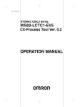
 本社
シングルポイントロードセル
SINGLE POINT BEAM LOAD CELL
L C B 0 3 シリーズ
LCB03 Series
〒 1 7 0 - 0 0 1 3 東京都豊島区東池袋 3 - 2 3 - 1 4 (ダイハツ・
ニッセイ池袋ビル 5 F )
T E L 0 3 - 5 3 9 1 - 6 1 2 6(直) F A X 0 3 - 5 3 9 1 - 6 12 9
1 . 概要
● LCB03 シリーズは、長さ 130mm 高さ 22mm の小型設計、ローコストタイプのロード
セルです。計量、配合、充填用の計量台に最適です。シングルポイントロードセ
ルなので計量機器をシンプルに製作することができます。
●ロードセルは精度や応答性に優れている分、設置環境や構造に配慮が必要になり
ます。 正しい設置を行うには静的な条件のみでなく、ショックや振動を含めた
ダイナミックな面の検討も必要です。高精度のパフォーマンスを得るために
本取扱説明書を熟読の上、ロードセルを正しく設置してください。
1. INTRODUCTION
The LCB03 series single point beam load cells are compact (130 mm
length, 22 mm height) and low cost, optimum as platforms for from ordinary weighing to platforms for mixing and filling. Being of a single point
design allows for simplified weighing system construction.
To install the load cell properly, the static conditions, as well as dynamic
factors (i.e., shock and vibration) must be considered.
To obtain the best performance from the load cell, read this instruction
manual before installation.
2. SPECIFICATIONS
2.仕様
定格出力 ............... 2mV/V±10%
最大許容過負荷 ........ 150% OF R.C.
総合誤差 ............. 0.02% OF R.O.
ゼロバランス .......... ±5% OF R.O.
温度補償範囲 ......... −10℃∼40℃
最大印加電圧 ................... 15V
最大積載面 ............. 300×300mm
許容モーメント .. (定格容量)× 7.5 N・cm
入力端子間抵抗 .................. 420 Ω± 30 Ω
出力端子間抵抗 ................... 350 Ω± 5 Ω
絶縁抵抗 .................. 2000MΩ以上/DC50V
ゼロ点の温度影響 .......... 0.023% OF R.O./10℃
出力の温度影響 ............ 0.014% OF LOAD/10℃
ケーブル太さ・長さ .............. φ 3.5 × 0.4m
3.設置にあたっての注意点
注意
本体の樹脂コーティング部を傷つけないよう取扱ってください。また設置時
にロードセルに過負荷がかからないようご注意ください。
3− 1 ベースへの設置
(1) ベースには剛性の有るものを使用してください。 ベースが簡単に傾いたり、
曲がったりすると精度に悪影響を及ぼします。
(2) ベースとロードセルの間に、厚さ 2 m m 以上のスペーサを入れてください。
(3) ロードセル取付面、及びスペーサは表面粗さ 25 μ mRa 以下に仕上げてくださ
い。
(4) ベースへの取付けには、強度区分 10.9 相当以上の六角穴付ボルトまたは、
ハイテンション六角ボルトを使用してください。 一般的な市販ボルト
(低引張強度)は強度が不足しますので、使用しないでください。 ボルト
の推奨締め付けトルクは表−1の通りです。
表−1
(5)ロードセルを取付ける前に、取付面に付着しているゴミ等を必ず取り除いて
ください。ボルトを締め付ける時は、ロードセルの固定側を押さえながら
行ってください。(図−1参照)
3−2プラットホームの取付け
(1) ロードセルの性能を長期間維持するために、プラットホームや風袋等による
負荷は出来る限り小さくしてください。
(2) プラットホームとロードセルの間に、厚さ 2mm 以上のスペーサを入れてくだ
さい。
(3) ロードセル取付面、及びスペーサは表面粗さ 25 μ mRa 以下に仕上げてくださ
い。
(4) プラットホームの取付けには、強度区分 1 0 . 9 相当以上の六角穴付ボルト
または、ハイテンション六角ボルトを使用してください。一般的な市販ボルト
(低引張強度)は強度が不足しますので、使用しないでください。 ボルト
の推奨締め付けトルクは表−1の通りです。
(5) ロードセルを取付ける前に、取付面に付着しているゴミ等を必ず取り除いて
ください。ボルトを締め付ける時はロードセルに不用な負荷(ねじりや、
横荷重等)を加えないように注意してください。
(6) プラットホームの許容寸法は図−1を参照してください。また、プラット
ホームの設計には過負荷に関する注意事項を参照してください。
WM:PD4000328
Rated output ............................................................................... 2mV/V 10%
Maximum safe overload ............................................ 150% of rated capacity
Combined error ........................................................... 0.02% of rated output
Zero balance ................................................................... 5% of rated output
Compensated temperature range ............................................ -10 to 40
Maximum excitation voltage ...................................................................... 15V
Input terminal resistance .............................................................. 420
30
Output terminal resistance ............................................................. 350 5
Insulation resistance ........................................... 2000M or over at 50VDC
Temperature effect on zero .............................. 0.023% of rated output/ 10
Temperature effect on span ...................................... 0.014% of LOAD/ 10
Cable thickness/length ................................................................ 3.5 0.4m
Maximum loading area ................................................... 300 mm 300 mm
Maximum moment ......................................... (Rated capacities) X 75 N cm
3. NOTES ON INSTALLATION
NOTE
Use care not to damage the resin coating of the load cell. When
installing, do not apply excessive load to the load cell.
3-1 INSTALLING ON A BASE
(1) The base should be rigid to prevent it from slanting or curving under
normal operating conditions.
If the base yields, the platform will bend and adversely affect the load
cell.
(2) Insert a spacer of 2 mm or greater between the load cell and the base.
(3) Use a highly rigid base. The mounting surface for the load cell and the
spacer requires a surface finish of at least 25 mRa (JIS*).
*JIS=Japan Industrial Standard
(4) Use hexagon socket head bolts (tensile strength Class 10.9-JIS or over)
or high-tension hexagon head bolts (tensile strength Class 10.9-JIS or
over) to attach the load cell on the base. Table 1 shows the applicable
clamping torque. Be sure to avoid using ordinary bolts (of a lower tensile
strength) available on the market.
Table 1
(5) Make sure that the attaching surface is clean and free from foreign matter.
Tighten the bolts while holding the securing end of the load cell.
3-2 ATTACHING THE PLATFORM
(1) The tare and the platform should be as light as possible to prolong the
service life and excellent performance of the load cell.
(2) Insert a spacer with 2 mm or greater between the load cell and the
platform.
(3) Use a platform fixture with high rigidity. The mounting surface for the
load cell and the spacer requires a surface finish of 25 mRa (JIS*) or
less.
(4) Use hexagon socket head bolts (tensile strength Class 10.9-JIS or over)
or high-tension hexagon head bolts (tensile strength Class 10.9-JIS or
over) to attach the platform fixture to the load cell. Table 1 shows the
applicable clamping torque. Avoid using ordinary bolts (of low tensile
strength) available on the market.
(5) Make sure that the attaching surface is clean and free from foreign matter.
Tighten the bolts while using much care not to apply unnecessary force
(torsion or lateral load) to the load cell.
(6)For the allowable dimensions of the platform, see Figure 1. Also, when
designing a platform, see the "3-3 OVERLOAD PRECAUTIONS" .
3-3 OVERLOAD PRECAUTIONS
(1) Mechanical strength of the load cell
When a load is applied to the center of the load cell, a load of less than
150% of the rated capacity will not cause any trouble.
However, the allowance range of the overload is reduced as the loading
point shifts from the center of the load cell. Therefore, the allowable limit at
the corner load points of the platform should be 100% of the rated capacity.
Repeated overloading, exceeding the allowable limit, may shorten the service
life of the load cell, and may even destroy it in extreme cases.
Where there is a possibility that a load may exceed the allowable limit,
attach an overload stopper to protect the load cell as described below.
(2) Overload stopper
If excessive shock is applied when positioning an object on the platform, the load may
exceed the allowable limit. Therefore, be sure
to attach an overload stopper just below the
load end of the load cell.
[Recommended installation]
Attach the overload stopper so that the
stopper comes into contact with the load cell
with as wide an area as possible when 150%
of measurement load plus the platform weight
(Here after referred to as F.S. ).
(See Figure 2.)
(3) Corner stopper
Although the overload stopper is properly adjusted, if an overload is applied to the corners of
the platform, it may exceed the allowable limit
due to the flexibility of the base. Therefore, be
sure to attach corner stoppers.
[Recommended installation]
Attach the corner stoppers so that the stoppers
come into contact with the bottom of the
weighing platform with as wide an area as
possible when 100% of F.S. is applied to each
the four corners of the platform.
(See Figure 3.)
(4) If an overload or excessive shock force is likely to occur, overlay the platform
with a shock absorbing pad or select a load cell with a rated capacity that
is double or triple the F.S. value.
(5) If a moment greater than the specified maximum value is applied to the
center of the load cell, the load cell may not function properly. Especially
when the load is over one-half of the rated capacity, it may cause the
moment to exceed the specified maximum value, even within the maximum
loading area. Under such a condition, place the center of the load on the
platform directly above the center of the loading area so that the maximum
moment will not be exceeded.
The moment applied to the load cell can be obtained as follows:
(Moment[N cm])=(Distance from the center of gravity of the object to the
load cell center[cm])x(mass of the object[kg])x10
3-4 CABLE COLOR CODE / TREMINAL TYPE
RED ............. EXC +
WHITE ................ EXC GREEN ........ SIG +
BLUE .................. SIG YELLOW ..... SHIELD
4. MAINTENANCE
(1) Remove all dirt and dust from the load cell, and always use it in a clean
environment.
(2) Use a blower to clean the load cell. Do not wash using water.
(3) Periodically inspect the overload stopper and corner stoppers.
5. DIMENSION
3−3過負荷に関する注意事項
(1)許容過負荷について
負荷の位置がロードセルの中心であれば、許 容 さ れ る 負 荷 は 定 格 容 量
の 150%ですが、負荷の位置がロードセルの中心から離れると、それに従っ
て許容される負荷は減少します。最大積載面の四隅の位置に負荷する場
合、許容される負荷は 100%となります。
ロードセルに加わる負荷が許容限度以下であれば何ら問題となることは
ありませんが、許容限度を超える負荷が加わりますと、ロードセルの性能、
機能が維持できなくなり、寿命を短くすることにもなります。
許容限度を超える負荷が加わる可能性のある場合は、以下に述べるような
ロードセルを保護するストッパを必ず設置してください。
(2)過負荷ストッパ
プラットホームに負荷を加える場合、わ
ずかでも衝撃力が伴うと容易に許容限度
以上の負荷が加わります。従って、ロー
ドセル負荷側の直下には必ず過負荷ス
トッパを設けてください。
[ 推奨設置方法]
過負荷ストッパはロードセルの中心に
測定負荷とプラットフォームや風袋を
加えた負荷(以下 F.S.)の 150% を加えた
時に、ロードセルと接触するように設置
してください。 この時出来るだけ大きな
面積でロードセルと接するようにしてく
ださい。(図−2参照)
(3)四隅ストッパ
過負荷ストッパが正しく調整されていて
も、プラットホームの四隅に許容限度を
超える負荷が加えられると、ベースの
たわみ等により過負荷ストッパは正しく
機能しません。従って、プラットホーム
の四隅には必ず四隅ストッパを設けてく
ださい。
[ 推奨設置方法]
四隅ストッパはプラットホームの四隅に約 100%F.S. の負荷を加えた時に、
プラットホームと接触するように設置してください。この時出来るだけ大き
な面積でプラットホームと接するようにしてください。(図−3参照)
(4)その他の保護策
衝撃力が加わりやすい場合は、プラットホーム上に衝撃を吸収する緩衝材
を敷くと良い結果が得られることもあります。また、過負荷が頻繁に加わる
場合は、定格容量が F.S. の2∼3倍程度のロードセルを使用するようご検
討願います。
(5)許容モーメントについて
本ロードセルは、ロ ー ド セ ル の 中 心 に 対 し て 許 容 モ ー メ ン ト を 超 え る
モーメントが加わると、正しく測定できない場合があります。特に負荷の大
きさが定格容量の 1/2 を超えると最大積載面の範囲内でも許容モーメントを
超えることがあります。
負荷の大きさが定格容量の 1/2 を越える場合は、負荷位置を積載面の中央寄
りの位置( 許容モーメントを超えない範囲) にしてから測定を開始してくだ
さい。なお、ロードセルに加わるモーメントは次の式により簡易的に求める
ことが出来ます。
(モーメント[N・cm])=(被計量物の重心からロードセル中心までの距離[cm])×
(被計量物の質量[kg])×10
3−4ロードセルケーブルの芯線の色と接続の対応
赤 ........ 電源+
白 ......... 電源−
緑 ........ 出力+
青 ......... 出力−
黄 ........ シールド
4.日常点検
(1) ロードセルのゴミ、ホコリ、汚物等の付着を取り除いて、常にクリーンな
状態で使用してください。
(2) 清掃する時はエアー等を使用してください。水での洗い流しは避けてくだ
さい。
(3)定期的に過荷重用ストッパ及び四隅ストッパの点検を行ってください。
5.外形寸法図