1
WITH
Warning
Not following these instructions may lead to injury to users or third
parties, or damage to property.
Be sure to keep this instruction manual for reference during use.
警告
本製品は安全のための注意事項などを守らなければ、使用者もしくは第
三者への危害・財産への損害が発生する場合があります。
取扱説明書には事故を未然に防ぐための重要な注意事項及び製品の取り扱い方を
記載しています。本書をよく読み安全にご使用ください。お読みになったあとはい
つでも見られる場所に必ず保管してください。
▋
▋Contents
AXIS summary
Key features・ ・・・・・・・・・・・・・・・・・・・・・・・・・・・・・
Heading Lock with Stick Priority・・・・・・・・・・・・・・・・・・・・・・
Included items・ ・・・・・・・・・・・・・・・・・・・・・・・・・・・・
Servos・・・・・・・・・・・・・・・・・・・・・・・・・・・・・・・・・
Specifications・・・・・・・・・・・・・・・・・・・・・・・・・・・・・・
1
2
3
3
4
Installation example - small and medium size airplanes (using PWM outputs)・ ・
Installation example - small and medium size airplanes (using XBus)・ ・・・・・
Installation example - giant scale airplane (using XBus)・ ・・・・・・・・・・・
Installation example - giant scale airplane using redundant receivers (using XBus)・
5
6
7
8
Installation examples
Steps before flight・ ・・・・・・・・・・・・・・・・・・・・・・ 9
Transmitter setup
XBus Channel mapping・ ・・・・・・・・・・・・・・・・・・・・・・・・
Connecting servos to the PWM ports・ ・・・・・・・・・・・・・・・・・・
Flight mode trims・ ・・・・・・・・・・・・・・・・・・・・・・・・・・・
Channel assignment・・・・・・・・・・・・・・・・・・・・・・・・・・・
Gyro setup
Gyro setup (using the AXIS Assistant)
Channel assignment・・・・・・・・・・・・・・・・・・・・・・・・・・・
Wing type・ ・・・・・・・・・・・・・・・・・・・・・・・・・・・・・・
Tail type・ ・・・・・・・・・・・・・・・・・・・・・・・・・・・・・・・
Limit adjust・・・・・・・・・・・・・・・・・・・・・・・・・・・・・・・
Servo travel・ ・・・・・・・・・・・・・・・・・・・・・・・・・・・・・
Gyro setup (using a JR DMSS Radio)
Channel assignment・・・・・・・・・・・・・・・・・・・・・・・・・・・
Wing type・ ・・・・・・・・・・・・・・・・・・・・・・・・・・・・・・
Tail type (TAIL TYPE)・ ・・・・・・・・・・・・・・・・・・・・・・・・・・
Limit adjust (LIMIT ADJ)・ ・・・・・・・・・・・・・・・・・・・・・・・・
Servo travel (SERVO TRAVEL)・ ・・・・・・・・・・・・・・・・・・・・・・
Mounting the AXIS・ ・・・・・・・・・・・・・・・・・・・・・・・・・・
10
12
13
14
19
20
21
22
22
23
25
27
29
30
32
Confirming gyro direction・・・・・・・・・・・・・・・・・・・・ 35
Confirmation procedure・ ・・・・・・・・・・・・・・・・・・・・・・・・ 36
Gain setting・ ・・・・・・・・・・・・・・・・・・・・・・・・・ 38
AXIS summary
▋
▋AXIS
summary
Thank you for purchasing the JR AXIS. Here you will find step by
step instructions for the required setup procedures. Please read the
manual carefully to enjoy all the features of the AXIS.
▋Key
▋
features
The JR AXIS is designed to perform without sacrificing the feeling of
natural flight, while at the same time offering extreme flight stability
with gyro control. Even with aggressive flight maneuvers, you will still
have full control. It is a new generation of airplane gyro, designed
from the ground up to offer a different approach to gyro control.
Roll axis
Pitch axis
▋Simplicity
▋
With JR's intuitive method, the AXIS is
very easy to set up by any pilot.
▋Wireless
▋
setup
Wireless setup can be performed using
your JR DMSS transmitter. Alternatively,
you can use the AXIS Assistant PC
interface to setup and tune the AXIS.
Yaw axis
▋Flexible
▋
Gyro Modes
The AXIS allows the choice of two gyro modes. One is heading lock
mode, which acts to maintain the models attitude regardless of
outside influence. The other is damping mode which acts to reduce
any disturbance about the yaw, pitch, or roll axis. These two modes
are selectable for each gyro axis.
1
AXIS summary
▋Heading
▋
Lock with Stick Priority
The AXIS features enhanced stick priority control - the heading
lock gain is changed automatically with stick position. This gives
the pilot full control of the aircraft during aggressive maneuvers,
and still allows full gyro assistance when in stable flight.
※Tips!
For those pilots who do not
usually use rudder during a
turn, deactivating heading
lock on rudder will provide
a more natural feeling.
The AXIS decreases the heading lock
effect proportional to stick position for a
more natural control feel.
▋In
▋ Flight Trim
Trimming the airplane with the AXIS gyro is very simple. First take off,
and trim the model with the gyro off. Then while the plane is flying, flip
the "TRIM SET" toggle switch to automatically set the neutral positions.
There is no need to land the airplane to set the neutral position.
2
AXIS summary
▋Included
▋
items
■ AXIS main unit
LED indicator
PWM ports
XBus output
XBus / S.BUS input
Battery port
miniUSB port
■ Double sided tape [05285]
M PE FOAM
3M PE FOAM 3
M PE FOAM
3M PE FOAM 3
■ Lead harness B 100mm [04639]
■ Operation Manual (this document)
▋Servos
▋
Only digital servos (including JR NX series servos) can be used
when plugging directly into the PWM outputs or when using XBus.
However, by using XBus converters (XB-1-PC4/XB-1-PC2/XB1-CV4/
XB1-CV2) conventional analog servos can also be used.
3
AXIS summary
▋Specifications
▋
AXIS (Advanced 3 aXis Intelligence System)
Model name
Control Axis
3 axis control: Pitch (lateral), Yaw (vertical),
Roll (longitudinal)
Input Signals
JR DMSS XBus / Futaba S.BUS System
PWM output (330Hz)
・Aileron ×2
・Rudder ×1
・Elevator ×2
・Throttle ×1
The throttle channel has a 70Hz output to be
compatible with most ESC's.
XBus Output (330Hz)
・Channel 2:Right Aileron ・Channel 6:Left Aileron
・Channel 3:Right Elevator・Channel 7:Left Elevator
・Channel 4:Rudder
・Channel 1:Throttle
Output Signals Input/Output
Note: Both PWM and XBus outputs can be used
simultaneously.
e.g. Use XBus for both right and left aileron
and use a PWM output for throttle.
Input
XBus
◯
XBus
◯
XBus
S.BUS
Output
PWM
◯
PWM
◯
Gain control
150%
100%
50%
0%
-150%
-100%
-50%
0%
Damping Gain
4
50%
100%
150%
50%
100%
150%
Heading Lock Gain
Installation examples
▋
▋Installation
examples
The input to the AXIS gyro can only be a JR XBus or Futaba S.BUS
serial connection. So please be sure to use a JR DMSS XBus or
Futaba S.BUS receiver only. The output from the AXIS is available
as both XBus and conventional PWM signals.
Warning Be sure to select a BEC (or battery) with a high current rating.
Remember the AXIS will be constantly working the servos, and current
consumption will be higher than normal. Please expect at least 2-3 times
the normal power consumption from your servos.
Caution! Be sure to perform this ground check before the maiden
flight to check for unexpected voltage reduction. Quickly move the
sticks while checking the receiver voltage using your transmitter
telemetry data. Be sure the voltage stays above a safe level for
your equipment. On an electric model it is highly recommended
you unplug the throttle connector during this procedure.
▋Installation
▋
example - small and medium size airplanes
(using PWM outputs)
PWM digital servos
Aileron
Elevator
RX Battery
XBus IN
Rudder
Throttle
Aileron【L】
(2 Aileron)
JR XBus or Futaba S.BUS receiver
Elevator【L】
(2 Elevator)
When powering the system, connect the power feed directly to the
AXIS and not the receiver.
5
Installation examples
▋Installation
▋
example - small and medium size
airplanes (using XBus)
Wanring
Be sure use a suitable high current switch such as the JR E SWITCH
D (#04507) when using high performance servos. Plug both power
outputs feeds into the XB1-HB6.
JR NX Servos
XBus OUT
XBus IN
XBus
JR XBus or Futaba
S.BUS receiver
RX Battery
XBus OUT
XBus IN
XB1-HB6
E SWITCH D [04507]
E SWITCH D [04507]
RX Battery
XBus
XB1-HB6
DIGITAL or ANALOG
SERVOS (PWM)
XB1-CV4
PWM Converter
Serial Bus Communication System
XB1-CV2
PWM Converter
Serial Bus Communication System
XB1-CV1~4
PWM CONVERTER
6
Installation examples
▋Installation
▋
example - giant scale airplane (using XBus)
XBus OUT
XBus or Futaba
S.BUS Receiver
XBus IN
XBus
Lead Harness B 100 [04639]
RX Battery
RX Battery
DIGITAL or ANALOG
SERVOS (PWM)
JR NX Servos
PWM Converter
XB1-PH2 /4
XBus Cable for HD
Center Hub
XB1-CV1~4 or
XB1-PC2/4
PWM CONVERTER
PWM Converter
7
Installation examples
▋Installation
▋
example - giant scale airplane using
redundant receivers (using XBus)
※Note Futaba S.BUS cannot be used for this installation.
CAUTION! When connecting the AXIS gyro, use the XBus LINK CABLE (#03695) for
input. For the output cable, use a LEAD HARNESS B (part#04639). Do not use any
other type of cables as a power failure may occur.
XBus
XBus
XBus IN
RX Battery
RX Battery
XBus OUT
Not for AXIS connection
DIGITAL or ANALOG
SERVOS (PWM)
XB1-CV1~4 or
XB1-PC2/4
PWM CONVERTER
XBus Signal Cable [03695]
JR NX Servos
XB1-PH2 /4
XBus Cable for HD
Center Hub
XBus OUT
XBus IN
PWM Converter
PC-D300 to 200 Power Cable
For AXIS connection
DIGITAL or ANALOG
SERVOS (PWM)
XB1-CV1~4 or
XB1-PC2/4
PWM CONVERTER
Lead Harness B 100 [04639]
JR NX Servos
XB1-PH2 /4
XBus Cable for HD
Center Hub
PWM Converter
8
XBus IN
Steps before flight
▋
▋Steps
before flight
※ Before switching on the gyro for the first time, please disconnect all linkages
from the servos to prevent any damage occurring prior to servo neutral and
end points being programmed.
PWM
Output signal
XBus
XBus
Channel mapping
Connecting servos to
the PWM ports
Refer page 12
Refer page 10
Transmitter setup
Refer page 13
Gyro Setup
Refer page 14
Channel assignment
Wing type
Limit adjust
Servo travel
AXIS Assistant
Refer page 18
AXIS Assistant
Refer page 20
AXIS Assistant
Refer page 21
AXIS Assistant
Refer page 22
DMSS TX
DMSS TX
DMSS TX
DMSS TX
Gyro direction
Refer page 31
Gain adjustment
Refer page 34
9
Refer page 23
Refer page 24
Refer page 29
Refer page 30
Transmitter setup
▋
▋Transmitter
setup
(For XBus only)
▋XBus
▋
Channel mapping
※If you are not intending to use the XBus output, skip this section
and proceed to page 12 "Connecting servos to the PWM ports"
※To map the IDs for JR NX servos or XBus converters such as
XB1-CV1-4, XB1-PC2-4, follow the instructions below.
※Perform the ID setup first.
▋Wing
▋
type (Normal)
Right Aileron => channel ID 2
(For multiple servos controlling the
right aileron, use Sub-ID 1 to 4)
Left Aileron => channel ID 6
Channel ID 6
(For multiple servos controlling
Channel ID 2
the left aileron, use Sub-ID 1 to 4)
※To control both right and left aileron with one single servo, be
sure to set the channel ID to 2.
※If t he a i r pla ne has convent iona l f laps, con nect t he f lap
servo directly to the channel 6 (FLAP) port on your receiver.
Alternatively, divide the XBus signal - PRIOR TO THE AXIS - using
a Y-harness (#04701) or XB1-HB6 (#03672) - to provide the flap
signal to the servo.
Note that channel ID 6 from the AXIS outputs left aileron even in
situations where you are using only one aileron servo.
To use a conventional flap servo on channel 6, it must be plugged
in prior to the AXIS as described above.
▋Wing
▋
type (Flaperon)
Right Aileron => channel ID 2
(For multiple servos controlling the
right aileron, use Sub-ID 1 to 4)
Left Aileron => channel ID 6
(For multiple servos controlling
the left aileron, use Sub-ID 1 to 4)
10
Channel ID 6
Channel ID 2
Transmitter setup
▋Wing
▋
type (Delta Wing)
Right Elevon => channel ID 2
(For multiple servos controlling
the right elevon, use Sub-ID 1 to 4)
Left Elevon => channel ID 3
(For multiple servos controlling
the left elevon, use Sub-ID 1 to 4)
▋Tail
▋
setting
▋Tail
▋
type (Normal)
Right Elevator => channel ID 3
(For multiple servos controlling the
right elevator, use Sub-ID 1 to 4)
Left Elevator => channel ID 7
(For multiple servos controlling the
left elevator, use Sub-ID 1 to 4)
Channel ID 3
Channel ID 2
Channel ID 4
Channel ID 3
Channel ID 7
※To control both right and left elevator with one single servo, be
sure to set the channel ID to 3.
Rudder => channel ID 4
(For multiple servos controlling the rudder, use Sub-ID 1 to 4)
▋Tail
▋
type (V-Tail)
Right Tail => channel ID 3
(For multiple servos controlling
the right tail, use Sub-ID 1 to 4)
Left Tail => channel ID 4
(For multiple servos controlling
the left tail, use Sub-ID 1 to 4)
11
Channel ID 3
Channel ID 4
Transmitter setup
▋Connecting
▋
servos to the PWM ports
( ※ Not necessary when using XBus system)
Please note that the PWM ports have a 330Hz output frequency, so
please ensure you only connect digital servos compatible with this
frequency to these ports.
Please follow the instructions on page 5 "Installation example
- small and medium size airplanes (using PWM outputs)" when
connecting the servos to the unit.
Wing type (Normal)
Right Aileron => Connect to the Aile 1 port
Left Aileron => Connect to the Aile 2 port
※Note: To control both right and left aileron with one single servo,
connect the servo to the Aile 1 port.
※If t he a i r pla ne has convent iona l f laps, con nect t he f lap
servo directly to the channel 6 (FLAP) port on your receiver.
Alternatively, divide the XBus signal - PRIOR TO THE AXIS - using
a Y-harness (#04701) or XB1-HB6 (#03672) - to provide the flap
signal to the servo.
Note that channel ID 6 from the AXIS outputs left aileron even in
situations where you are using only one aileron servo.
To use a conventional flap servo on channel 6, it must be plugged
in prior to the AXIS as described above.
Wing Type (Flaperon)
Right Aileron => Connect to the Aile 1 port
Left Aileron => Connect to the Aile 2 port
Wing Type (DELTA)
Right Elevon => Connect to the Aile 1 port
Left Elevon => Connect to the Elev 1 port
Tail type (Normal)
Right Elevator => Connect to the Elev 1 port
Left Elevator => Connect to the Elev 2 port
12
Transmitter setup
※Note: To control both right and left elevator with one single
servo, connect the servo to the Elev 1 port.
Rudder => Connect to the Rudd port
Tail type (V-Tail)
Right Tail => Connect to the Elev 1 port
Left Tail => Connect to the Rudd port
▋Flight
▋
mode trims
The AXIS must know where the stick center position is, and this
must remain consistent over all flight modes. Be sure to set the trim
system in your transmitter so trim positions are all the same over
all flight modes. In JR transmitters, set the trim system to "COM"
(common) as shown below.
※If using a transmitter other than JR, please refer to the instruction
manual provided by the manufacturer (XG14 shown below).
Confirm the value has been set to “COM”.
13
Transmitter setup
▋Channel
▋
assignment
The following channels are the essential channels to operate the
AXIS gyro.
If using a transmitter other than JR, please refer to the instruction
manual provided by the manufacturer.
Gyro gain channel
Each control’s default gain channel is rudder: channel 5, aileron:
channel 7, & elevator: channel 8.
Trim set channel
This is the channel which will activate memory of the trim values for
trim set (ie neutral position). It is set to channel 9 as default.
The trim set is activated when the trim channel switch is flipped (from
0% to +100%) at least twice within two seconds.
Flap channel
For airplanes equipped with flaperons, it is essential to assign a flap
channel. It is channel 6 as default.
(XG14 shown below)
▋PREPARATION
▋
Select the "DEVICE SEL" from
the system menu.
On the first page, select the
sw itch which w ill perfor m
flight mode switching.
On the second page, change
channel 5 "GEAR SW" to be
"GYRO".
14
Transmitter setup
Set channels 7 and 8 to be "GYRO" as well.
If you do not have enough channels, it is
possible to alter the gains for two or three
axis simultaneously using one channel.
This will be set later.
Default gain channels: Rudder: channel 5, Aileron: channel 7, &
Elevator: channel 8
ssignable gain channels: channel 5 - 12
A
▋Assignment
▋
of the Gain channel (XG14 shown below)
Setup the Gyro Gain (sensitivity) on each flight mode when using a
JR DMSS transmitter.
Select "GYRO SENS"
Select "GYRO SENS" from FUNCTION LIST.
Setup gain control on each flight mode
"D" stands for Damping mode, "H" stands
for Heading Lock mode. We can set different
gains for each of the three flight modes.
Note: Using custom flight modes it is possible to setup further flight
modes, each with different gain values. The availability of custom
flight modes depends on your transmitter. For example, the XG8
allows 5 flight modes, the XG11 6 flight modes, etc.
Please ensure one flight mode (flight mode 0 below) has gains set
to '0' for all three axes. This will ensure the gyros are all turned off
in one flight mode.
15
Transmitter setup
▋Setup
▋
gyro gain changing switch
Select the switch you would like
to use for changing gyro gain. By
selecting "AUTO", the Flight Mode
sw itch w ill be assigned to a lso
control the gyro gain.
It is also possible to have a "DELAY"
during gain switching.
▋TRIM
▋
SET Channel
It is essential to reset the trim center
position for the AXIS gyro if trim
adjustments are necessary during flight. A dedicated channel is best
used to reset the trim positions during flight. Trim positions are also
memorized each time the unit is powered on. If you are unable to dedicate
a specific channel to trim set, it is possible to trim the model, land, and
cycle the system power to memorize the current trim positions.
How to memorize the trim adjustment during the flight
1) Program one flight mode with the gyros turned off ("0" gain
value). Fly the model and adjust the transmitter trim.
2)Flip the trim set switch at least twice within 2 seconds. The gyro
now memorizes this trim position.
When this step is performed, the AXIS LED will flash green three
times.
Default trim set channel :channel 9
Assignable trim set channels :channel 5 - 12
Note it is very important not to use the aileron, elevator or
rudder sticks while flipping the trim set switch!
▋FLAP
▋
Channel
Assign the flap channel here, for Flaperons.
Default flap channel: channel 6
Assignable flap channels: channel 5 - 12
16
Gyro setup
▋
▋Gyro
setup
This section explains the essential parameters including channel
assignment, wing type, limit adjust and servo travel.
There are two ways of setting up the AXIS. Either using a
Windows PC, or using a JR DMSS transmitter.
When using a Window PC, please download and install the AXIS
Assistant software. The latest version is available from the JR
download page:
http://jrpropo.co.jp/english/dl/
For more information on using the AXIS Assistant, please
proceed to page 18 "Gyro setup (using the AXIS Assistant)".
Setting up the AXIS using a JR DMSS transmitter.
Please proceed to page 23 "Gyro setup (using a JR DMSS
Radio)".
※Please note you may need to have the latest firmware on your
radio. Please check the JR download page for the latest version:
http://jrpropo.co.jp/english/dl/
17
Gyro setup
▋Gyro
▋
setup (using the AXIS Assistant)
▋About
▋
the AXIS Assistant
Select the corresponding
serial system of XBus or
S.BUS here.
The AXIS Assistant is a dedicated setup interface for Windows.
By connecting the AXIS and your PC using a standard mini USB
cable, you will be able to carry out all the required setup.
▋Startup
▋
guide
①Connect your receiver to the AXIS (first follow your transmitter
manual to bind the transmitter to the receiver). Connect all
servos to the AXIS. Finally connect the battery to the AXIS and
confirm servo movement.
②Connect the AXIS to the PC using a mini USB cable.
③Launch the AXIS Assistant software.
The indicator on the left upper corner will change from red to
green when the connection has been completed. This shows the
AXIS is ready for setup.
18
Gyro setup
▋Channel
▋
assignment
▋Control
▋
Channels
Channels one to four are assigned to
Throttle, Aileron, Elevator and Rudder.
Move the sticks and confirm the sliders
in the software move correctly.
▋Flap
▋
Channel (Flap)
Please select the channel used in your transmitter
to control the f laperon function. Disable this
function if the flap is not being used by selecting
"X" for the channel designation.
▋Gyro
▋
Function Channels
Here you indicate t he channels
previously selected in your transmitter
t o c o n t r o l g y r o g a i n ( p a g e 15
"Assignment of the Gain channel").
Select t he channel numbers you
assigned for each axis.
Note you can use one channel to control
the gains on all three axes.
Trim Set
Select here the channel chosen in your transmitter
to control the trim set function. The trim set
function can be disabled by selecting "X" for the
channel designation. Only do this if you have determined it not
necessary to have trim adjustment during flight.
Check the TRIM SET function by flipping the switch you have
assigned twice within 2 seconds. When the trim is set, the LED on
the AXIS will flash green three times.
19
Gyro setup
▋Wing
▋
type
※Note: The transmitter "SYSTEM LIST" wing type must always be
set to "NORMAL", regardless of configuration on the model.
The actual model Wing Type should then be set using AXIS
Assistant shown below.
First, select the required wing type "NORMAL/FLAPERON/DELTA".
▋Under
▋
(NORMAL) Wing setting
Reverse setting
This function reverses the servo
operating direction for the LEFT &
RIGHT Aileron.
Up/down Trim
To adjust the trim center, both right
and left aileron move in the same
direction to obtain a precise center.
Aileron Trim
The aileron trim is adjusted through the aileron trim (and sub
trim) on the transmitter.
▋Under
▋
(FLAPERON) Wing setting
Reverse setting
If flap activation causes an aileron
type response, or aileron activation
causes a flap type movement, this
function allows correction of movement direction.
Aileron Trim / Flap Trim
Aileron Trim and Flap Trim are adjusted by the corresponding
trims on the transmitter.
▋Under
▋
(DELTA) Wing setting
Reverse setting
If elevator stick movement results in
an aileron type response, or if aileron
stick movement results in an elevator
type response, this function is used to ensure the movement
directions are correct.
20
Gyro setup
Aileron Trim/ Elevator Trim
Aileron trim and elevator trim are adjusted by the corresponding
trims on the transmitter.
▋Tail
▋
type
※Note: The transmitter "SYSTEM LIST" tail type must always be
set to "NORMAL", regardless of configuration on the model.
The actual model Tail Type should then be set using AXIS
Assistant shown below.
First, select the required tail type "NORMAL / V-Tail".
▋Under
▋
(NORMAL) Tail setting
Reverse setting
If you are using one or two elevator
servos and they move incorrectly, use
this function to reverse the servos so
both elevator halves move the same way.
Sync Trim
This function is used to equalize the
horizontal angle of both right and left
elevator.
Elevator Trim
The elevator trim is adjusted using the elevator trim (and sub
trim) on the transmitter.
▋Under
▋
(V-TAIL) Tail setting
Reverse setting
If moving the elevator stick on the
transmitter causes a rudder type
movement on the plane, or if rudder
stick movement on the transmitter
causes a elevator type response on
the plane, this function is used to
get the correct response.
Elevator Trim/Rudder Tim
The elevator and rudder trims (and sub trims) are adjusted from
the transmitter in the normal way.
21
Gyro setup
▋Limit
▋
adjust
This function memorizes the maximum
travel for each control surface.
①Click on the Start button (a "Complete"
button will be displayed)
②Move the right and left sticks on
the transmitter through their full
range of movement. Be sure to move
through the maximum travel otherwise the AXIS gyro will not
be able to use the full control amount possible.
Note: Any dual rate settings can be added later in the transmitter
as required.
③After moving the sticks through their maximum travel, click on
the "Complete"button to exit calibration.
④Be sure to check the actual movement of the servos and/or
control surfaces for required travel.
Note: This setting can be redone at anytime by clicking on the start
button.
▋Servo
▋
travel
After performing limit
adjustment, it is possible
to fine tune the required
servo movement with
dual aileron and elevator
servos using the AXIS
Assistant software.
①If the right and left ailerons move different amounts, use the
sliders to equalize control surface movement.
②For dual elevators, follow the same method to adjust servo
travels.
After completion of the these settings, be sure to check the actual
aileron and elevator movements are as expected.
22
Gyro setup
▋Gyro
▋
setup (using a JR DMSS Radio)
Select the "GYRO <ACRO>" from the XBus MENU as shown below.
(XG14 shown as an example)
Note: If you have previously used the AXIS assistant software to
set the input type to S.BUS, it is necessary to again use the AXIS
assistant software to change the input type to XBus before being
able to proceed with setup using your JR DMSS radio.
▋Channel
▋
assignment
▋Assignment
▋
of Gain Channel (GAIN CHANNEL)
Here we designate the channel(s) which were assigned to gyro gain
on page 14 "Channel assignment".
As earlier described, gains on each of the three axes can be
controlled together or independently. Select one of the axis (RUDD/
AILE/ELEV) and assign the Gain channel as required.
Select the axis…
Then designate the channel
23
Gyro setup
Follow the same procedure for other axes.
▋Assignment
▋
of the FLAP channel (FLAP CH)
If you have assigned a f laperon f lap channel on page 16, it is
essential to assign the channel here.
▋Assignment
▋
of the Trim Set Channel (TRIM SET CH)
If you have assigned a trim set channel on page 16, it is essential
to assign the channel here.
If not using this function, select "INH".
Check the "TRIM SET" function by flipping the switch you have
assigned twice within 2 seconds. When the trim is set, the LED on
the AXIS will flash green three times.
24
Gyro setup
▋Wing
▋
type
※Note: T he transmitter "SYSTEM LIST" wing type must always be
set to "NORMAL", regardless of configuration on the model. All
mixing is performed in the AXIS
The actual model Wing Type should then be set using XBus
setup screen shown below.
First, select the required wing type on the wing list "NORMAL/
FLAPERON/DELTA".
▋Under
▋
(NORMAL) Wing setting
Reverse Setting
Set the reverse for the right aileron (AILE1) and left aileron
(AILE2).
UP/DN - TRIM
This is to make a precise adjustment on both right & left
ailerons, moving them up or down simultaneously.
The number show between "+ / –" are the trim steps. After
setting the numerical value, set the cursor on either "+" or
"–" press the dial to make trim adjustments.
To RESET the trim value, select "RES" and press the "+ / –" icons.
Move the cursor to the value in the
center of the icons. Then press the
dial to select the value.
25
Gyro setup
Select the step amount here
to determine the amount of
movement of +/- icons.
Select “RES” and press the
+/- icons to reset the setting.
▋Under
▋
(FLAPERON) Wing setting
Reverse Setting
If flap activation causes an aileron type response, or aileron
activation causes a flap type movement, this function allows
correction of movement direction.
Aileron Trim / Flap Trim
Aileron Trim and Flap Trim are adjusted by the corresponding
trims on the transmitter.
▋Under
▋
(DELTA) Wing setting
Reverse Setting
If elevator stick movement results in an aileron type response,
or if aileron stick movement results in an elevator type response,
this function is used to ensure the movement directions are
correct.
Aileron Trim / Elevator Trim
Aileron trim and elevator trim are adjusted by the corresponding
trims on the transmitter.
26
Gyro setup
▋Tail
▋
type (TAIL TYPE)
※Note: The transmitter "SYSTEM LIST" tail type must always be set
to "NORMAL", regardless of configuration on the model.
The actual model Tail Type should then be set using XBus setup
screen shown below.
First, select the required tail type on the list "NORMAL / V-Tail”.
▋Under
▋
(NORMAL) Tail setting
Reverse Setting
If you are using one or two elevator servos and they move
incorrectly, use this function to reverse the servos so both
elevator halves move the same way. Right elevator (ELEV1) and
left elevator (ELEV2) are set independently.
Sync Trim
This function is used to equalize the horizontal angle of both
right and left elevator.
Elevator Trim
The elevator trim is adjusted using the elevator trim (and sub
trim) on the transmitter.
27
Gyro setup
Move the cursor to the value in the
center of the icons. Then press the
dial to select the value.
Select the step amount here
to determine the amount of
movement of +/- icons.
Select “RES” and press the
+/- icons to reset the setting.
▋Under
▋
(V-TAIL) Tail setting
Reverse Setting
If moving the elevator stick on the transmitter causes a rudder
type movement on the plane, or if rudder stick movement on the
transmitter causes a elevator type response on the plane, this
function is used to get the correct response.
Elevator Trim / Rudder Trim
The elevator and rudder trims (and sub trims) are adjusted from
the transmitter in the normal way.
28
Gyro setup
▋Limit
▋
adjust (LIMIT ADJ)
This function memorizes the maximum travel for each control surface.
①Set the cursor on "START" and press the dial (a "Complete"
button will be displayed)
②Move the right and left sticks on the transmitter through their
full range of movement. Be sure to move through the maximum
travel otherwise the AXIS gyro will not be able to use the full
control amount possible.
Note: Any dual rate settings can be added later in the transmitter
as required.
③Upon completion of giving the full travel on gimbals, Move the
cursor to the "Complete" and press the dial. (Complete will
change to "Start" )This setting can be repeated again until obtain
the correct setting.
④Upon complet ion of t he sett ing, check again to see each
control(servo) is moving in full stroke, by giving the full travel
on the Transmitter’s sticks.
Move the right and left sticks
through the maximum travel.
After depressing the dial at
“COMPLETE”, the display
will change to “START”.
29
Gyro setup
▋Servo
▋
travel (SERVO TRAVEL)
After performing limit adjustment, it is possible to fine tune the
required servo movement with dual aileron and elevator servos.
※This is not necessary with single aileron or single elevator servos.
※The purpose of this function function is to finetune the maximum
travel angle of axis.
Please make sure to move the stick through its full travel to
carry out the adjustment. The servo will not be moved when the
stick is at the neutral position.
For Aileron
If the right and left ailerons move different amounts, follow this
procedure below to to equalise control surface movement.
The number show between "+ / –" are the trim steps. After
setting the numerical value, set the cursor on either "+" or
"–" press the dial to make trim adjustments.
To RESET the trim value, select "RES" and press the "+ / –" icons.
Move the cursor to the value in the
center of the icons. Then press the
dial to select the value.
Select the step amount here
to determine the amount of
movement of +/- icons.
Select “RES” and press the
+/- icons to reset the setting.
30
Gyro setup
For the dual elevators, follow the same method to adjust servo travels.
After completion of the these settings, be sure to check the
actual aileron and elevator movements are as expected.
31
Mounting the AXIS
▋Mounting
▋
the AXIS
It is critical the mounting orientation of the AXIS gyro sensor is
correctly identified. Orientation is based on the direction of the servo
connection slot. This determines if the gyro is said to be mounted
forward or backward, left or right, vertically up or down. It may also
be mounted horizontally or vertically based on the name label.
▋Setting
▋
procedure (AXIS Assistant)
When using the AXIS Assistant software, select the picture which
corresponds to your mounting orientation.
▋Setting
▋
procedure (JR DMSS Radio)
Select the mounting orientation from the list.
32
Mounting the AXIS
▋Direction
▋
of AXIS mounting
①If the servo connector slots are facing towards the nose or tail,
and the name label facing up.
・Select this picture in the AXIS Assistant
software.
・Or select [NOR] when using a DMSS
transmitter to program the AXIS.
②If the servo connector slots are facing toward the nose or tail,
and the name label is facing a wing.
・Select this picture in the AXIS Assistant
software.
・Or select [NOR-S] when using a DMSS
transmitter to program the AXIS.
③If the servo connector slots are facing toward the Wing, and the
name label is facing up.
・Select this picture in the AXIS Assistant
software.
・Or select [HOR] when using a DMSS
transmitter to program the AXIS.
33
Mounting the AXIS
④If the servo connector slots are facing toward the wing, and the
name label is facing forward or backward.
・Select this picture in the AXIS Assistant
software.
・Or select [HOR-S] when using a DMSS
transmitter to program the AXIS.
⑤If the servo connector slots are facing toward up or down, and
the name label is facing toward the wing.
・Select this picture in the AXIS Assistant
software.
・Or select [VER-S] when using a DMSS
transmitter to program the AXIS.
⑥If the servo connector slots are facing toward up or down, and
the name label is facing toward the nose or tail.
・Select this picture in the AXIS Assistant
software.
・Or select [VER] when using a DMSS
transmitter to program the AXIS.
34
Confirming gyro direction
▋
▋Confirming
gyro direction
Tilt the airplane, and check the direction of gyro effect.
The cont rol surface movement should act to oppose a ny
movement of the aircraft. For example, if you tilt the airplane
nose down, the elevator should move up.
If the direction is incorrect, simply reverse the setting for that
axis using either the AXIS Assistant, or the corresponding menu
in your DMSS transmitter.
▋Setting
▋
procedure (AXIS Assistant)
CAUTION! When switching on power to the AXIS, do not move
the aircraft, as the AXIS first carries out a gyro calibration
process. The AXIS will fail calibration if it is moved during this
time. Also be sure not to touch the transmitter sticks during this
time. The completion of calibration will be easily recognized
when the servos stop after a reciprocating motion.
Select "Normal/Reverse" to correct the sensor direction as required
for each axis.
35
Confirming gyro direction
▋Setting
▋
procedure (JR DMSS Radio)
Select AILE/RUDD/ELEV and choose "Normal/ Reverse" to correct
the sensor direction as required for each axis.
▋Confirmation
▋
procedure
Be sure to select the heading lock mode for all three axis (aileron,
elevator and rudder) to confirm the gyro effect direction.
Gyro direction for elevator
Hold the airplane and tilt it in the pitch axis. Confirm that when
the nose is tilted DOWN, the elevator moves UP.
Nose goes UP.
Nose goes DOWN.
Elevator goes DOWN.
Elevator goes UP.
If the elevator moves in the wrong direction, reverse the sensor
direction
for the
Left wing
goesELEV
UP. Gyro.
Right wing goes UP.
For the Aileron and Rudder, follow the same method to confirm
the direction of gyro effect.
36
Left Aileron goes UP.
Right Aileron goes UP.
Confirming gyro direction
Elevator goes DOWN.
Elevator goes UP.
goes DOWN.
GyroElevator
direction
for Aileron
Elevator goes UP.
Left wing goes UP.
Right wing goes UP.
Left wing goes UP.
Right wing goes UP.
Left Aileron goes UP.
Right Aileron goes UP.
Left Aileron goes UP.
Right Aileron goes UP.
Nose goes right.
goes
left.
Nose
Gyro
direction
for rudder
Nose goes left.
Nose goes right.
Rudder moves right.
Rudder moves left.
Rudder moves right.
Rudder moves left.
37
Gain setting
▋
▋Gain
setting
The optimum gyro gain value will vary depending on your model
and equipment setup. Setting too high a gain on initial set up may
be very dangerous. It will cause unexpected flutter or hunting of
the servos and you may loose control of the model. Be sure to start
with a low gain and slowly increase the gain to find the optimum
value. Be sure to avoid using high values. This will work the servos
unnecessarily hard. The AXIS gyro will provide enough stability
even at low gain values. Carefully find the best value for the gyro
gains on each axis. When using a JR DMSS transmitter, you can
activate a "TRIM INPUT SWITCH" function so gain adjustment can
be easily and safely carried out in flight.
▋Setup
▋
for Trim Input Switch
When using a JR DMSS transmitter, you can assign a Trim Input
Switch to each gyro axis Rudder, Elevator and Aileron. Then each
trim input switch can be assigned to the corresponding gyro gain.
For example,
Assign TIS1 ~ TLS3 as a switch for gain
input on aileron, elevator and rudder.
After accessing the sub display, select
the aileron trim, then TIS1 is assigned
as aileron trim.
Next we want to assign the TIS1 to only
be active when the gyro is active.
In this example, select the gear switch
for changing the gyro gain. Position "0"
stands for having no gain it is "Zero".
The gyro is active in position 1 & 2,
and the Trim Input switch is also active
in these modes.
38
Gain setting
In the same manner, set the elevator and rudder trims as Trim
Input switches as well.
Assign the Trim Input Switch as Gain Input
The screen shot on the left shows
assigning the trim input switch to
change rudder gyro gain.
By a s sig n i ng t he Rudder Tr i m
as a Trim Input Switch TIS3, it is
possible to set the rudder gain
using the rudder trim.
Likewise, assign the Trim Input
Switch for aileron and elevator.
After completion of above settings, it is possible to adjust the
gyro gain in each flight mode on aileron, elevator and rudder.
After completing the above setup, it is possible to adjust the gyro
gains individually for each axis in each flight mode without landing.
39
▋
▋目次
AXIS 飛行機用ジャイロ概要
ごあいさつ・ ・・・・・・・・・・・・・・・・・・・・・・・・・ 41
特徴・・・・・・・・・・・・・・・・・・・・・・・・・・・・・ 41
セット内容・ ・・・・・・・・・・・・・・・・・・・・・・・・・ 43
推奨サーボ・・・・・・・・・・・・・・・・・・・・・・・・・・ 43
仕様・・・・・・・・・・・・・・・・・・・・・・・・・・・・・ 44
搭載 ( 接続 ) 例
中型 - 小型機 への搭載例 1 (PWM)・・・・・・・・・・・・・・・・ 45
中型 - 小型機 への搭載例 2 (XBus)・・・・・・・・・・・・・・・・ 46
大型機への搭載例 1 (XBus)・・・・・・・・・・・・・・・・・・・ 47
大型機への搭載例 2 (XBus) リダンダントレシーバー仕様・ ・・・・・ 48
飛行までの手順・・・・・・・・・・・・・・・・・・・・・ 49
プロポの設定
XBus チャンネル ID 設定・ ・・・・・・・・・・・・・・・・・・・ 50
PWM 出力ポート接続・ ・・・・・・・・・・・・・・・・・・・・ 52
トリムの値をフライトモードで共通にする・・・・・・・・・・・・・ 53
チャンネル割当 ( 送信機側 )・・・・・・・・・・・・・・・・・・・ 54
ジャイロセットアップ
ジャイロセットアップ (AXIS Assistant)
チャンネル割当・ ・・・・・・・・・・・・・・・・・・・・・・・ 59
ウィングタイプの設定 (Wing Type)・ ・・・・・・・・・・・・・・・ 60
テールタイプの設定 (Tail Type)・・・・・・・・・・・・・・・・・・ 61
リミットアジャスト (Limit Adjust)・ ・・・・・・・・・・・・・・・・ 61
サーボトラベル (Servo Travel)・ ・・・・・・・・・・・・・・・・・ 62
ジャイロセットアップ (DMSS 送信機 )
チャンネル割当・ ・・・・・・・・・・・・・・・・・・・・・・・ 63
ウィングタイプの設定・・・・・・・・・・・・・・・・・・・・・・ 65
テールタイプの設定 (TAIL TYPE)・ ・・・・・・・・・・・・・・・・ 67
リミットアジャスト (LIMIT ADJ)・ ・・・・・・・・・・・・・・・・・ 68
サーボトラベル (SERVO TRAVEL)・ ・・・・・・・・・・・・・・・・ 69
AXIS の搭載・ ・・・・・・・・・・・・・・・・・・・・・ 71
ジャイロ補正舵の確認・・・・・・・・・・・・・・・・・・ 74
確認方法・・・・・・・・・・・・・・・・・・・・・・・・・・・ 75
ゲイン設定・・・・・・・・・・・・・・・・・・・・・・・ 77
AXIS 飛行機用ジャイロ概要
▋
▋AXIS
飛行機用ジャイロ概要
▋ごあいさつ
▋
この度は JR の飛行機用ジャイロ AXIS をご購入頂き、誠にありがとう
ございます。
本書は AXIS の設定について順をおって説明しています。AXIS の機能
を十分にご理解いただき、その性能をご堪能ください。
▋特徴
▋
AXIS はジャイロによる飛行安定性能を極限まで高めながら、同時にナ
チュラルな操縦感を全く犠牲にする事なく、アグレッシブなマニューバの
全てをごく自然にお楽しみ頂けるように設計されており、その意味ではこ
れまでにないアプローチから生まれた新世代の飛行機専用ジャイロです。
ロール軸方向
ピッチ軸方向
ヨー軸方向
▋シンプルなセットアップ
▋
分かり易くシンプルなセットアップにより
どなたにでも簡単に設定が可能です。
▋送信機から設定可能
▋
JR 製 DMSS 送信機をご使用の方は PC
を接続しなくても送信機から無線で簡単
に設定が可能です。
▋自由度の高いゲイン設定
▋
AXIS は、ヘディングロック ( 一定の方向
を強固に維持しようとするモード ) とダンピングモード ( 揺れを抑え操
縦を容易にするモード ) の2つのモードを三軸それぞれに独立して選択
する事が出来ます。
41
AXIS 飛行機用ジャイロ概要
▋スティック優先ヘディングロック
▋
AXIS は、ヘディングロックモードのときにもスティック操作を優先します。
スティックの位置によってその効果を動的に切り替えますので自然な操
舵フィーリングが得られ、パイロットは飛行機を思いのままに操縦する
事が可能になります。
※旋回時にラダー操作をしな
い方は、ラダー方向にはヘ
ディングロックを設定しな
い事でスムーズな旋回を行
なう事が出来ます。
舵の量に応じてジャイロの効果を動
的に変更。より自然な操舵感がえら
れます。
▋インフライトトリムリセット
▋
ジャイロの使用時には、トリム合わせの手順が少し異なります。
AXIS は上空でトリム合わせを行ない、飛行しながらワンタッチで正しい
トリム位置を AXIS にセットする事が出来ます。
42
AXIS 飛行機用ジャイロ概要
▋セット内容
▋
■ AXIS 本体
LED インジケータ
サーボ接続ポート
XBus 出力ポート
XBus / S.BUS 入力ポート
バッテリー接続ポート
miniUSB 接続ポート
■ AXIS 固定用両面テープ [05285]
M PE FOAM
3M PE FOAM 3
M PE FOAM
3M PE FOAM 3
■ リードハーネス B 100mm [04639]
■ 取扱説明書 ( 本書 )
▋推奨サーボ
▋
デジタルサーボ (NX シリーズを含む )
XBus 接続でコンバータを介した場合のみアナログサーボも使用可能です。
PWM コンバータ (XB1-PC4 / XB1-PC2 / XB1-CV4 / XB1-CV2) 2014
年 8 月現在
43
AXIS 飛行機用ジャイロ概要
▋仕様
▋
型式
AXIS (Advanced 3aXis Intelligence System)
制御
3軸制御
ピッチ ( 縦 )・ヨー ( 左右 )・ロール ( 回転 )
入力
XBus (JR) / S.BUS (Futaba)
PWM 出力 (330Hz)
・エルロン ×2
・ラダー ×1
・エレベータ×2
・スロットル ×1
スロットルは一般的な ESC に対応する為、出力は
70Hz としています。
XBus 出力 (330Hz)
・チャンネル 2 :右エルロン ・チャンネル 6:左エルロン
・チャンネル 3 :右エレベータ ・チャンネル 7 :左エレベータ
・チャンネル 4 :ラダー
・チャンネル 1 :スロットル
出力
入出力
XBus 出力と PWM 出力は、同時に使用する事が出
来ます。
例 )動 翼 は XBus 出 力 を 使 用し、 スロットル は
PWM を使用するなど。
入力
XBus
◯
XBus
◯
XBus
S.BUS
出力
PWM
◯
PWM
◯
ゲインコントロールイメージ
150%
-150%
100%
50%
0%
-100%
-50%
0%
ダンピングゲイン
44
50%
100%
150%
50%
100%
150%
ヘディングロックゲイン
搭載 ( 接続 ) 例
▋
▋搭載
( 接続 ) 例
AXIS は XBus もしくは S.BUS のいずれかの入力が必要です。
XBus 出力に対応した受信機か、S.BUS 出力対応の受信機でご使用くださ
い。
出力には、PWM / XBus の両方が使用出来ます。(S.BUS 出力はあり
ません。)
AXIS の働きによって常にサーボがコントロールされますので AXIS なしの
時と比べて2〜3倍のバッテリー容量を確保するようにしてください。
※電動機で BEC 付きアンプを使用する場合は、電流許容値が十分に
確保されているかを必ず確認してください。
注意 ! 飛行前に必ず地上でスティックを素早く操作し、テレメトリで受信機
電圧の低下が起こらない事を確認してください。
スロットルが接続されていると危険ですので、スロットルチャンネル
を接続せずにテストする事をお勧めします。
▋中型
▋
- 小型機 への搭載例 1 (PWM)
PWM デジタルサーボ
エルロン
エレベータ
受信機用
バッテリー
XBus IN
ラダー
スロットル
エルロン【L】
(2 エルロン時 )
XBus、又は S.BUS 出力に対応した受信機
エレベータ【L】
(2 エレベータ時 )
※バッテリーは受信機側ではなく、必ず AXIS 本体に接続してください。
45
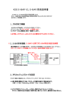
搭載 ( 接続 ) 例
▋中型
▋
- 小型機 への搭載例 2 (XBus)
注意! ハイパフォーマンスサーボを使用する場合は、電源スイッチに[電
子スイッチ D]等の高容量対応スイッチを使用し、XB1-HB6 に出力端
子を 2 本とも挿して十分な電源供給を心掛けてください。
XBus OUT
JR NX シリーズ サーボ
XBus IN
XBus
XBus、又は S.BUS 出
力に対応した受信機
受信機用
バッテリー
XBus OUT
XBus IN
XB1-HB6
E スイッチ D [04507]
E スイッチ D [04507]
受信機用
バッテリー
XBus
XB1-HB6
従来型 (PWM) サーボ
( アナログ含む )
XB1-CV4
PWM Converter
Serial Bus Communication System
XB1-CV2
PWM Converter
Serial Bus Communication System
XB1-CV1~4 等の
PWM コンバータ
46
搭載 ( 接続 ) 例
▋大型機への搭載例
▋
1 (XBus)
XBus OUT
XBus、又は S.BUS 出
力に対応した受信機
XBus IN
XBus
リードハーネス B 100 [04639]
受信機用バッテリー
受信機用バッテリー
従来型 (PWM) サーボ
( アナログ含む )
JR NX シリーズサーボ
PWM Converter
XB1-PH2・4 等の
HD センターハブ用
XBus ケーブル
XB1-CV1~4 または
XB1-PC2/4 等の
PWM コンバータ
PWM Converter
47
搭載 ( 接続 ) 例
▋大型機への搭載例
▋
2 (XBus) リダンダントレシーバー仕様
※本搭載例では S.BUS 受信機は使用できません。
注 意 ! AXIS の入力用ケーブルは、必ず、XBus リンクケーブル ( 品番
03695) を、また、出力ケーブルにはリードハーネス B( 品番 04639) を
使用してください。他のケーブルを使用すると XB1-CHB からの電源供
給がえられず電力不足になるため大変危険です。
XBus
XBus
XBus IN
受信機用
バッテリー
受信機用
バッテリー
XBus OUT.
ジャイロ不要なサーボ
従来型 (PWM) サーボ
( アナログ含む )
XB1-CV1~4 または
XB1-PC2/4 等の
PWM コンバータ
XBusリンクケーブル [03695]
JR NX シリーズ
サーボ
XB1-PH2・4 等の
HD センターハブ用
XBus ケーブル
XBus OUT
XBus IN
PWM Converter
PC-D300~1200 大電流用ケーブル
AXIS の制御が必要なサーボ
従来型 (PWM) サーボ
( アナログ含む )
XB1-CV1~4 または
XB1-PC2/4 等の
PWM コンバータ
リードハーネスB 100 [04639]
JR NX シリーズ
サーボ
XB1-PH2・4 等の
HD センターハブ用
XBus ケーブル
PWM Converter
48
XBus IN
飛行までの手順
▋
▋飛行までの手順
受信機の出力
※ジャイロ搭載後、初めて電源をいれる
際は、サーボホーンを外すなどして機
体の破損を防いでください。
PWM
XBus
XBus
チャンネル ID 設定
PWM 出力ポート接続
50 ページ参照
52 ページ参照
プロポの設定
53 ページ参照
ジャイロセットアップ
チャンネル割当
ウイングタイプ設定
リミットアジャスト
サーボトラベル
54 ページ参照
AXIS Assistant
58 ページ参照
AXIS Assistant
60 ページ参照
AXIS Assistant
61 ページ参照
AXIS Assistant
62 ページ参照
DMSS 送信機
DMSS 送信機
DMSS 送信機
DMSS 送信機
ジャイロ補正舵の確認
74 ページ参照
ゲイン設定
77 ページ参照
49
63 ページ参照
65 ページ参照
68 ページ参照
69 ページ参照
プロポの設定
▋
▋プロポの設定
▋XBus
▋
チャンネル ID 設定
(XBus 出力を使用時 )
※Xbus 出力を使用しない場 合は、52 ページの「PWM 出力ポート接
続」へ進んでください。
※この時点ではまだリンケージをせず、ID のみをセットします。
▋ウイング設定
▋
▋ウイングタイプ
▋
( ノーマル )
右エルロン → チャンネル ID 2
( 複数サーボを使用するときはサブ
ID1 〜4を使用 )
左エルロン → チャンネル ID 6
( 複数サーボを使用するときはサブ
ID1 〜4を使用 )
チャンネル ID 6
チャンネル ID 2
※左右のエルロンを1つのサーボでコントロールする機体の場合は、
チャンネル ID を2に設定してください。
※フラップ付きの機 体の場 合は、直 接 受信 機の6ch(FLAP) にフ
ラップ サ ーボ を 接 続 するか、Y- ハ ーネス (04701) もしくは XB1HB6(03672) を使用して XBus 信号を分岐して AXIS を通さずにサー
ボを接続して下さい。
※AXIS からの出力されるチャンネルや XBus 信号 ID6 は左エルロンと
して出力されますが、受信機からの出力は、フラップチャンネルとし
て機能します。
▋ウイングタイプ
▋
( フラッペロン )
右エルロン → チャンネル ID 2
( 複数サーボを使用するときはサブ
ID1 〜4を使用 )
左エルロン → チャンネル ID 6
( 複数サーボを使用するときはサブ
ID1 〜4を使用 )
50
チャンネル ID 6
チャンネル ID 2
プロポの設定
▋ウィングタイプ
▋
( デルタ )
右エレボン → チャンネル ID 2
( 複 数 サーボを使 用するときはサブ
ID1 〜4を使用 )
左エレボン → チャンネル ID 3
( 複数サーボを使用するときはサブ
ID1 〜4を使用 )
▋テール設定
▋
チャンネル ID 3
チャンネル ID 2
チャンネル ID 4
▋テールタイプ
▋
( ノーマル )
右エレベータ → チャンネル ID 3
( 複 数 サーボを使 用するときはサブ
ID1 〜4を使用 )
左エレベータ → チャンネル ID 7
( 複 数 サーボを使 用するときはサブ
ID1 〜4を使用 )
チャンネル ID 3
チャンネル ID 7
※左右のエレベータを1つのサーボでコントロールする機体の場合は、
チャンネル ID を3に設定してください。
ラダー → チャンネル ID 4
( 複数サーボを使用するときはサブ ID1 〜4を使用 )
▋テールタイプ
▋
(V- テール )
右テール → チャンネル ID 3
( 複数サーボを使用するときはサブ
ID1 〜4使用 )
左テール → チャンネル ID 4
( 複数サーボを使用するときはサブ
ID1 〜4を使用 )
51
チャンネル ID 3
チャンネル ID 4
プロポの設定
▋PWM
▋
出力ポート接続 (XBus 出力を使用する場合は不要です。)
AXIS の PWM 出力ポートを使用してサーボを接続する場合は、下記の
要領で接続してください。(45 ページの「中型 - 小型機 への搭載例 1
(PWM)」を参照ください。)
ウイングタイプ ( ノーマル )
右エルロン → AILE 1 ポートに接続
左エルロン → AILE 2 ポートに接続
※左右のエルロンを1つのサーボでコントロールする機体の場合は、
AILE 1 ポートに接続してください。
※フラップ付きの 機 体 の 場 合 は、 直 接 受 信 機 の 6ch(FLAP) にフ
ラップ サ ーボ を 接 続 するか、Y- ハ ーネス (04701) もしくは XB1HB6(03672) を使用して XBus 信号を分岐して AXIS を通さずにサー
ボを接続して下さい。
※AXIS からの出力されるチャンネルや XBus 信号 ID6 は左エルロンと
して出力されますが、受信機からの出力は、フラップチャンネルとし
て機能します。
ウィングタイプ ( フラッペロン )
右エルロン → AILE 1 ポートに接続
左エルロン → AILE 2 ポートに接続
ウィングタイプ ( デルタ )
右エレボン → AILE 1 ポートに接続
左エレボン → ELEV 1 ポートに接続
テールタイプ ( ノーマル )
右エレベータ → ELEV 1 ポートに接続
左エレベータ → ELEV 2 ポートに接続
※左右のエレベータを1つのサーボでコントロールする機体の場合は、
ELEV 1 ポートに接続してください。
ラダー → RUDD ポートに接続
テールタイプ (V- テール )
右テール → ELEV 1 ポートに接続
左テール → RUDD ポートに接続
52
プロポの設定
▋トリムの値をフライ
▋
トモードで共通にする
AXIS は飛行機がまっすぐに飛ぶ時のトリムを基準として中点をセットし
ますので、フライトモード毎にトリムが変ると思いがけない姿勢変化を
起こします。
これを防止する為に、フライトモード毎にトリムが変化しないモードに
する必要があります。
他社製送信機をご使用の場合にも同様の設定を行なってください。( 各
社マニュアルを参照ください。)
※JR 送信機の場合、特に設定を行なわなくても既定値は「トリム共通」
となっていますが、念のためプロポの設定が下記のようになっている
か確認してください。( 例:XG14)
フライトモード トリム設定を「COM」に設定
53
プロポの設定
▋チャンネル割当
▋
( 送信機側 )
DMSS 送信機で、AXIS のコントロールに必要なチャンネルを割り当てます。
AXIS のコントロールに必要なチャンネルは下記の通りです。
他社製送信機をご使用の際も同様の設定を行ってください。
( 各社マニュ
アルをご使用ください。)
ジャイロゲイン送信用チャンネル
各舵用の既定値はラダー
(5ch)
、
エルロン
(7ch)
、
エレベータ
(8ch)です。
トリムセット送信用チャンネル
飛行中にトリムの位置をジャイロにセットする指令を送信するチャンネルで
す。 既定値は(9ch)です。
トリムセット用チャンネルは、0%〜+100%で有効となります。
フラップチャンネル
フラッペロン付きの機体の場合は、ここでフラップチャンネルを指定します。
既定値は(6ch)です。
( 例:XG14)
▋準備
▋
SYSTEM LIST か ら DEVICE SEL
を選択します。
DEVICE SELECT 1 ページ目で
はフライトモードの切り替えに
使用するスイッチを選択します。
5ch をジャイロゲイン用のチャ
ンネル にする為 OUT を [ACT]
から [GYRO] に変更します。
54
プロポの設定
7ch、8ch も同様に GYRO に設定します。
空きチャンネルが十分にない場合、3軸 ( ラ
ダー、エルロン、エレベータ ) とも同じチャ
ンネルを指定する事が出来ます。2軸共通
にする場合は、2つの舵に同じチャンネルを指定する事も可能です。
既定値:ラダー 5 チャンネル、エルロン 7 チャンネル、エレベー
タ 8 チャンネル
指定範囲:5 〜 12 チャンネル
( 例:XG14)
▋ゲインチャンネルの割当
▋
▋各チャンネルにジャイロゲインを設定
▋
ラダー、エレベータ、エルロンの各チャンネルに、ジャイロゲインを設
定します。
GYRO SENS を選択
FUNCTION LIST メニューから GYRO SENS を
選択します。
フライトモード毎のゲイン設定
D はダンピングモード、H はヘディングロック
モードを表します。
フライトモードは基本 3 通りですが、カスタ
ムフライトモードを使用してさらに増やす事が
出来ます。
(フライトモードの数は送信機によっ
て異なります。)図のように1つはゲインをゼロにしてジャイロ効果の
ないモードを用意してください。
エレベータ、エルロンについても同様に設定を行ないます。
55
プロポの設定
▋切り替えスイッチの設定
▋
引き続きジャイロゲイン切換え用の
スイッチを設定します。
切換え用のスイッチはここで設定し
ます。
AUTO を選択すると、デバイスセレ
クトで指定した、フライトモードス
イッチが割り当てられます。
DELAY の項目でジャイロ感度の切
換えに遅延時間を設定可能です。
▋トリムセットチャンネル
▋
飛行中にトリム調整を行なった場合、AXIS にその位置を基準位置とし
て記憶させる必要があります。
AXIS は飛行中にトリム位置を記憶させる事が出来ます。
ここでは AXIS にトリム位置を記憶させるスイッチのチャンネルを割り当
てます。
トリムセット手順
1) ジャイロゲインが全てゼロのフライトモードで飛行させ、機体のトリ
ムを合わせます。
ジャイロが効いているとトリムのずれが分かりませんのでジャイロを
OFF( ゲインゼロ ) でトリム合わせを行なってください。
2)割り当てたスイッチチャンネルを素早く2度 ( 2秒以内 ) 動かしてくだ
さい。
トリム位置を AXIS が記憶します。 既定値:9 チャンネル
正常にトリムセットが完了すると、 指定範囲:5 〜 12 チャンネル
AXIS の LED が緑色に3度点滅します。
▋フラップチャンネル
▋
フラッペロン設定でフラップチャン
ネルをご使用になる場合は、ここで
フラップに使用するチャンネル番号
を指定します。
56
既定値:6 チャンネル
指定範囲:5 〜 12 チャンネル
ジャイロセットアップ
▋
▋ジャイロセッ
トアップ
チャンネル割当やウイングタイプ設定、リミットアジャストなどの設定を
行います。
まず送信機側の設定を行った後、AXIS の設定を行います。(「チャンネ
ル割当 ( 送信機側 )」P.54 参照 )
AXIS の設定を行うには、Windows PC または、DMSS 送信機を使用し
ます。
Windows PC を使用する場合、AXIS Assistant という専用ソフトウェ
(
アを使用します。
「ジャイロセットアップ
(AXIS Assistant)」P.58 参照 )
AXIS Assistant は、当社のホームページより最新版をダウンロードし
てご使用ください。
DMSS 送信機を使用する場合、送信機の設定画面を操作することに
よりAXIS の設定を行います。(「ジャイロセットアップ (DMSS 送信機 )」
P.63 参照 )
※送信機の基本ソフトウェア ( ファームウェア ) のバージョンによって
AXIS を設定する機能が無いことがあります。
ファームウェアは、当社のホームページから最新版をダウンロードし
てご使用ください。
当社ホームページ URL:http://www.jrpropo.com/jpn/dl/
57
ジャイロセットアップ
▋ジャイロセットアップ
▋
(AXIS Assistant)
▋AXIS
▋
Assistant について
S.BUS 入力の場 合は、
"S.BUS" を選択します。
AXIS Assistant は、AXIS を設定するための Windows 用ソフトウェア
です。
PC と AXIS を USB ケーブルで接続し、AXIS Assistant を起動すること
で、さまざまな設定を行うことができます。
▋接続方法
▋
①AXIS にバッテリーを接続します。
この時、サーボや受信機の接続は必要ありませんが、動作を確認す
るために、接続していただくことをおすすめします。
②Windows PC を起動し、USB ケーブルを使用して PC と AXIS を接
続します。
③AXIS Assistant を起動してください。
AXIS が正常に認識されると左上のインジケータが赤から緑になり、
AXIS Assistant で AXIS の設定ができるようになります。
58
ジャイロセットアップ
▋チャンネル割当
▋
▋コントロールチャンネル
▋
(Control Channels)
スロットル、エルロン、エレベータ、ラダー
の4つのコントロールチャンネルは固定値で
す。
各チャンネルに対応してスライドバーが動
きますので各チャンネルが正しく動作して
いることをご確認ください。
ウィングタイプやテールタイプ、リバース設
定等は後ほど行ないます。
▋フラップチャンネル
▋
(Flap)
フラッペロンを使用しない場合は ( × ) を選択します
▋ジャイロ機能チャンネル
▋
(Gyro function channels)
54 ペー ジ の「 チャンネ ル 割 当 ( 送 信 機
側 )」で設定したチャンネルに合わせて、3
軸 ( ラダー、エルロン、エレベータ ) の各
ゲイン送信用のチャンネルを AXIS に指定
します。
トリムセット (Trim set)
この機能を使用しない場 合は「使用しない ( × )」
を選択してください。
割り当てたスイッチチャンネルを素早く2度 ( 2秒以
内 ) 動かして、実際に割り当てたスイッチが動作することを確認してく
ださい。
59
ジャイロセットアップ
正常にトリムセットが完了すると、AXIS の LED が緑色に3度点滅し
ます。
▋ウィングタイプの設定
▋
(Wing Type)
ウィングタイプ、テールタイプ、及びリバース設定等を行ないます。
ウイングタイプの設定は、送信機ではなく AXIS( ジャイロ ) 側で行い
ますので、送信機の WING TYPE 設定 (JR の場合 SYSTEM LIST 内 ) は
NORMAL にしてください。
▋ノーマル
▋
(Normal)
リバース設定
左右それぞれのエルロンの動作方向を
逆転させたいときに使用します。
アップダウントリム
左右のエルロンを同時に上下方向に微
調整したいときに使用します。
▋フラッペロン
▋
(Flaperon)
リバース設定
フラップがエルロン動作をする、又は
エルロンがフラップ動作をしていると
きに使用します。
エルロントリム・フラップトリム
エルロントリム、フラップトリムはプロ
ポのトリムを使用して調整してください。
▋デルタ
▋
(Delta)
リバース設定
エレベータがエルロン動作をする、又
はエルロンがエレベータ動作をしてい
るときに使用します。
エルロントリム・エレベータトリム
エルロントリム、エレベータトリムはプロポのトリムを使用して調整し
てください。
60
ジャイロセットアップ
▋テールタイプの設定
▋
(Tail Type)
▋通常尾翼
▋
(Normal)
リバース設定
左右それぞれのエレベータの動作方向
を逆転させたいときに使用します。
シンクロトリム(Sync Trim)
左右のエレベータの水平角を均等にす
る際に使用します。
エレベータトリム
エレベータトリムはプロポのトリムを使
用して調整してください。
▋V
▋ テール (V-Tail)
リバース設定
エレベータがラダー動作をする、又は
ラダーがエレベータ動作をしている時
に使用します。
エレベータトリム・ラダートリム
エレベータトリム、ラダートリムはプロ
ポのトリムを使用して調整してください。
▋リミットアジャスト
▋
(Limit Adjust)
AXIS に最大舵角を記憶させます。
①Start ボタンをクリックします。( 表 示
が Complete に変ります )
②プロポのスティックを上下左右の最大
舵角まで動かします。
舵角を小さくするとジャイロの効果が
限定的になってしまいますのでここで
は動作可能な最大舵角を設定します。
※デュアルレートは別途プロポ側で設定可能です。
61
ジャイロセットアップ
③最大舵角をセットしたら Complete ボタンをクリックします。( 表示
が Start に戻ります )
本 設 定は、 何度 でも再 設 定 が可能です。 もし間 違って完了前に
Complete を押してしまってもまた、Start ボタンを押す事で再度設定
出来ます。
④設定が終わったら、もう一度プロポのスティックを上下左右の最大角ま
で動かして、きちんと各舵が最大舵角まで動く事を確認してください。
▋サーボトラベル
▋
(Servo Travel)
左 右のエルロン、エレ
ベータでサーボの最大
動作角度に違いがある
ときにその差を調整し
ます。
※エルロンがシングル
サーボの場合やエレ
ベーターがシングル
サーボの場合は、必要ありません。
①プロポのエルロンスティックを左右の最大角まで動かします。
左右どちらかのサーボを基準にして、もし舵角に違いがあれば、スラ
イダーバーで角度が均等になるよう調整します。
②エレベータについても同様の手順を行ないます。
③設定が終わったら、もう一度プロポのスティックを上下左右の最大角
まで動かして、左右のエルロン、エレベータで角度が同じである事を
確認してください。
62
ジャイロセットアップ
▋ジャイロセットアップ
▋
(DMSS 送信機 )
XBus 設定から AXIS メニューを選択します。
下図のように XBus メニューから ”GYRO<ACRO>” を選択して下さい。
※AXIS Assistant で S.BUS入力を選んでいた場合、
DMSS 送信機を使っ
てセットアップを行なう事は出来ません。再度 AXIS Assistant で入
力タイプを XBus に変更してください。
▋チャンネル割当
▋
▋ゲインチャンネルの割当
▋
(GAIN CHANNEL)
54 ページの「チャンネル割当 ( 送信機側 )」で設定したチャンネルに
合わせて3軸 ( ラダー、エルロン、エレベータ ) の各ゲイン送信用のチャ
ンネルを AXIS に指定します。
※設定を行なう軸(RUDD / AILE / ELEV)を選択し、次にそれぞれの
ゲインチャンネルを指定します。
舵を選択して・・・
チャンネルを割り当てます。
63
ジャイロセットアップ
他の舵に対しても同様に設定して下さい。
▋フラップチャンネルの割当
▋
(FLAP CH)
フラッペロン設定でフラップチャンネルをご使用になる場合は、ここで
フラップに使用するチャンネル番号を指定します。
▋トリムセットチャンネルの割当
▋
(TRIM SET CH)
この機能を使用しない場合は “INH” を選択してください。
割り当てたスイッチチャンネルを素早く2度 ( 2秒以内 ) 動かして、実際
に割り当てたスイッチが動作することを確認してください。
正常にトリムセットが完了すると AXIS の LED が緑色に3度点滅します。
※ジャイロゲインチャンネル、フラップチャンネルと同一のチャンネル番
号を選択する事はできません。
64
ジャイロセットアップ
▋ウィングタイプの設定
▋
ウィングタイプ、テールタイプ、及びリバース設定等を行ないます。
まず最初に主翼のウィングタイプを選択します。
NORMAL/FLRPERON/DELTA のいずれかを下図のリストから選択して
ください。
※[SYSTEM LIST] の [WING TYPE] はウィングタイプ、テールタイプ共に
[NORMAL] にしておいてください。
▋ノーマル
▋
(NORMAL)
リバース設定
右エルロン (AILE1)、左エルロン (AILE2) のリバース設定を行ないます。
ノーマル (NOR)/ リバース (REV) を選択してください。
アップダウン ( ↑/↓ )トリム
左右のエルロンを同時に上下方向に微調整したい時に使用します。
+ − の間にある数字はトリムステップ数です。
この値を決めた後、+ / − にカーソルを合わせてダイアルを押し
てトリム合わせを行ないます。
トリムステップで ”RES” を選択して + / − を押す事でトリムの
値をリセットする事が出来ます。
中央の数字にカーソルを合わせ
てダイヤルを押し、数値を変更し
て下さい。
65
ジャイロセットアップ
ここで + / - のアイコンを押した
ときに移動する量を決定します。
▋フラッペロン
▋
(FLAPERON)
移動量の所で、”RES”を選択して
+ / - のアイコンを押す事で設定を
リセットできます。
リバース設定
フラップがエルロン動作をする、又はエルロンがフラップ動作をして
いるときにこの設定を行ないます。
エルロントリム・フラップトリム
エルロントリム、フラップトリムは送信機のトリムを使用して調整して
ください。
▋デルタ
▋
(DELTA)
リバース設定
エレベータがエルロン動作をする、又はエルロンがエレベータ動作
をしているときにこの設定を行ないます。
エルロントリム・エレベータトリム
エルロントリム、エレベータトリムは送信機のトリムを使用して調整
してください。
66
ジャイロセットアップ
▋テールタイプの設定
▋
(TAIL TYPE)
テールタイプを選択します。
テールタイプを下図のリストから選択してください。
▋ノーマル
▋
(NORMAL)
リバース設定
右エレベータ (ELEV1)、左エレベータ (ELEV2) のリバース設定を行な
います。
ノーマル (NOR)/ リバース (REV) を選択してください。
エレベータトリムは送信機のトリムを使用して調整してください。
中央の数字にカーソルを合わせ
てダイヤルを押し、数値を変更し
て下さい。
ここで + / - のアイコンを押した
ときに移動する量を決定します。
67
移動量の所で、”RES”を選択して
+ / - のアイコンを押す事で設定を
リセットできます。
ジャイロセットアップ
▋V
▋ テール (V-TAIL)
リバース設定
エレベータがラダー動作をする、又はラダーがエレベータ動作をして
いるときにこの設定を行ないます。
ノーマル (NOR)/ リバース (REV) を選択してください。
エレベータトリム、ラダートリムは送信機のトリムを使用して調整して
ください。
▋リミットアジャスト
▋
(LIMIT ADJ)
AXIS に最大ストローク量を記憶させます。
①START に カ ーソル を 合 わ せ てダ イ アル を 押 しま す。( 表 示 が
COMPLETE に変ります )
②プロポのスティックを上下左右の最大角まで動かします。
舵角を小さくするとジャイロの効果が限定的になってしまいますので
ここでは動作可能な最大舵角を設定します。
※デュアルレートは別途プロポ側で設定可能です。
③最大舵角をセットしたら COMPLETE にカーソルを合わせてダイアル
を押します。( 表示が START に戻ります )
本 設 定は、 何度 でも再 設 定 が可能です。 もし間 違って完了前に
COMPLETE を押してしまっても、また START ボタンを押す事で再度
設 定出来ます。
④設定が終わったら、もう一度プロポのスティックを上下左右の最大 角
まで動かして、きちんと各舵が動作可能範囲の最大舵角まで動く事
を確認してください。
68
ジャイロセットアップ
左右のスティックをそれぞれ最大
角まで動かして下さい。
“コンプリート”でダイヤルを押す
と、表示が”スタート”に戻ります。
▋サーボトラベル
▋
(SERVO TRAVEL)
左右のエルロン、エレベータでサーボの最大動作角度に違いがあると
き にその差を調整します。
※エルロンがシングルサーボの場合やエレベーターがシングルサーボ
の場合は、この設定は必要ありません。
※この機能は、最大舵角の調整を行なう機能です。スティックが中央
にある状態では、調整機能は働きませんので必ず左右どちらかいっ
ぱいにスティックを動かした状態で設定を行なう様にして下さい。
プロポのエルロンスティックを左右の最大舵角まで動かします。 左右
どちらかのサーボを基準にして、もし舵角に違いがあれば、下記の
手順でで角度が均等になるよう調整します。
+ − の間にある数字はトリムステップ数です。
この値を決めた後、+ / −にカーソルを合わせてダイアルを押し
てトリム合わせを行ないます。
トリムステップで ”RES” を選択して + / − を押す事でトリムの
値をリセットする事が出来ます。
69
ジャイロセットアップ
中央の数字にカーソルを合わせ
てダイヤルを押し、数値を変更し
て下さい。
ここで + / - のアイコンを押した
ときに移動する量を決定します。
移動量の所で、”RES”を選択して
+ / - のアイコンを押す事で設定を
リセットできます。
エレベータについても同様の手順を行ないます。
設定が終わったら、もう一度プロポのスティックを上下左右の最大 角
まで動かして、左右のエルロン、エレベータで角度が同じである 事
を確認してください。
70
AXIS の搭載
▋
▋AXIS
の搭載
コネクタピンの面が前後・左右・上下。 さらに銘板面を基準に水平か垂
直になるように(進行方向に向かって斜めにならないように)搭載してく
ださい。
また、搭載方法が決まったら、AXIS Assistant 又は、DMSS 送信機の
設定を下記を参考に行ってください。
▋搭載方向の設定
▋
(AXIS Assistant)
AXIS Assistant では直接搭載方向の絵を選択します。
▋搭載方向の設定
▋
(DMSS 送信機 )
画面の ”GYRO POS DIR” で搭載方向を選択してください。
71
AXIS の搭載
▋AXIS
▋
の搭載方向
①コネクタピンの面が機首又は尾翼方向ある場合で、ラベル面が上ま
たは下を向いている場合。
・AXIS Assistant では左記の絵を選択
・DMSS 送信機では [NOR] を選択
②コネクタピンの面が機首又は尾翼方向ある場合で、ラベル面が横方
向に向いている場合。
・AXIS Assistant では左記の絵を選択
・DMSS 送信機では
[NOR-S] を選択
③コネクタピンの面が主翼の方向にある場合で、ラベル面が上または下
を向いている場合。
・AXIS Assistant では左記の絵を選択
・DMSS 送信機では [HOR] を選択
72
AXIS の搭載
④コネクタピンの面が主翼の方向にある場合で、ラベル面が前または
後ろを向いている場合。
・AXIS Assistant では左記の絵を選択
・DMSS 送信機では
[HOR-S] を選択
⑤コネクタピンの面が機体の上か下を向いている場合で、ラベル面が横
方向に向いている場合。
・AXIS Assistant では左記の絵を選択
・DMSS 送信機では
[VER-S] を選択
⑥コネクタピンの面が機体の上か下を向いている場合で、ラベル面が前
または後ろを向いている場合。
・AXIS Assistant では左記の絵を選択
・DMSS 送信機では [VER] を選択
73
ジャイロ補正舵の確認
▋
▋ジャイロ補正舵の確認
スイッチを入れて実際に機体を動かし、AXIS が正常な方向に動作す
るかを確認します。
ジャイロの効果を確認しやすくするために、全ての舵に対してヘディ
ングロックが有効になるモードを選択してください。
こうすることで、たとえゆっくりと機体を動かした場合にも、ジャイロ
の効果の方向を確認出来ます。
正しいセットアップでは、機体を動かしたときにその動きを打ち消す
方向に各舵が動きます。
例えば、エレベーター・ダウン ( 下降方向 ) に機体を動かすと、エレ
ベーターの舵は、アップ方向に動きます。
AXIS の制御が逆方向の場合、AXIS Assistant、又は、DMSS 送信
機の設定で、制御の方向を反転させます。
▋制御方向の設定
▋
(AXIS Assistant)
各舵が正しい方向に働くよう、NORMAL/REVERSE のいずれかにチェッ
クを入れてください。
74
ジャイロ補正舵の確認
▋制御方向の設定
▋
(DMSS 送信機 )
”GYRO EFECT DIR” で舵と補正舵の方向をセットします。
▋確認方法
▋
AXIS をヘディングロックモードにしてください。
ピッチ方向 ( エレベーター方向 ) の場合、機体を持ちピッチ方向に機体
をゆっくり動かしてみます。
機体をアップ方向 ( 上昇方向 ) に動かした時、エレベーターがダウンに、
また、機体をダウン方向 ( 下降方向 ) に動かした時、エレベーターがアッ
プになることを確認します。
逆の動きをする場合、NORMAL、もしくは REVERSED のいずれかを選
択し、AXIS の動作方向を切換えてください。
注意 ! AXIS に電源を入れる時は、AXIS の初期化中に機体を揺らさないで
ください。AXIS が正常に初期化出来ません。
また、このときはスティックにも触れないでください。
初期化の完了は、サーボが往復運動をした後に停止する事で確認でき
ます。
エレベータ、エルロン、ラダーの 3 軸全てについて動作方向を確認し、
AXIS の制御方向が間違っていれば、動作方向を切換えて正常な動作
をするように設定してください。
75
ジャイロ補正舵の確認
AXIS の正しいエレベータ制御方向
機体が上を向いた時
機体が上を向いた時
機体が下を向いた時
機体が下を向いた時
機体が上を向いた時
機体が下を向いた時
エレベーター・ダウン
エレベーター・ダウン
エレベーター・アップ
エレベーター・アップ
エレベーター・ダウン
エレベーター・アップ
AXIS の正しいエルロン制御方向
機体が右に傾いた時
機体が右に傾いた時
機体が左に傾いた時
機体が左に傾いた時
機体が右に傾いた時
機体が左に傾いた時
エルロン・左
エルロン・左
エルロン・右
エルロン・右
エルロン・左
機首が左に振れた時
エルロン・右
機首が右に振れた時
機首が右に振れた時
機首が左に振れた時
機首が右に振れた時
AXIS の正しいラダー制御方向
機首が左に振れた時
ラダー・右
ラダー・右
ラダー・左
ラダー・左
ラダー・右
ラダー・左
76
ゲイン設定
▋
▋ゲイン設定
最適なゲインは、機体によって異なります。
また、そのスピードによっても最適なゲインは変って来ます。
(高速なほ
どゲインを下げる必要があります。)
最適なゲインは、実際に機体を飛ばしながら調整する必要があります。
最初から高いゲインを設定すると、ハンチングが発生して危険です。
最初は低いゲインを設定し、徐々にゲインを上げて行ってください。
AXIS は低いゲインでも十分に効果を発揮します。必要な効果以上にゲ
インを上げてもサーボに負担がかかるだけですのでご注意ください。
※DMSS 送信機では、飛行中に最適なゲインを設定する為に、エルロン、
エレベータ、ラダーのそれぞれのゲイン調整にトリムを使用する事が
出来ます。
(トリムインプット機能)
▋トリムインプットシステムの設定
▋
トリムインプットスイッチをラダー、エレベータ、エルロンの各トリムに
割り当て、さらに、割り当てられたトリムインプットスイッチを、各ゲイ
ンのインプットに割り当てます。
例 ) TIS1 〜 TIS3 をそれぞれエルロン、エレベータ、ラダー用のゲイ
ン入力用スイッチとして割り当てます。
サブ画面で、エルロントリムを選択すると、
TIS1にエルロントリムが割り当てられます。
次にスイッチの状態がどのような時にトリ
ムインプットスイッチが有効になるか、と
いう設定を行ないます。
この例では、ギアスイッチをジャイロ感度
の切換えに使用ます。
ポジション0はゲインゼロ、ポジション1、
77
ゲイン設定
2にゲインを設定しますので、ゲインが有効なポジション1、2の位
置でトリムインプットスイッチが有効になるよう設定します。
エレベータトリム、ラダートリムも同様にトリムインプットスイッチを
割り当てます。
トリムインプットスイッチをゲインインプットに割り当てます。
左の例ではラダーゲインにトリムイン
プットスイッチの割当を行ないます。
ラダートリムに割り当てたトリムイン
プットスイッチ TIS3 を指定する事に
より、ラダートリムでラダーのゲイン
が設定出来るようになります。
同様に、エルロン、エレベータにもそれぞれのトリムインプットスイッ
チを指定します。
以上の設定をすることで、飛行させながら、エルロン、エレベータ、ラダー
のそれぞれのゲインを、各モード毎に飛行させながら調整する事が出来
るようになります。
78
79
80
日本遠隔制御 株式会社
JAPAN REMOTE CONTROL CO.,LTD.
2-12, 2-Chome Eiwa, Higashi-Osaka, Japan 577-0809
NEM-B80B