1
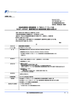
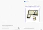
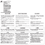
INB-F50880873c-JEC
取扱説明書 / INSTRUCTION MANUAL / 操作使用说明书
125∼250Aフレーム 表面形
Frames 125A to 250A Front Mounting type
125~250A 框架 表面形
富士オートブレーカ・富士漏電遮断器
FUJI AUTO BREAKER・FUJI EARTH LEAKAGE CIRCUIT BREAKER
富士塑壳断路器・富士漏电断路器
安全上のご注意
Before installation, wiring, operation, maintenance and inspection of the
device, be sure to read the operating instructions carefully to ensure
proper operation. Care should be taken that the operating instructions will
be furnished to the maintenance supervisors of final users.
Safety precautions items are classified into “ Warning ” and “ Caution ”.
: Incorrect handling of the device may result in death or
serious injury.
取付け,配線工事,操作および保守・点検を行う前に,取扱説明書,
「取扱と保守マニュ
アル」などを良くお読みの上,正しくご使用ください。
また取扱説明書などが最終の使用責任者の元に届くよう,ご配慮願います。
「取扱と保守マニュアル」は支社,営業所にご請求ください。
● ここでは,安全注意事項のレベルを「警告」および「注意」として区分してあります。
警告 : 取扱いを誤った場合に,死亡または重傷を受ける可能性があります。
注意
: 取扱いを誤った場合に,中程度の傷害や軽傷を受ける可能性,あるいは
物的損害が発生する可能性があります。
なお, に記載された事項でも,
状況によっては重大な結果に結びつく
注意
可能性があります。
警告
● 取付け,取外し,配線作業および保守・点検は,必ず上位遮断器を切って行ってください。
感電および短絡による火傷のおそれがあります。
● 2か所の裸充電部に同時にさわることは絶対しないでください。
感電しても漏電遮断器は動作しません。
I L+ I g
IL
IL+I g
IL
Ig
漏電遮断器
ELCB
漏电断路器
注意
● 開梱時に,損傷,変形のあるものは使用しないでください。
● 取付け,電気工事および保守・点検は専門知識を持つ有資格者が行ってください。
● 高温,多湿,じんあい,腐食性ガス,過度の振動・衝撃など異常な環境に設置しないで
ください。火災,誤動作などのおそれがあります。
● 自動的に遮断した場合は,原因を取り除いてからハンドルを投入(ON)してください。
火災のおそれがあります。
● 端子締付状態などの定期点検を行ってください。誤動作のおそれがあります。
● ゴミ,コンクリート粉,鉄粉など異物が機器内部に入らないように施工してください。
接触不良や釈放不良および誤動作などのおそれがあります。
● 許可されていない内容での改造を行わないでください。
● 製品を廃棄する場合は,産業廃棄物として取り扱ってください。
● アルミ端子,導体のブレーカ端子への直接接続は行わないでください。
● 本体に記載の定格電圧,定格電流の範囲内で使用してください。
定格外の使用は故障,不要動作の原因となります。
● 電源側と負荷側の表示のあるものは,間違いなく結線してください。
火災,故障の原因となります。
● 漏電遮断器は電子部品を使用していますので,内部に結露が発生しますと不要動作など
の弊害が生じます。温度変化の激しい場所でのご使用や保管を避けてください。
また,高調波成分を含んだ回路の場合,遮断器の零相変流器(ZCT)が鉄損等により過熱
しますので,負荷機器の漏れ電流の歪を10kHz以下で,且つ3A以下でご使用ください。
安全注意事项
在进行安装,接线施工、操作及维护、维修前,请仔细阅读使用说明书,正确使用。
另外,根据需要,请将本使用说明书交给最终使用负责人。
● 在此使用说明书里,将安全注意事项的级别分为
:「警告」和「注意」两个等级。
警告 :误操作时,有可能造成死亡或重伤。
:误操作时,有可能造成中等程度的残疾或轻伤。
注意 也有可能发生物质损伤事故。
注意
而标有 的事项,根据情况,也会造成严重后果。
警告
● 在安装、拆卸、接线施工及维修时,必须切断上位断路器。否则会触电,
或因短路造成烧伤。
● 请务必不要同时触摸两处充电部。否则,即使触电,断路器也不动作。
: Incorrect handling of the device may result in minor
injury or physical damage.
Even some
items may also result in a serious accident.
● Turn off the upstream circuit breaker prior to installation, removal,
wiring, maintenance or inspection to prevent electric shocks and
burns due to short-circuit.
● Do not touch two live lines at the same time. Earth leakage circuit
breaker does not operate even if an electric shock occurs.
● Do not use one found damaged or deformed when unpacked.
● Installation, electric work, maintenance and inspection of the device
should be performed by qualified engineers having special knowledge.
● Do not install the device in a place of environment with high
temperature, humidity, dust, corrosive gases, excessive vibration/shock,
etc. to prevent fire accidents and malfunction of the device.
● When the circuit breaker trips of itself, remove the cause and turn the
handle on. Or else, it may lead to fire accident.
● Make sure that terminals are fully tightened periodically to prevent
malfunction.
● Care should be taken to prevent entry of foreign objects such as dust,
concrete chips, iron powder, etc. or it may result in poor contacts,
defective release unless it is permitted.
● Do not modify the device unless it is permitted.
● When the device is to be disposed of, it should be handled as an
industrial waste.
● Do not connect aluminum terminals and conductors to the breaker
directly.
● Use the breaker in a range of the rated voltage and current shown on
the name plate. Or, the breaker may malfunction.
● Make connection on line side and load side in acorrect manner.
Or, fire accident may or malfunction may occur.
● Earth leakage circuit breaker does not operate normally whendew is
generated. Do not use and storage the earth leakagecircuit breaker
in the place where the temperature changeis extreme. Moreover,
since ZCT of a breaker may be overheatedin the case of the circuit
containing harmonics, use the breakerunder the conditions for the
distortion of the leakage currentis 10kHz or less and three ampere or less.
注意
● 开箱时,请确认产品是否有破损和变形。如有,请勿使用。
● 安装、电气工事及维护、维修作业,务必让有专门知识的人员进行。
● 请不要将此产品安置在高温,多湿,尘埃,腐蚀性气体,过度的振动和冲
击等异常环境中。否则,有发生火灾和误动作的可能性。
● 自动断路时,请先查清原因后再投入手柄(ON),否则,有可能导致火灾。
● 请定期检查端子的紧固状态,以防止误动作。
● 请注意不要使灰尘、水泥粉、铁粉等异物掉入机器内部,否则有可能引起
接触不良、释放不良和误动作。
● 在没有得到许可时,请不要对机器进行改造。
● 废弃此产品时,请按产业废弃物处理。
● 请不要直接接触铝端子,导体的断路器端子。
● 请在本体所记载的额定电压,额定电流范围内进行使用。否则,有可能
引起故障和不必要的动作。
● 对于有特别说明的电源侧和负荷侧,请正确接线。否则有可能发生火灾
和故障。
● 由于漏电断路器使用了电子部件,如果内部发生结露的话,有可能发生
不必要的动作。应避开在温度变化剧烈的场地的使用及保管。另外,
对于含有高次谐波成分的电路,断路器的零相变流器(ZCT)因铁损等
而过热,因此请使用漏电流失真在10kHz以下并且在3A以下的负荷机器。 1. 確認
1.确认
1. Check
本ブレーカを開梱したら,輸送中に損傷した個所が無いか
どうか点検願います。同梱包部品を表1にて確認願います。
表1 梱包部品 Table 1 Parts in a package
ブレーカの形式
Breaker type
断路器的型号
BW125JAGU
BW125RAGU
EW125JAGU
EW125RAGU
梱包部品
Parts in the packing
共通部品 Common part
Upon unpacking the breaker,verify no damage in transport.
Please also confirm that the specifications of the parts
match those in Table 1.
表1 捆包部件
捆包部件
ねじ端子専用部品 Only for screw terminal 螺钉端子专用部件 平形端子専用部品 Only for flat terminal 平型端子专用部件
通用部件
取付ねじ
Mounting screw
安装螺钉
M4×70 2本
M4×70 2pcs.
M4×70 2条
十字穴付なべねじ
Cross recessed head screw
十字槽头螺钉
M8×16 6本
M8×16 6pcs.
M8×16 6条
相間バリア
Interphase barrier
相间隔板
BW9BPCA 4枚
BW9BPCA 4pcs.
BW9BPCA 4枚
平座金
Plain washer
平垫圈
M8 6枚
M8 6pcs.
M8 6枚
端子カバー
Terminal Cover
端子盖
BW9BTCA 2個
BW9BTCA 2pcs.
BW9BTCA 2个
ばね座金
Spring washer
弹性垫圈
M8 6枚
M8 6pcs.
M8 6枚
端子カバー取付ねじ M3×12 4本
Terminal Cover Screw M3×12 4pcs.
端子盖安装螺钉
M3×12 4条
BW250EAGU
BW250JAGU
BW250RAGU
EW250JAGU
EW250RAGU
M4×70 4本
M4×70 4pcs.
M4×70 4条
六角穴付ボルト
M8×16 6本
Hexagon socket head cap bolt M8×16 6pcs.
M8×16 6条
六角槽螺栓
相間バリア
Interphase barrier
相间隔板
BW9BPGA 4枚
BW9BPGA 4pcs.
BW9BPGA 4枚
平座金
Plain washer
平垫圈
M8 6枚
M8 6pcs.
M8 6枚
端子カバー
Terminal Cover
端子盖
BW9BTGA 2個
BW9BTGA 2pcs.
BW9BTGA 2个
ばね座金
Spring washer
M8 6枚
M8 6pcs.
M8 6枚
弹性垫圈
端子カバー取付ねじ M3×12 4本
Terminal Cover Screw M3×12 4pcs.
端子盖安装螺钉
M3×12 4条
3. 接続
图1 (125-250AF)
付属カバーねじ
Accessory cover screw
附属外壳螺钉
(9) このブレーカーは,端子カバー付でのみULの承認を得
てます。
配線後は,必ずねじにより固定してください。
締付トルクは0.5∼0.6 N・mとしてください。
ばね座金
Spring washer
弹性垫圈
M8 6枚
M8 6pcs.
M8 6枚
ナット
Nut
螺母
M8 6個
M8 6pcs.
M8 6个
3.1 连接时的注意事项
(1) 请确认电压没有印加在连接电线、导电部件以及断路器上。
(2) 电线请按照NEC(National Electric Code∶美国电气工
程规定)或者CEC(Canadian Electrical Code Part 1∶
加拿大电气工程规定)连接。
(3) 连接电线请使用75℃铜线。此外,请使用UL认定电线或
者CSA认定电线。
(4)请对连接电线,压接端子和导电部件进行平行安装。
(图1)
(5) 因为附带了相间隔板,请将电源、负荷侧相间安装。
此外,当紧贴安装125-250AF的断路器时,请在断路器之
间安装相间隔板。当没有相间隔板时,请在压接端子或
导电部件的裸露充电部利用绝缘罩或胶带等进行绝缘,
或者安装端子罩(另卖品)。(图1)
(6) 当短路电流通过时,在电线间会发生非常大的电磁力,
因此请强固电线的支持力。
(7) 请定期拧紧端子螺钉。
(8) 请不要让燃弧气体排出口堵塞。
表2 電線のより線 Table 2 Number of strands connecting wires 表2 电线的绞线
密着取付 Side-by-side installation
紧贴安装
Fig.1
M8×22 6本
M8×22 6pcs.
M8×22 6条
M8 12枚
M8 12pcs.
M8 12枚
3.连接
(1) Confirm that no voltage is applied to the breaker, wire
and Bus.
(2) When connecting the wires,follow the instruction of
NEC (National Electric Code,USA) or CEC (Canadian
Electrical Code Part 1, Canada).
(3) For connecting, use the copper wire for 75℃.
Use the UL or CSA approved wires.
(4) Each connecting wire or crimp terminal,conductor
pole should be connected in pallarel as shown in the
Fig.1.
(5) Fit the attached interphase barriers between phases
on the line and the load side. When mounting
125-250AF breakers side by side, fit the interphase
barriers between breakers as shown in the Fig.1.
(6) Keep the connection of the wire tight sufficiently,
because the very large electromagnetic force will be
generated, when the short circuit current is applied.
(7) Perform the additional tightening of the terminal
screws periodicaly.
(8) Keep open the outlet of the arc gas.
相間バリア Interphase barrier
相间隔板
図1
六角ボルト
Hexagon head bolt
六角螺栓
平座金
Plain washer
平垫圈
断路器的安装,请使用一同捆包的安装螺钉。
3.1 Precaution for connecting
(1)接続電線・導体およびブレーカに電圧が印加されて
いないことをご確認ください。
(2)電線の接続は,NEC(National Electric Code:
米国電気工事規定)またはCEC(Canadian
Electrical Code Part 1:カナダ電気工事規定)に
従って接続してください。
(3)接続電線は,75℃銅線をご使用ください。なお,UL
認定電線またはCSA認定電線をご使用ください。
(4)接続電線,圧着端子や導体は,各極が並行となるよ
うに取付けてください。
(図1)
(5)相間バリアが付属しておりますので,電源,負荷側
相間に取付けてください。また125-250AFのブレ
ーカを密着取付けする場合は,ブレーカ間に相間
バリアを取付けてください。相間バリアが無い場合は,
圧着端子や導体の裸充電部に絶縁キャップやテー
ピングなどにより絶縁を施すか,または端子カバー
(別売品)を取付けてください。
(図1)
(6)短絡電流が流れますと,電線間に非常に大きな電磁力
が発生しますので,電線の支持を強固にしてください。
(7)端子ねじを定期的に増し締めしてください。
(8)アークガス排出口をふさがないでください。
M8 6個
M8 6pcs.
M8 6个
2.安装
Fix the breaker using mounting screws.
3. Connecting
3.1 接続時のご注意
ナット
Nut
螺母
※BW250EAGU-2P, BW250JAGU-2P, BW250RAGU-2Pはそれぞれ4個ずつご使用ください。
Note. Use 4pcs. of screws for BW250EAGU-2P, BW250JAGU-2P, BW250RAGU-2P.
请各使用4个BW250EAGU-2P,BW250JAGU-2P,BW250RAGU-2P。
2. Mounting
ブレーカの取付けは,同梱されている取付けねじを使用
して行なってください。
平座金
Plain washer
平垫圈
ばね座金
Spring washer
弹性垫圈
M8×22 6本
M8×22 6pcs.
M8×22 6条
M8 12枚
M8 12pcs.
M8 12枚
M8 6枚
M8 6pcs.
M8 6枚
六角ボルト
Hexagon head bolt
六角螺栓
※BW125JAGU-2P, BW125RAGU-2Pはそれぞれ4個ずつご使用ください。
Note. Use 4pcs. of screws for BW125JAGU-2P, BW125RAGU-2P.
请各使用4个BW125JAGU-2P,BW125RAGU-2P。
取付ねじ
Mounting screw
安装螺钉
2. 取付け
打开本断路器的包装后,请检查有无在运输途中损伤的地方。
同一包装中的部件请根据表1确认。
電線サイズ
Wire size
AWG or MCM (mm2)
电线尺寸
14-2AWG (2.1-33.6mm2)
より線の数
Number of strands
绞线的数量
7
1-4/0AWG (42.4-107.2mm2)
19
250-500MCM (127-250mm2)
37
(9) This breaker acquires of UL approved only with
Terminal Cover. Be sure to fix Terminal Cover by
Screw after wiring work.
(Tightening torque : 0.5 to 0.6 N·m)
端子カバー
Terminal Cover
端子盖
取付ねじ
Screw
安装螺钉
電源側,負荷側に装着してください。
Set LINE Side and LOAD Side
请在电源侧、负载侧安装。
(9)本断路器只有带端子盖的得到了UL的承认。
接线后请必须使用螺钉固定。
请使用0.5~0.6 N・m的紧固扭矩。
②
取外し/Removal/拆卸
ねじを外してください。
取外すときはツメを矢印方向に引きながら (①)
手前に引き抜いてください。(②)
Loosen the screws.
Pull out the terminal covers (①) while knocking
down the click (②) in the direction of the arrow.
①
取下螺钉
把突起部分按图中箭头方向放倒,(①)
然后向前抽出端子盖。(②)
3.2 ブロック端子の場合
3.2 Lug terminal
(1)端子への接続電線は,表3に示す接続可能電線サイズ
の電線をご使用ください。
(2)電線のより数は表2に従ってください。なお,多芯線の
接続はできません。
(3)ブロック端子には,サイズの異なった2種類の電線を
一緒に接続できません。
(4)電線は,半田固めしないでください。
(5)電線は,表3に示す締付トルクで締め付けてください。
3.3 ねじ端子の場合
(1) Use the connecting wire of the sizes listed in the Table 3.
(2) Follow the number of the strands of the wire indicated
in the Table 2. In addition, the multiconductor wire can
not be connected.
(3) To the Lug terminal two wires with which sizes differed
cannot be connected at the same time.
(4) Do not solder the end of the wire.
(5) Fasten the wire with the tightening torque indicated in
the Table 3.
3.3 Screw terminal
(1)端子への接続電線は,表3に示す電線サイズのものを
ご使用ください。
(2)電線は直接接続できませんので,表3に示す圧着端子
をご使用ください。
(3)端子ねじは,表3に示す締付トルクで締め付けてくだ
さい。
(4)接続導体は,表4に示すサイズのものをご用意くださ
い。
3.4 平形端子の場合
(1) Use the connecting wire of the sizes listed in the Table 3.
(2) Because wire cannot be connected directly to the
terminals, select crimp terminal shown in the Table 3.
(3) Fasten the connecting bolt with the tightening torque
indicated in the Table 3.
(4) Use the connecting bus bar of the sizes in the Table 4.
3.4 Flat terminal
(1)平形端子への接続電線は,表3に示す電線サイズの
ものをご使用ください。
(2)電線は直接接続できませんので,表3に示す圧着端子
をご使用ください。
(3)接続ボルトは,表3に示す締付トルクで締め付けてく
ださい。
(4)圧着端子を2個平形端子に接続する場合は,取付け面
との絶縁距離が不足することがありますので,テーピ
ングなどで絶縁強化してください。
(1) Use the connecting wire of the sizes listed in the Table 3.
(2) Because wire cannot be connected directly to the
terminals, select crimp terminal shown in the Table 3.
(3) Fasten the connecting bolt with the tightening torque
indicated in the Table 3.
(4) The case two crimp terminals are to be connected,
reinforce the insulating distance to the mounting
surface may be shorten, it needs to make insulate by
taping, etc.
3.2 滑块端子时
(1) 连接端子的电线请使用如表3所示可连接尺寸的电线。
(2) 电线的绞数请按照表2。此外,不可以连接多芯线。
(3) 滑块端子上不可以一起连接尺寸不同的2种电线。
(4)电线请不要用烙铁固定。
(5) 电线请如表3所示用紧固扭矩拧紧。
3.3 螺钉端子时
(1)连接端子的电线请使用如表3所示的电线尺寸。
(2)电线不能直接连接,请使用如表3所示的压接端子。
(3)端子螺钉请用如表3所示的紧固扭矩拧紧。
(4)连接导体请用如表4所示的尺寸。
3.4 平型端子时
(1)连接平型端子的电线,请使用如表3所示尺寸的电线。
(2)电线不能直接连接,因此请使用如表3所示的压接端子。
(3)连接螺栓请用如表3所示的紧固扭矩拧紧。
(4)将压接端子连接在2个平型端子上时,因为有时候到安装
面的绝缘距离会不够,请用胶布等强化绝缘。
表3 電線サイズと締付トルク
Table 3 Connectable wire size and tightening torque 表3 连接电线的尺寸和紧固扭矩
ブレーカの形式
Breaker type
断路器的型号
定格電流 接続電線サイズ
Rated
Wire size
Current 连接电线尺寸
额定电流
*1
15A
14 AWG
( 2.1mm2 )
20A
32A
12 AWG
( 3.3mm2 )
10 AWG
( 5.3mm2 )
8 AWG
( 8.4mm2 )
40A
8 AWG
( 8.4mm 2 )
50A
8 AWG
( 8.4mm 2 )
30A
BW125JAGU
BW125RAGU
EW125JAGU
EW125RAGU
60A
70A
75A
80A
90A
100A
125A
BW250EAGU
BW250JAGU
BW250RAGU
EW250JAGU
EW250RAGU
6 AWG
( 13.3mm2 )
4 AWG
( 21.1mm2 )
4 AWG
( 21.1mm2 )
4 AWG
( 21.1mm2 )
3 AWG
( 26.7mm2 )
3 AWG
( 26.7mm2 )
1 AWG
( 42.4mm2 )
適合圧着端子と圧着工具
Applicable crimp terminals and tools
JST (UL File No.E42024)
圧着端子
Terminal
压接端子
R2-8
5.5-S8
R5.5-8
8-8NS
R8-8
14-8NS
14-S8
R14-8
22-S8
R22-8
CB22-S8
38-S8
125A
1 AWG
( 42.4mm2 )
38-S8
R38-8
150A
1/0 AWG
( 53.5mm2 )
60-S8
R60-8
175A
2/0 AWG
( 67.4mm2 )
70-8
200A
3/0 AWG
( 85.0mm2 )
CB80-S8
225A
4/0 AWG
(107.2mm 2 )
CB100-S8
250A
250kcmil
(127mm2 )
CB150-S8
注記 *1 接続電線は75℃電線を使用
*2 圧着端子製造会社:JST=日本圧着端子製造株式会社
NICHIFU=株式会社ニチフ
DST=大同端子製造株式会社
圧着工具
Tool
压接工具
YHT-2210,YA-1
YA-2,YAT-1A
YAT-2A,YAD-1A
YAD-2A,YA-4
YAT-4A,YAD-4A
BCT-0514
YHT-8S,YA-4
YA-5,YAT-4A
YAD-4A,YPT-60-21
YPT-150-1,BCT-0514
BCT-860,BCT8150
YF-1,E-4,YET-60-1
YET-150-1
YA-4,YA-5,YAT-4A
YAD-4A,YPT-60-21
YPT-150-1,BCT-0514
BCT860,BCT8150
YF-1,E-4,YET-60-1
YET-150-1
YA-5,YPT-60-21
YPT-150-1
BCT-860
BCT-8150
YF-1,E-4
YET-60-1
YET-150-1
YA-5,YPT-60-21
YPT-150-1,BCT-860
BCT-8150,YF-1,E-4
YET-60-1,YET-150-1
YA-5,YPT-60-21
YPT-150-1,BCT-860
BCT-8150,YF-1
E-4,YET-60-1
YET-150-1
YET-300-1,YET-300N
YPT-150-1
BCT-8150
YF-1,E-4
YET-150-1
YET-300-1
YET-300N
适合的压接端子和压接工具 *2 締付トルク Tightening torque 紧固扭矩
NICHIFU (UL File No.E44245)
圧着端子
Terminal
压接端子
R2-8
R3.5-8
R5.5-8
圧着工具
Tool
压接工具
NH1,NH9
NH61
NH1,NH9
R5.5-8
R8-8
NH1,NH9
NOP60
NOM60
R14-8S
R14-8
NH9,NOP60
NOM60
NOP150H
NOM150
R22-8S
R22-8
CB22-8S
R60-8
CB60-8
CB60-8S
R70-8
圧着端子
Terminal
压接端子
2-8
2-B8
3.5-8
5.5-8
5.5-8
圧着工具
Tool
压接工具
5N18,214A
REC-14A
14-S8
14-8
214A,9H-60
9H-150
REC-14A
REC-60F
REC-150
NOP60,NOM60
NOP150H
NOM150
ねじ端子・平形端子
Screw/flat
terminal
螺钉端子・平型端子
ブロック端子
Lug terminal
滑块端子
MINI12
5N18,214A
DH-1B,AC-5ND
REC-14A
5N18,214A
DH-1B
AC-5NC
REC-14A
8-8
22-S8
22-8
CB22-8
R38-8S
R38-8S
R38-8
DST (UL File No.E74917)
50 lb.-in.
(5.8N・m)
50 lb.-in.
(5.8N・m)
93 lb.-in.
(10.5N・m)
200 lb.-in.
(23N・m)
9H-60
9H-150
REC-60F
REC-150
38-S8
NOP60,NOM60
NOP150H
NOM150
NOF300
NOM2500A
NOM3000
NOH300K
38-S8
CB60-8
60-8
NOP150H
NOM150,NOF300
NOM2500A
70-8
NOM3000
NOH300K
−
−
Notes : *1 167℉(75℃) Copper wire
*2 Crimp terminal manufacturer :
JST= Japan Solderless Terminal MFG Co.,Ltd.
NICHIFU=Nichifu Terminal Co.,Ltd.
DST=Daido Solderless Terminal MFG Co.,Ltd.
9H-60
9H-150
REC-60F
REC-150
9H-60
9H-150
12K-1
Number12A
REC-60F
REC-150
9H-150
REC-150
CB80-8
9H-150
12K-1
CB100-8
Number12A
REC-150
CB150-8
注记 *1 连接电线使用75℃电线
*2 压接端子制造公司∶JST=日本压接端子制造株式会社
NICHIFU=NICHIFU株式会社
DST=大同端子制造株式会社
表4 端子部寸法と接続導体
Table 4 Dimensions of terminal and copper bus
表4 端子部分尺寸和连接导体
フレーム
Frame
框架
端子部寸法
Dimensions of terminals
端子部尺寸
mm*
形式
Type
型号
8.5
ø9
10
BW125JAGU
BW125RAGU
EW125JAGU
EW125RAGU
17
8
24
t≦6
25以下
25 or less
M8×16
11
35
BW250EAGU
BW250JAGU
BW250RAGU
EW250JAGU
EW250RAGU
25.5
ø9
8
24
10.5
250A
16.5以下
16.5 or less
M8×16
30
125A
接続導体
Copper bus
连接导体
mm*
t≦6
* x0.0394=inch 3P3E
1
電源側
Line side
电源侧
3
5
過負荷短絡保護素子
Overcurrent tripping device
过载短路保护元件
メガテスト切替スイッチ
Dielectric test switch
耐压SW
2
1
ZCT
T
LINE
I n trip
n
(A)
0.100 0.300 0.500 1.000
-0
- 200
- 500 (ms)
- 1000
t
push
to trip
T
test
LOAD
2
4
負荷側
Load side
负荷侧
6
漏電引外し装置
Earth leakagetripping device
漏电检测电路
耐電圧試験
Dielectric tests
绝缘耐压试验
4
3
4. その他の注意事項
4. OTHER CAUTIONS
4.其它注意事项
● 漏電遮断器において相間の絶縁抵抗測定および耐電圧
● Measurement of insulation resistance between phases
and the dielectric strength test can be performed by
pressing and turning the Dielectric test switch. Return
the Dielectric test switch after the test is completed.
● Before operating the Dielectric test switch, press the
trip button to trip the breaker.
● Ground the ground terminals of electrical devices.
● Press the test button of Earth leakage circuit breaker
at least once a month to perform an operation check.
● Do not use transceivers from earth leakage circuit
breaker within one meter. Otherwise, the breaker may
malfunction.
● Detach the accessory cover screw only when you
install accessories.
● Refer to accessory instruction manual for their installation.
● 在将本体的耐压按钮按下的状态下,可以对漏电断路器实
試験は,本体のメガテスト切替スイッチを押し回した状態
で行うことができます。試験後はメガテスト切替スイッチ
を戻してください。
● メガテスト切替スイッチの操作は,トリップボタンを押し
ブレーカ本体をトリップ状態にして行なってください。
● 電気機器のアース端子は,必ず接地してください。
● 漏電遮断器は,月に1回程度テストボタンを押して,動作
確認を行ってください。
● トランシーバー等の無線機を使用する場合は,本器から
1m以上離れて使用ください。
● 付属カバーねじは,付属品の着脱時のみ操作してくださ
い。
● 付属品を取付ける場合は,付属品の取扱説明書をご覧く
施相间绝缘电阻测定及耐压试验。
试验结束后,请将耐压按钮复原。
● 请按下解扣按钮,将断路器本体置于解扣状态,再进行耐压
按钮的操作。
● 电气机器的接地端子请务必接地。
● 对于漏电断路器,请按每月一次的频度按动试验按钮确认
动作。
● 在使用无线电收发机等双向无线电设备时,请在离开本机
器1米以外使用。
● 关于顾客可自行安装附属品的机种的附属外壳螺钉,请仅
在装卸时进行操作。
● 安装附属品时,请参阅附属品安装使用说明书。
ださい。
器具事業部
〒103-0011 東京都中央区日本橋大伝馬町5番7号
(三井住友銀行人形町ビル)
TEL (03)
5847 - 8060
FAX(03)
5847 - 8182
URL http://www.fujielectric.co.jp/fcs/
Mitsui Sumitomo Bank Ningyo-cho Bldg., 5-7, Nihonbashi
Odemma-cho, Chuo-ku, Tokyo 103-0011, Japan
Phone : +81-3-5847-8060
Fax
: +81-3-5847-8182
URL http://www.fujielectric.co.jp/fcs/eng/
日本国东京都中央区日本桥大传马町 5 番 7 号
三井住友银行人形町 Bldg.
邮编 103-0011 电话 +81- 3- 5847- 8060
传真 +81- 3- 5847- 8182
URL http://www.fujielectric.co.jp/fcs/