1
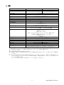
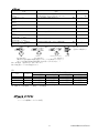
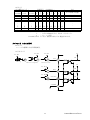
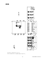
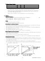
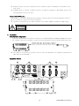
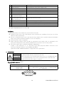
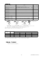
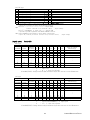
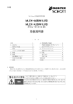
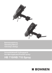
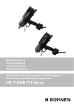
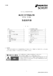
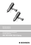
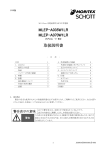
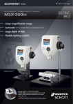
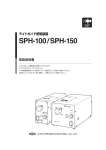
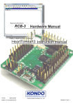
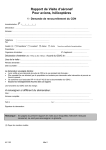
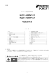
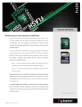
日本語
MG-Wave 定電流照明 MCEP 用電源
MLEP-A035W3LRD
MLEP-A070W3LRD
オプション –KE/-AE/-AC 含む
取扱説明書
目次
1. はじめに
使用上の注意
保証
パッケージ内容の確認
2. 特徴
3. 設置
基本構成について
各部の名称と働き
設置
目
次
1
1
2
2
3
3
4
4
4
5
4. 外部装置との接続
外部信号接続コネクタについて
出力コネクタについて
5. メンテナンスについて
故障かな?と思ったら
6. 仕様
オプション
外形寸法
《MEMO》
《付録》
5
5
7
7
7
8
9
12
13
14
1. はじめに
製品の安全な使用のためこの取扱説明書を必ずお読みになり、ご理解のうえご使用ください。またお読み
になった後は、本書をいつでも見られるところに保管してください。
以下の警告表示は、本書の中で使用されているものです。
表示の内容をよく理解してから、本書をお読みください。
この表示の注意事項を守らないと、軽傷や中程度の障害を負ったり、死亡や
重症に至るおそれがある内容、または重大な物的損害を受けるおそれがあ
る内容を示しています。
警告表示の意味
警告
様式 : HJDS00030A
1
A09634B5000501B-003
使用上の注意
警告
・
・
・
・
・
・
・
・
以下の内容をご確認のうえ、ご使用ください。
本製品を他の機器と組み合わせて使用する場合、組み合わせる機器との適合はお客様にて確認して
ください。
本製品を他の機器と組み合わせて使用する場合、そのシステムが適合すべき規格・法規・規制はお客
様にて確認してください。
本製品を他の機器と組み合わせて使用する場合、システムの中で本製品が意図した用途に対して適
切に配電・設置・使用されていることはお客様にて確認してください。
システム全体として確実な安全対策が施されていない場合、生命や財産に重大な危険を及ぼす可能
性のある設備に本製品を使用しないでください。
本製品に水がかからない場所に設置してください。
もし何らかの異物が製品に付着した場合、乾いた布で完全にふき取ってください。
保守部品の定期的な点検および交換をしてください。
不具合が発生した場合、分解することなく弊社まで修理を依頼してください。
その他の注意事項
・ 本製品を廃棄する場合、産業廃棄物として各地域の法令に基づいて処理してください。
・ 寸法と重量などの数値は参考値です。
・ 本製品(添付品・オプション品)の仕様は、改良や他の理由により予告なく変更になる場合があります。
・ 不明な点は、必ず弊社までお問い合わせください。
保証
保証期間
本製品の保証期間は、納入後 1 年間となります。取扱説明書に記載された製品の正しいご使用方法にて
購入日より 1 年以内に故障が発生した場合に限り、無償にて修理いたします。
保証範囲
保証期間中に、製品に弊社の責による不具合が発生した場合は、無償にて故障部分の交換または修理
を実施いたします。ただし、以下の場合は除外されます。
・
・
・
・
・
・
・
・
出荷当時の技術水準では予見できなかった場合
本製品以外の原因による場合
弊社以外による改造または修理による場合
本来の使い方以外の使用による場合
落下や衝撃など取り扱いが不適切なために発生した場合
出張修理の場合
天災や公害など弊社の責ではない原因による場合
弊社に不具合の現象を確認する機会がない場合
本製品に関連する直接的または間接的損害については、いかなる責任も負いかねます。また保証の範囲
は、製品の単価を超えないものとします。なお、上記は日本国内での取引および使用を前提といたします。
海外での取引および使用については弊社までお問い合わせください。
様式 : HJDS00030A
2
A09634B5000501B-003
パッケージ内容の確認
部品名
数量
単位
備考
本体
1
個
-
ACコードセット
1
本
※
取扱説明書
1
冊
本書
※ ご購入時の型番の接尾辞により、『-100V』には『MC-AC100A-2.0M』が、『-200V』には
『MC-AC200A-2.0M』が添付されております。電源接続前に、主電源コードが使用される
国の法律・規格を満足し、電源電圧・温度の仕様条件に合っているか確認してください。
5 ページ: 設置 8 ページ: 仕様 9 ページ: オプション 参照
2. 特徴
使用可能な照明
モリテックス製 MG-Wave の照明のうち、以下の照明がご使用になれます。
※1
MLEP-A035W3LRD : 3 ピン / 0.35 [A] 照明
MLEP-A070W3LRD : 3 ピン / 0.70 [A] 照明
出力
3 チャンネルの出力が可能です。
※ 各チャンネル独立でコントロール可能です。
マニュアル調整機能
前面パネルの出力調整スイッチで出力を調整し、接続された LED 照明を調光することが可能です。
※ 各チャンネル独立でコントロール可能です。(SEPA 時)
※ MANU/REMO スイッチが、MANU の時のみ有効です。
※ COARSE で粗調整が、FINE で微調整が可能です。
※ 0,1,・・・・,E,F は 16 進数です。
※ (COARSE, FINE)が(0,0)で MIN、(F,F)で MAX になります。
※ (0,0)から(0,5)程度まで、出力しない範囲があります。
リモート調整機能
後面パネルの外部信号接続コネクタに8ビットのデジタル信号を入力する事で出力を調整し、接続された
LED 照明を調光することが可能です。
※ 各チャンネル独立でコントロール可能です。(SEPA 時)
※ MANU/REMO スイッチが、REMO の時のみ有効です。
コンビネーション機能
前面パネルの COMB 調整スイッチまたは CH1 の8ビットデジタル信号により、設定した出力電流比率を変
えずに、接続された LED 照明を 3 チャンネル同時に調光することが可能です。
※ SEPA/COMB スイッチが、COMB の時のみ有効です。
※ 出力電流比率は、MANU/REMO に関係なく、前面パネルの CH1~CH3 の出力調整スイッチにて設
定します。
※ MANU 時、前面パネルの COMB 調整スイッチにて調整できます。
※ REMO 時、CH1 の8ビットデジタル信号にて調整できます。
様式 : HJDS00030A
3
A09634B5000501B-003
出力 ON/OFF 機能
外部コネクタに信号を入力する事により、接続されたLED照明を消灯できます。
※ 各チャンネル独立でコントロール可能です。
※ MANU/REMO、SEPA/COMB に関係なく動作します。
※1
指定された照明以外は接続しないでください。
警告
3. 設置
基本構成について
・ 本装置と MCEP 照明を接続することでご使用になれます。 3 ページ:特徴 参照
・ 外部信号接続コネクタに信号を接続してご使用になれます。
※ オプションで、外部接続ケーブル・照明用中継ケーブルもあります。(MC-EXC-02, M-RCB3**L)
各部の名称と働き
様式 : HJDS00030A
4
A09634B5000501B-003
① 電源スイッチ
『 I 』側にすると、電源が入ります。
② パワーインジケータ
電源が入っている時に点灯します。
③ SEPA/COMB スイッチ
出力調整のセパレートとコンビネーションを設定します。
④ MANU/REMO スイッチ
出力調整のマニュアルとリモートを設定します。
⑤ コンビネーション調整スイッチ
コンビネーションの出力を調整します。
⑥ 出力調整スイッチ
マニュアルの時に、出力を調整します。
⑦ 照明用出力コネクタ
照明を接続します。
⑧ 外部信号接続コネクタ
外部機器を接続するためのコネクタです。
⑨ AC インレット
AC ケーブルを差し込みます。
⑩ 側面空気穴
冷却用の空気穴です。
⑪ ゴム足
オプションの取付ブラケットを使用するときは外します。
⑫ チャンネル表示
表示の下にチャンネルごとの部品が配置されています。
※ 図は MLEP-A070W3LRD のものです。
※ ⑩は MLEP-A035W3LRD にはありません。
設置
ゴム足を下にした水平設置。
※ 設置後、本体周囲に 10mm 以上の空間を確保してください。
※ 電源スイッチの ON/OFF が容易に行える場所、あるいはインレットまたはプラグが容易に取り外せる場
所に設置してください。
※ 感電保護 : クラスⅠ機器。
※ 使用する際には、入力する AC 電圧と使用する国や地域の規格に適合した適切な電源コードをご使
用ください。
※ 以下の構成にて EU 指令/EN 規格に適切に適合することができます。
長さ:3m 以下
端子:L/N/PE
クラスⅠ機器用プラグにて保護接地端子に接続
オプションの MC-AC200A-2.0M は上記規格に適合しております。
4. 外部装置との接続
警告
・接続する機器の一次側の回路から強化絶縁以上で分離された SELV 回路
以外は接続しないでください。
・外部信号接続ケーブルは必ずシールド線を使用し、長さは 2 m 以下
を推奨します。(オプション: MC-EXC-02)
・過大な入力や過負荷はしないでください。
外部信号接続コネクタについて (EXT)
型式
本体側コネクタ
HDAB-15P(05)(オス)
(HRS製)
固定ネジ M2.6
様式 : HJDS00030A
外部ケーブル側コネクタ
HDAB-15S(05) : コネクタ(メス) (HRS製)
HDA-CTH : コネクタケース (HRS製)
または 同等品
5
A09634B5000501B-003
ピンアサイン
№
1
2
3
4
5
6
7
8
※1
名 称
№ 名 称
9 COMMON (+)
※1
8bitデジタル入力 20 (LSB)
10 出力ON/OFF信号(入力)
※2
8bitデジタル入力 21
2
11 NC
8bitデジタル入力 2
※3 12 NC
8bitデジタル入力 23
13 NC
8bitデジタル入力 24
5
14 NC
8bitデジタル入力 2
6
15 NC
8bitデジタル入力 2
8bitデジタル入力 27 (MSB)
5 V から 24 Vに対応しています。
・ 使用中の入力変動は行わないでください。
※2 ”L”入力時 ・・・・・・・・・・・・・・・・・・・・・・・・・・・ 出力OFF
電流 COMMON 5 V時 : 1 mA 、 COMMON 24 V時 : 6 mA
”H”(COMMON)入力またはオープン時 ・・・・・ 出力ON
・ MANU/REMOに関係なく動作します。
・ オープンコレクタ入力が可能です。
※3 REMOのみ有効です。(出力の状態については真理値表を参照)
・ ”L”入力時 1回路あたりの電流
COMMON 5 V時 : 1 mA 、 COMMON 24 V時 : 6 mA
・ オープンコレクタ入力が可能です。
真理値表
出力調整スイッチ
COARSE
×
×
0
0
0
:
:
F
F
F
FINE
×
×
0
1
2
:
:
D
E
F
外部信号 COMMON +
出力
Bit Bit Bit Bit Bit Bit Bit Bit
出力(照明)の状態
27 26 25 24 23 22 21 20
× × × × × × × ×
出力OFF
× × × × × × × ×
出力ON
L
L
L
L
L
L
L
L
MIN出力
L
L
L
L
L
L
L
H
L
L
L
L
L
L
H
L
:
:
:
:
:
:
:
:
:
:
:
:
:
:
:
:
:
:
H
H
H
H
H
H
L
H
H
H
H
H
H
H
H
L
H
H
H
H
H
H
H
H
MAX出力
H
: High(COMMON)入力 または 入力オープン
L
: Low 入力
×
: H ・ L 任意
(COARSE,FINE) が (0,5) 程度まで点灯しない範囲があります。
出力
ON/OFF
L
H
H
H
H
:
:
H
H
H
入力
入力回路例
5 V - 24 V
5V
COMMON
A
A
A
LSB
9
47k
3.9k
1
5V
Relay
Photo-coupler
Transistor
47k
A
MSB
3.9k
5V
8
47k
A
様式 : HJDS00030A
6
ON/OFF
3.9k
10
A09634B5000501B-003
出力コネクタについて (MG-Wave の MCEP 照明用、各チャンネル共通: OUT1, OUT2, OUT3)
型式
本体側出力コネクタ
SMP-03V-BC (JST製)
照明側コネクタ
SMR-03V-B (JST製) または 同等品
ピンアサイン
MLEP-A035W3LRD
№ 名 称
1 NC
2 電流出力 (+)
3 電流出力 (-)
※1 出力電圧は 5.5 [V] 以下です。
オプション: M-RCB3**L
※1
※1
MLEP-A070W3LRD
№ 名 称
1 電流出力 (+)
2 NC
3 電流出力 (-)
※1 出力電圧は 5.5 [V] 以下です。
オプション: M-RCB3**L
※1
※1
5. メンテナンスについて
・お手入れをする時は、必ず電源を切り、外部機器との接続を全てはずして
から行ってください。
警告
・絶対に分解はしないでください。
・ 本体の汚れは、乾いた布でふき取ってください。
・ 汚れがひどい時は、布に薄めた中性洗剤を含ませ、かたくしぼってから汚れをふき取ってください。
故障かな?と思ったら
症状
原因
照明が点灯しない ・照明は正しく接続されていますか?
照明が暗い
・MANU/REMO の設定は正しいですか?
・出力調整はされていますか?
・外部機器が正しく接続されていますか?
ON/OFF しない
・外部機器が正しく接続されていますか?
様式 : HJDS00030A
7
対策
・照明を正しく接続してください
・MANU/REMO を確認してください
・調整してください
・外部機器を正しく接続してください
・外部機器を正しく接続してください
A09634B5000501B-003
6. 仕様
MLEP-A035W3LRD
MLEP-A070W3LRD
※1
AC 100 - 240 [V] (本体・ACインレット)
0.14/0.09 [A] typ.
0.25/0.14 [A] typ.
at AC 100 / 240 [V]
at AC 100 / 240 [V]
入力周波数
50/60 [Hz]
※2
入力突入電流
20 [A] max. at AC 100 [V]
40 [A] max. at AC 240 [V]
出力数
3チャンネル出力
出力電圧
Max 5.5 [V] (出力オープン時)
0.35 [A] (1チャンネルあたり) 0.70 [A] (1チャンネルあたり) ※3
出力電流
出力制御方式
定電流制御
出力形態
DC連続出力
出力調整機能
有り
マニュアル/リモート
セパレート/コンビネーション
出力可変範囲
0 - 100 [%]
リモートコントロール
有り
8ビットデジタル出力調整 / 出力ON/OFF制御
環境条件
屋内使用
最高高度 : 2000 m
温度 : 0 ℃ ~ 45 ℃
湿度 : 31 ℃ まで 80 % RH、40 ℃ で 50 % RH に線形に低下
主電源電圧変動が公称電圧の ± 10 % 以内
設置カテゴリ Ⅱ
汚染度2
保存温度/湿度
-20 ~ 75 [℃] / 20 ~ 85 [%RH] (結露なきこと)
設置方法
ゴム足を下にした水平設置
感電保護
クラスⅠ機器
冷却方式
自然空冷
IP 40 (EN 60529)
IP 30 (EN 60529)
※4
保護等級
外形寸法
W150×H75×D150 (突起部除く)
約
1.4 [kg]
質量
※5
欧州整合規格
Low Voltage: EN61010-1
EMC: EN55011, EN61000-3-2, EN61000-3-3, EN61000-6-2
※1 使用する際には、入力するAC電圧/電流と使用する国や地域の規格に適合した適切な電源コードをご使
用ください。(オプションにて製品に添付されているケーブルの型式をご確認ください。)
※2 コールドスタート時。
※3 指定電流の照明以外ご使用になれません。
※4 直径1mm(MLEP-A070W3LRDは2.5mm)以上の物体が内部に侵入しません。水の浸入に対して保護され
ていません。
※5 MLEP-A035W3LRD、MLEP-A070W3LRD及びオプション品は、上記ヨーロッパ規格への適合をCEマーキ
ングの宣言書にて宣言しております。また本体をCE適合にて使用する場合、CEマーキングに適合したAC
ケーブルをご使用ください。
(オプションのMC-AC200A-2.0MはCEマーキングに適合しております。)
型式
入力電圧
入力電流
様式 : HJDS00030A
8
A09634B5000501B-003
オプション
名称
CE適合 ○:Yes
×:No
※1 1m,2m:○
3m:× ※6
※2
○
型式
M-RCB3**L (3ピン用延長ケーブル)
照明用中継ケーブル
** 2桁は長さ (01=1m、02=2m、03=3m)
(別売り)
AC 200 Vケーブル
MC-AC200A-2.0M (2mのみ)
(別売り)
AC 200 Vケーブル
MC-AC200B-2.0M (2mのみ)
(別売り)
AC 100 Vケーブル
MC-AC100A-2.0M (2mのみ)
(別売り)
外部接続ケーブル
MC-EXC-02 (2m・片端バラ)
(別売り)
取付ブラケット
LBK-002 (底面取付タイプ)
(別売り)
8bitデジタル入力 KE改造
論理反転
(受注生産) 『-KE』
8bitデジタル入力 AE改造
COMMON極性反転
(受注生産) 『-AE』
8bitデジタル入力 AC改造
COMMON極性反転 および 論理反転
(受注生産) 『-AC』
※1 長さ違いはお問い合わせください。
※2 ※3
※4
※3
×
※4
×
※1
○
-
※5
○
※5
○
※5
○
アダプタ ( 国内のみ使用可 )
CE
<PS>E <PS>E/UL/CSA <PS>E
AC 250Vまで
AC 250Vまで AC 125Vまで
(使用する国や地域の規格に適合したケーブルを使用してください。)
(ケーブル仕様の詳細は別途弊社までお問い合わせください。)
※5 表1 参照 (型式末尾に-KE/-AE/-AC)
※6 3m延長ケーブルはCE適合外です
表1
出力(照明)の状態
8ビット論理
8ビットオープン ON/OFF論理
標準 (KC)
+
L 消灯
MAX点灯
L 消灯
KE
+
L 点灯
消灯
L 消灯
AC
H 消灯
MAX点灯
H 消灯
AE
H 点灯
消灯
H 消灯
※ COMMON +: 外部電源 +, COMMON -: 外部電源 -
※ 論理 H: 外部電源 +, 論理 L: 外部電源 -
Type
COMMON
ON/OFFオープン
点灯
点灯
点灯
点灯
オプション品 ピンアサイン
・KE タイプ
6 ページの標準ピンアサイン参照。
様式 : HJDS00030A
9
A09634B5000501B-003
・AC/AE タイプ
№
1
2
3
4
5
6
7
8
※1
名 称
№ 名 称
9 COMMON (-)
※1
8bitデジタル入力 20 (LSB)
10 出力ON/OFF信号(入力)
※2
8bitデジタル入力 21
11 NC
8bitデジタル入力 22
※3 12 NC
8bitデジタル入力 23
13 NC
8bitデジタル入力 24
14 NC
8bitデジタル入力 25
15 NC
8bitデジタル入力 26
8bitデジタル入力 27 (MSB)
COMMONに対し、各入力ピンは5 V から 24 Vに対応しています。
・ 使用中の入力変動は行わないでください。
※2 ”H”入力時 ・・・・・・・・・・・・・・・・・・・・・・・・・・・ 出力OFF
電流 H = 5 V時 : 1 mA 、 H = 24 V時 : 6 mA (電圧入力)
”L”(COMMON)入力またはオープン時 ・・・・・ 出力ON
・ MANU/REMOに関係なく動作します。
※3 REMOのみ有効です。(出力の状態については真理値表を参照)
・ ”H”入力時 1回路あたりの電流
H = 5 V時 : 1 mA 、 H = 24 V時 : 6 mA (電圧入力)
オプション品 真理値表
・KE タイプ
出力調整スイッチ
COARSE
×
×
0
0
0
:
:
F
F
F
FINE
×
×
0
1
2
:
:
D
E
F
・AC タイプ
出力調整スイッチ
COARSE
×
×
0
0
0
:
:
F
F
F
様式 : HJDS00030A
FINE
×
×
0
1
2
:
:
D
E
F
外部信号 COMMON +
出力
Bit Bit Bit Bit Bit Bit Bit
Bit
出力
出力(照明)の状態
ON/OFF 27 26 25 24 23 22 21 20
L
× × × × × × × ×
出力OFF
H
× × × × × × × ×
出力ON
H
H
H
H
H
H
H
H
H
MIN出力
H
H
H
H
H
H
H
H
L
H
H
H
H
H
H
H
L
H
:
:
:
:
:
:
:
:
:
:
:
:
:
:
:
:
:
:
:
:
H
L
L
L
L
L
L
H
L
H
L
L
L
L
L
L
L
H
H
L
L
L
L
L
L
L
L
MAX出力
入力
H
: High(COMMON)入力 または 入力オープン
L
: Low 入力
×
: H ・ L 任意
(COARSE,FINE) が (0,5) 程度まで点灯しない範囲があります。
外部信号 COMMON -
出力
Bit Bit Bit Bit Bit Bit Bit Bit
出力(照明)の状態
27 26 25 24 23 22 21 20
× × × × × × × ×
出力OFF
× × × × × × × ×
出力ON
H
H
H
H
H
H
H
H
MIN出力
H
H
H
H
H
H
H
L
H
H
H
H
H
H
L
H
:
:
:
:
:
:
:
:
:
:
:
:
:
:
:
:
:
:
L
L
L
L
L
L
H
L
L
L
L
L
L
L
L
H
L
L
L
L
L
L
L
L
MAX出力
H
: High入力
L
: Low(COMMON)入力 または 入力オープン
×
: H ・ L 任意
(COARSE,FINE) が (0,5) 程度まで点灯しない範囲があります。
出力
ON/OFF
H
L
L
L
L
:
:
L
L
L
入力
10
A09634B5000501B-003
・AE タイプ
出力調整スイッチ
COARSE
×
×
0
0
0
:
:
F
F
F
FINE
×
×
0
1
2
:
:
D
E
F
外部信号 COMMON -
出力
Bit Bit Bit Bit Bit Bit Bit Bit
出力(照明)の状態
27 26 25 24 23 22 21 20
× × × × × × × ×
出力OFF
× × × × × × × ×
出力ON
L
L
L
L
L
L
L
L
MIN出力
L
L
L
L
L
L
L
H
L
L
L
L
L
L
H
L
:
:
:
:
:
:
:
:
:
:
:
:
:
:
:
:
:
:
H
H
H
H
H
H
L
H
H
H
H
H
H
H
H
L
H
H
H
H
H
H
H
H
MAX出力
H
: High入力
L
: Low(COMMON)入力 または 入力オープン
×
: H ・ L 任意
(COARSE,FINE) が (0,5) 程度まで点灯しない範囲があります。
出力
ON/OFF
H
L
L
L
L
:
:
L
L
L
入力
オプション品 入出力回路例
・KE タイプ
6 ページの標準入出力回路例参照。
・AC/AE タイプ
5 V - 24 V
5 V - 24 V
A
Relay
A
Photo-coupler
5V
5 V - 24 V
A
LSB
47k
1
3.9k
Transistor
5V
5 V - 24 V
A
MSB
47k
8
3.9k
5V
5 V - 24 V
A
ON/OFF
47k
10
3.9k
COMMON
様式 : HJDS00030A
11
9
A09634B5000501B-003
外形寸法
図は MLEP-A070W3LRD のものです。
MLEP-A035W3LRD には、側面の空気孔は有りません。
様式 : HJDS00030A
12
A09634B5000501B-003
《 MEMO 》
7. その他
1. 装置および装置の部品は一般廃棄物として処理せずに、必ず分別してください。
2. 装置および装置の部品を廃棄する前に、処理方法または回収方法を必ず弊社までお問い合わせく
ださい。
3. 以下のシンボルは、廃電気・電子機器の分別回収を意味しています。装置および装置の部品は一般
廃棄物として処理しないでください。
4. 本装置は、2002/96/EC 指令(廃電気・電子機器の処理指令: Waste EIectrical and EIectronic
Equipment)に該当いたします。当指令においては、環境の保護・保存、人体の健康への保護、天然資源
の利用を慎重かつ合理的に行うことを最重要としています。本趣旨に基づき、取扱説明書による装置およ
び装置部品の廃棄によって、お客様が環境保全に対する責任を負うことをご承知ください。
5. 本装置は、2002/95/EC 指令(RoHS 指令)適合しております。
または
6. 装置内の危険物質は以下になります。
Lead (Pb): 15mg: Solder of Printed Wiring
Lead (Pb): 15mg: Solder of Printed Wiring
Lead (Pb): 15mg: Solder of Printed Wiring
Lead (Pb): 15mg: Solder of Printed Wiring
様式 : HJDS00030A
Boards
Boards
Boards
Boards
13
A09634B5000501B-003
《付録》
・不明な点はご相談ください。
補修部品の詳細やアフターサービスについてご不明な点は、お買い求めの販売店または弊社営業所に
遠慮なくお問い合わせください。
・修理を依頼される場合は、次のことをお知らせください。
機
種 : MLEP-A035W3LRD / MLEP-A070W3LRD
製 造 番 号 : 本体に記載
ご 購 入 日 :
年
月
日
故 障 状 況 : 出来るだけ詳しく
お名前(法人名または個人名)、ご住所、電話番号、e-mail アドレス
様式 : HJDS00030A
14
A09634B5000501B-003
English
Power source unit for MCEP Illuminators of MG-Wave constant current Illuminators
MLEP-A035W3LRD
MLEP-A070W3LRD
with or without suffix: -KE, -AE, -AC
INSTRUCTION MANUAL
Table of Contents
1. Introduction
Precautions for Correct Use
Warranty
Confirming Package Contents
2. Features
3. Installation
Basic System Configuration
Equipment Control
Installation
Table of Contents
15
15
16
16
17
17
18
18
18
19
-
4. Connections
External Signal Connector
Connector for Illuminator
5. Maintenance
Troubleshooting
6. Specifications
Optional Items
Dimensions
7. Others
《Appendix》
19
19
21
21
21
22
23
26
27
28
1. Introduction
Please read this instruction manual carefully, before starting operation. Keep this book for the whole
product lifetime, and store it in a place easily accessible.
The following warning symbol is used in this manual.
Be sure to fully understand the contents of the warning.
This warning marking indicates a potentially hazardous situation, which can
result in hazard to the operator or damage to the unit, if the directions of this
Instruction Manual are not followed.
Meanings of Warning Symbol
WARNING
様式 : HJDS00030A
15
A09634B5000501B-003
Precautions for Correct Use
WARNING
・
・
・
・
・
・
・
・
Use this product only after understanding contents of the following:
If using this product in combination with other apparatuses, please confirm the correctness/compatibility
of the connection with these external apparatuses (especially regarding insulation requirements).
If using this product in combination with other apparatuses, please confirm any standards, codes, or
regulations that apply to the combination of the apparatuses.
If using this product in combination with other apparatuses, please confirm that installation, connection
and use within the entire system is according to the specification of this product (as described in this
Instruction Manual) and according to those of all other apparatuses.
Never use the product for an application involving serious risks to life or property as long as the whole
system is not equipped with appropriate safety measures of the relevant safety category.
Please install this product in such a way that water cannot sprinkle into it.
Whenever some matter/dirt stuck to the product, please completely wipe it off, using a dry cloth.
This product needs periodical inspection and exchange of maintenance parts.
Whenever trouble occurs, please request repair to MORITEX, and do not dismantle the product by your own.
Other precautions
・ When a customer wants to scrap the product, the whole equipment has to be disposed as industrial
waste, according to laws and ordinances of the customer’s area.
・ Dimensions and Weights are reference.
・ Specifications of the product (or accessories or optional items) may be changed at any time based on
improvements and other reasons without any notice.
・ Please inquire to MORITEX about indistinct contents.
Warranty
The term of a warranty
The warranty of this product lasts for one year from the date of purchase. In case of product failure within
one year from the date of purchase, and there is no doubt on the correct utilization of the product,
according to this instruction manual the unit will be repaired at no charge.
Limitations of warranty
When inconvenience due to our responsibility occurs to a product during the warranty period, the part
that has trouble will be changed to a new part, or repaired, free of charge. But, if the cause of the trouble
fits to the following, the product is out of warranty.
・
・
・
・
・
・
・
・
The cause of the trouble is of such technical nature that could not be foreseen at the time of shipment.
The trouble is not caused by this product.
The trouble is caused by modification or repair by a person other than MORITEX.
The trouble is caused by unauthorized use, not conforming to this Instruction Manual.
The trouble is caused by the inappropriate handling such as a drop or a shock.
The trouble is repaired by MORITEX at on-site service.
The trouble is caused by a condition out of our responsibility such as a natural disaster or pollution.
The cause of the trouble can not be identified by MORITEX.
MORITEX shall not be responsible for indirect or consequential damages, in any way related to this
product. The responsibility of MORITEX for any act shall not exceed the price of this product. The
warranty is limited to business and use in Japan. Please inquire to MORITEX about warranty overseas.
様式 : HJDS00030A
16
A09634B5000501B-003
Confirming Package Contents
Part name
Quantity Unit
Notes
Main body
1
piece
-
Power Supply Cord Set
1
piece
※
Instruction Manual
1
book
This book
※ 『MC-AC100A-2.0M』 is attached to 『-100V』 model. 『MC-AC200A-2.0M』 is attached
to 『-200V』 model. (It depends on the suffix of the model that was purchased.)
Before connection to the power supply, please check the conformity of the specifications
of the Power Supply Cord Set with the laws and standards of your country as well as the
correct power and temperature rating.
Refer to Page 19: Installation, Page 22: Specifications, Page 23: Optional Items
2. Features
Applicable Illuminators
Requirements for applicable MG-Wave Illuminators (made by MORITEX) :
※1
MLEP-A035W3LRD: Illuminator of 0.35 [A] /3pin type
MLEP-A070W3LRD: Illuminator of 0.70 [A] /3pin type
Output
Number of output channels: 3 channels
※ Each output channel can be controlled separately.
Manual illuminance adjustment function
It is possible to adjust the illuminance of the Illuminator by using the Output Control SW on the front-panel.
※ It is possible to control each channel separately (at SEPA-mode).
※ Manual adjustment of the illuminance is possible when selecting MANU mode (MANU/REMO SW)
※ Hexadecimal control: 0,1,・・・・,E,F
※ (COARSE, FINE): (0,0) = MIN; (F,F) = MAX
※ Range between (0,0) and about (0,5) does not turn on the Illuminator.
Remote illuminance adjustment function
It is possible to adjust the illuminance of the Illuminator by inputting an 8bit digital signal to the External
Signal Connector on the rear-panel.
※ It is possible to control each channel separately (at SEPA-mode).
※ Remote adjustment of the illuminance is possible when selecting REMO mode (MANU/REMO SW)
Combined control function
It is possible to collectively adjust the illuminance of all 3 illuminators without changing the output current
ratio by inputting an 8bit digital signal to the External Signal Connector of CH1 or using the Combination
Control SW on the front-panel.
※ Combined control is possible when the COMB-mode is selected (SEPA/COMB SW).
※ It is possible to set the output current ratio, using the Output Control SW of CH1 to CH3 regardless
of the MANU / REMO setting.
様式 : HJDS00030A
17
A09634B5000501B-003
※ If MANU-mode is selected, combined control is possible using the Combination Control SW on the
front-panel.
※ If REMO-mode is selected, combined control is possible by inputting an 8bit digital signal to the
External Signal Connector of CH1.
Output ON/OFF function
It is possible to turn off the Illuminator by inputting a relevant signal to the External Signal Connector.
※ It is possible to control each channel separately.
※ Operation of this function is possible regardless of the MANU/REMO and SEPA/COMB setting.
※1 Do not connect anything to output except designed illuminator.
WARNING
3. Installation
Basic System Configuration
・ This Unit is dedicated for use with/for connection to the MCEP Illuminator. Refer to Page 3: Features
・ For external control, it is possible to connect an external apparatus via the External Signal Connector.
※ The cables for connection to the EXT Connector and to the Illuminator are supplied as Optional Item
(MC-EXC-02, M-RCB3**L).
Equipment Control
様式 : HJDS00030A
18
A09634B5000501B-003
①
②
③
④
⑤
⑥
⑦
Power SW
Tilt to "I" side for turning on power.
Power indicator
LED illuminates when power supply is ON.
SEPA/COMB SW
Switch for selecting between separate or combination control.
MANU/REMO SW
Switch for selecting manual or remote control.
Combination control SW
Switch for combined adjustment of output-control.
Output control SW
Manual adjustment switch for output-control.
Connector for illuminator:
Terminal for connection to the Illuminator.
OUT1/OUT2/OUT3
⑧ External signal connector:
Terminal for external control.
EXT1/EXT2/EXT3
⑨ MAINS supply
Inlet for connecting power supply cable.
⑩ Air Hole
Air hole for cooling.
⑪ Rubber feet
Take them off, when using with the optional installation bracket.
⑫ Indication of channels
Indicates channel number for terminals below.
※ Drawings show the MLEP-A070W3LRD unit.
※ MLEP-A035W3LRD does not have ⑩.
Installation
Install horizontally on the rubber feet at the bottom of the unit.
※ Install the unit in such a way, that adequate space is left free for ventilation. Keep space of at least
10mm around the main body.
※ Be sure to install the unit in such a way that the Power Switch can be operated easily and the Mains
Plug can be pulled out without hindrance, in case of emergency.
※ Protection Class: Class I equipment.
※ Before using this product, please provide an appropriate power supply cord set conforming to the
input power ratings and to the relevant standards of the area where you use this product.
※ The power supply cord set shall have following configurations:
Length: < 3 m; Conductors: L / N / PE; Class I type mains plug with reliable connection to the
Protective Earthing Conductor of the Building Installation.
Optional Item MC-AC200A-2.0M does comply with these requirements.
4. Connections
WARNING
・Only SELV circuits, which have reinforced insulation to their equipment
primary circuit, may be connected to the unit.
・For connection to the External Signal Connector, use a shielded cable with
a recommended length of less than 2 m (Optional item: MC-EXC-02)
・Please do not excessive input or overload.
External signal connector (EXT)
Model
Terminal of the Unit
HDAB-15P(05)(male)
(made by HRS)
Screws: M2.6
様式 : HJDS00030A
Connector of the cable
HDAB-15S(05) : connector(female) (made by HRS)
HDA-CTH : connector case (made by HRS)
or its equivalent
19
A09634B5000501B-003
Pin assignment
№
1
2
3
4
5
6
7
8
※1
Identification
№
Identification
9 COMMON (+)
8bit digital input 20(LSB)
10 Input ON/OFF signal
8bit digital input 21
2
11 NC
8bit digital input 2
※3 12 NC
8bit digital input 23
13 NC
8bit digital input 24
5
14 NC
8bit digital input 2
6
15 NC
8bit digital input 2
8bit digital input 27(MSB)
It is possible to input a voltage between 5V and 24V.
・ Please do not change the input voltage during operation.
※2 Input ”L” ・・・・・・・・・・・・・・・・・・・・・・・・・・・ Output OFF
Current: 1 mA (Common: 5 V), 6 mA (Common: 24 V)
Input ”H”(COMMON) or Input open ・・・・・ Output ON
・ Operation possible regardless from MANU/REMO selection.
・ Open-Collector type input is possible.
※3 Only for REMO Control (Refer to Truth Table, shown below)
・ Input “L”, Current per circuit: 1 mA (Common: 5 V), 6 mA (Common: 24 V)
・ Open-Collector type input is possible.
※1
※2
Truth table
Output control SW
External signals COMMON +
Output
Bit Bit Bit Bit Bit Bit Bit Bit
State of output
(Illuminator)
COARSE FINE
27 26 25 24 23 22 21 20
×
×
× × × × × × × ×
Output OFF
×
×
× × × × × × × ×
Output ON
0
0
L
L
L
L
L
L
L
L
Output MIN
0
1
L
L
L
L
L
L
L
H
0
2
L
L
L
L
L
L
H
L
:
:
:
:
:
:
:
:
:
:
:
:
:
:
:
:
:
:
:
:
:
:
F
D
H
H
H
H
H
H
L
H
F
E
H
H
H
H
H
H
H
L
F
F
H
H
H
H
H
H
H
H
Output MAX
Input
H
: Input High(COMMON) or Input open
L
: Input Low
×
: H ・ L state not relevant
(COARSE,FINE): Range between (0,0) and about (0,5) does not turn on the Illuminator.
Output
ON/OFF
L
H
H
H
H
:
:
H
H
H
Example of input circuit
5 V - 24 V
5V
COMMON
A
A
A
LSB
9
47k
3.9k
1
5V
Relay
Photo-coupler
Transistor
47k
A
MSB
3.9k
5V
8
47k
A
様式 : HJDS00030A
20
ON/OFF
3.9k
10
A09634B5000501B-003
Connector for Illuminator (for MCEP Illuminator of MG-Wave,
Identical specification for each channel: OUT1, OUT2, OUT3)
Model
Output Connector of the Unit.
SMP-03V-BC (made by JST)
Connector of the Illuminator
SMR-03V-B (made by JST) or its equivalent
Pin assignment: Connector for Illuminator
MLEP-A035W3LRD
№
Function / Identification
1 NC
2 Output Current (+)
3 Output Current (-)
※1 Maximum Output voltage is 5.5 V.
Optional item: M-RCB3**L
※1
※1
MLEP-A070W3LRD
№
Function / Identification
1 Output Current (+)
2 NC
3 Output Current (-)
※1 Maximum Output voltage is 5.5 V.
Optional item: M-RCB3**L
※1
※1
5. Maintenance
・Please turn off the power switch and detach all connections before doing
maintenance.
WARNING
・Please never take the product apart.
・ Please periodically wipe off any dirt by a dry cloth.
・ If the contamination is worse, wipe it off with a cloth that has been lightly immersed in a weak solution of
neutral detergent.
Troubleshooting: Before requesting repair, check the following items.
Symptom
Cause
Remedy
Illuminator does
- Are all connectors correctly attached?
- Please attach connectors correctly.
not turn on.
- Is the MANU/REMO correctly set?
- Please set MANU/REMO correctly.
Illuminator
- Is the output control correctly adjusted?
- Please adjust output control.
remains dark.
- Are the external signals correctly set?
- Please connect signals correctly.
Unit does not turn - Are the external signals correctly set?
- Please connect signals correctly.
ON/OFF.
様式 : HJDS00030A
21
A09634B5000501B-003
6. Specifications
Model
Input Voltage
Input Current
MLEP-A035W3LRD
MLEP-A070W3LRD
AC 100 – 240 [V] (TN-S power distribution system)
※1
0.14/0.09 [A] typ.
0.25/0.14 [A] typ.
at AC 100 / 240 [V]
at AC 100 / 240 [V]
Input Frequency
50/60 [Hz]
Rushing Current
20 [A] max. at AC 100 [V]
※2
40 [A] max. at AC 240 [V]
Number of Outputs
3 channels
Output Voltage
Max 5.5 [V] (when output open)
Output Current
0.35 [A] (per channel)
0.70 [A] (per channel)
※3
Constant curent control
Output Control
Continuous DC output
Output Characteristics
Yes
Output Adjustment Function
Manual / Remote
Sepalate/Combined
0 - 100 [%]
Output Range
Yes (Channels are controlled separately)
Remote Control
8bit digital output control / Output ON/OFF control
Indoor use
Environmental Conditions
Altitude up to 2000 m
Temperature 0 ℃ to 45 ℃
Maximum 80 % RH for temperatures up to 31 ℃
decreasing linearly to 50 % RH at 40 ℃
MAINS supply voltage fluctuations up to ± 10 % of the nominal voltage
Installation category Ⅱ
For use up to Pollution degree 2
-20 ~ 75 [℃] / 20 ~ 85 [%RH] (non-condensing)
Storage Temperature/Humidity
Horizontal installation on rubber feet.
Installation Method
Protection Class
Class Ⅰ equipment
Air-cooling
Cooling Method
IP 40 (EN 60529)
IP 30 (EN 60529)
International Protection Degree
※4
W150×H75×D150 (Protuberances excluded)
Dimensions
Approximately 1.4 [kg]
Mass
Low Voltage: EN61010-1
Europian Harmonized Standards
※5
EMC: EN55011, EN61000-3-2, EN61000-3-3, EN61000-6-2
※1 Please use power supply cord set satisfying the input AC voltage/current ratings of the unit and
complying to the relevant standards/laws of the area where you use this product. (Please confirm a model
of an attached power supply cord set to the product with the table of optional items.)
※2 Specification for cold-start
※3 Please do not connect anything to output of the unit except illuminator of designation current.
※4 An object equal to or more than a diameter of 1mm (2.5mm for MLEP-A070W3LRD) does not reach
hazardous parts inside the unit. The unit is not protected against invasion of water.
※5 MLEP-A035W3LRD, MLEP-A070W3LRD and all Optional Items, except stated explicitly do comply to
these European Standards upon which CE marking is declared. Additionally, please use a Class I power
supply cord set which conforms to CE marking in order to conform the unit to CE marking.
(Optional Item MC-AC200A-2.0M does comply with CE marking.)
様式 : HJDS00030A
22
A09634B5000501B-003
Optional items
Name
Model
M-RCB3**L (Relay cable for 3pin connector)
Relay cable for Illuminator
**: length (01=1m, 02=2m, 03=3m)
(optional sales)
AC 200 V Power Supply Cord
MC-AC200A-2.0M (only 2m length available)
(optional sales)
AC 200 V Power Supply Cord
MC-AC200B-2.0M (only 2m length available)
(optional sales)
AC 100 V Power Supply Cord
MC-AC100A-2.0M (only 2m length available)
(optional sales)
External Connector & Cable
MC-EXC-02 (length: 2m, output side unattached)
(optional sales)
Installation bracket
LBK-002 (Bottom type)
(optional sales)
8bit digital input KE type
Inverse logic
(custom-made) 『-KE』
8bit digital input AE type
Inverse polarity of COMMON
(custom-made) 『-AE』
8bit digital input AC type
Inverse logic and inverse polarity of COMMON
(custom-made) 『-AC』
※1 Please inquire to MORITEX about cable different in length.
※2 ※3
※4
CE
○:Yes
×:No
※1 1m,2m:○
3m:× ※6
※2
○
※3
×
※4
×
※1
○
-
※5
○
※5
○
※5
○
Adapter ( for Japan only )
CE
<PS>E <PS>E/UL/CSA <PS>E
up to AC 250V
up to AC 250V up to AC 125V
(Please check conforming to the relevant standards of country or area where you use cord.)
(Please inquire to MORITEX about specifications of Power Supply Cord.)
※5 Refer to Chart 1 (with suffix of model name: -KE, -AE, -AC)
※6 An extension cable of 3m is not the adaptation of CE.
Chart 1
State of output(Illuminator)
8bit Logic
8bit open
ON/OFF Logic
ON/OFF open
Standard (KC)
+
L = OFF
Max ON
L = OFF
ON
KE
+
L = ON
OFF
L = OFF
ON
AC
H = OFF
Max ON
H = OFF
ON
AE
H = ON
OFF
H = OFF
ON
※ COMMON +: External power supply +, COMMON -: External power supply -
※ Logic H: External power supply +, Logic L: External power supply -
Type
COMMON
Digital option
Pin assignment
・KE type
Refer to Page 20: Pin assignment
様式 : HJDS00030A
23
A09634B5000501B-003
・AC/AE type
№
1
2
3
4
5
6
7
8
※1
Identification
№
Identification
9 COMMON (-)
8bit digital input 20(LSB)
10 Input ON/OFF signal
8bit digital input 21
11 NC
8bit digital input 22
※3 12 NC
8bit digital input 23
13 NC
8bit digital input 24
14 NC
8bit digital input 25
15 NC
8bit digital input 26
8bit digital input 27(MSB)
It is possible to input a voltage between 5V and 24V for COMMON.
・ Please do not change the input voltage during operation.
※2 Input ”H” ・・・・・・・・・・・・・・・・・・・・・・・・・・・ Output OFF
Current: 1 mA (H = 5 V), 6 mA (H = 24 V) /Input voltage
Input ”L”(COMMON) or Input open ・・・・・ Output ON
・ Operation possible regardless from MANU/REMO selection.
※3 Only for REMO Control (Refer to Truth Table, shown below)
・ Input “H”, Current per circuit: 1 mA (H = 5 V), 6 mA (H = 24 V) /Input voltage
※1
※2
Digital option
Truth table
・KE type
Output control SW
Output
COARSE FINE ON/OFF
×
×
L
×
×
H
0
0
H
0
1
H
0
2
H
:
:
:
:
:
:
F
D
H
F
E
H
F
F
H
Input
External signals COMMON +
Output
Bit Bit Bit Bit Bit Bit Bit Bit
State of output
(Illuminator)
27 26 25 24 23 22 21 20
× × × × × × × ×
Output OFF
× × × × × × × ×
Output ON
H
H
H
H
H
H
H
H
Output MIN
H
H
H
H
H
H
H
L
H
H
H
H
H
H
L
H
:
:
:
:
:
:
:
:
:
:
:
:
:
:
:
:
:
:
L
L
L
L
L
L
H
L
L
L
L
L
L
L
L
H
L
L
L
L
L
L
L
L
Output MAX
H
: Input High(COMMON) or Input open
L
: Input Low
×
: H ・ L state not relevant
(COARSE,FINE): Range between (0,0) and about (0,5) does not turn on the Illuminator.
・AC type
Output control SW
External signals COMMON -
Output
Bit Bit Bit Bit Bit Bit Bit Bit
State of output
(Illuminator)
COARSE FINE
27 26 25 24 23 22 21 20
×
×
× × × × × × × ×
Output OFF
×
×
× × × × × × × ×
Output ON
0
0
H
H
H
H
H
H
H
H
Output MIN
0
1
H
H
H
H
H
H
H
L
0
2
H
H
H
H
H
H
L
H
:
:
:
:
:
:
:
:
:
:
:
:
:
:
:
:
:
:
:
:
:
:
F
D
L
L
L
L
L
L
H
L
F
E
L
L
L
L
L
L
L
H
F
F
L
L
L
L
L
L
L
L
Output MAX
Input
H
: Input High
L
: Input Low(COMMON) or Input open
×
: H ・ L state not relevant
(COARSE,FINE): Range between (0,0) and about (0,5) does not turn on the Illuminator.
Output
ON/OFF
H
L
L
L
L
:
:
L
L
L
様式 : HJDS00030A
24
A09634B5000501B-003
・AE type
Output control SW
External signals COMMON -
Output
Bit Bit Bit Bit Bit Bit Bit Bit
State of output
(Illuminator)
COARSE FINE
27 26 25 24 23 22 21 20
×
×
× × × × × × × ×
Output OFF
×
×
× × × × × × × ×
Output ON
0
0
L
L
L
L
L
L
L
L
Output MIN
0
1
L
L
L
L
L
L
L
H
0
2
L
L
L
L
L
L
H
L
:
:
:
:
:
:
:
:
:
:
:
:
:
:
:
:
:
:
:
:
:
:
F
D
H
H
H
H
H
H
L
H
F
E
H
H
H
H
H
H
H
L
F
F
H
H
H
H
H
H
H
H
Output MAX
Input
H
: Input High
L
: Input Low(COMMON) or Input open
×
: H ・ L state not relevant
(COARSE,FINE): Range between (0,0) and about (0,5) does not turn on the Illuminator.
Output
ON/OFF
H
L
L
L
L
:
:
L
L
L
Digital option
Example of input and output circuit
・KE type
Refer to Page 20: Example of input and output circuit
・AC/AE type
5 V - 24 V
5 V - 24 V
A
Relay
A
Photo-coupler
5V
5 V - 24 V
A
LSB
47k
1
3.9k
Transistor
5V
5 V - 24 V
A
MSB
47k
8
3.9k
5V
5 V - 24 V
A
ON/OFF
47k
10
3.9k
COMMON
様式 : HJDS00030A
25
9
A09634B5000501B-003
Dimensions
The drawings show the MLEP-A070W3LRD unit.
MLEP-A035W3LRD does not have air holes on the side of the unit.
様式 : HJDS00030A
26
A09634B5000501B-003
7. Others
1. Do not dispose equipment and/or parts of the equipment as unsorted municipal waste but collect them
separately.
2. Before disposal of the equipment and/or parts of it, please contact Moritex Europe for any return or
disposal methods/systems.
3. This symbol indicates separate collection of electrical and electronic equipment. Do not dispose
equipment and/or parts of the equipment as unsorted municipal waste.
4. The equipment will be treated according to Directive 2002/96/EC (WEEE: Waste EIectrical and
EIectronic Equipment). It is of highest importance to preserve, protect the quality of the environment,
protect human health and to utilise natural resources prudently and rationally. Please be aware that it
is also your responsibility to act in this sense, by disposing the equipment and/or parts of the
equipment according to this Instruction Manual.
5. This equipment complies to Directive 2002/95/EC (RoHS-Directive).
または
6. Following hazardous substances are present in:
Lead (Pb): 15mg: Solder of Printed Wiring Boards
Lead (Pb): 15mg: Solder of Printed Wiring Boards
Lead (Pb): 15mg: Solder of Printed Wiring Boards
Lead (Pb): 15mg: Solder of Printed Wiring Boards
様式 : HJDS00030A
27
A09634B5000501B-003
《Appendix》
・If there are any unclear points or if you have any questions, please feel free to inquire MORITEX.
For repair or after sales service, please contact any MORITEX office or the sales office where you have
purchased the unit.
・Please provide following information when requesting service.
Model
: MLEP-A035W3LRD / MLEP-A070W3LRD
Ser. No.
: Indicated on the product
Date of purchase
:
.
.
.
State of trouble
: Please provide detailed information
Your name (company name and/or individual name), address, telephone/FAX number, email-address
MVS・工業用営業本部
〒170-0013 東京都豊島区東池袋4-39-11 サニービル池袋
TEL 03-6367-3631
FAX 03-3590-6627
Email [email protected]
www.moritex.co.jp
MORITEX Corporation
MVS & Industrial Sales Division
Sunny Building Ikebukuro
4-39-11 Higashi Ikebukuro,Toshima-ku,Tokyo,170-0013 Japan
Phone +81-3-6367-3634
FAX +81-3-3590-6629
Email [email protected]
www.moritex.co.jp
MORITEX U.S.A., Inc.
6862 Santa Teresa Blvd., San Jose, CA 95119, U.S.A
Phone +1-408-363-2100
FAX +1-408-363-9980
Email [email protected]
www.moritexusa.com
MORITEX Singapore Pte Ltd.
18 Boon Lay Way, #09-166, TradeHub 21, Singapore 609966
Phone +65-6515-9368
FAX +65-6515-9360
Email [email protected]
www.moritex.com.sg
MORITEX Asia Co.,Ltd.
Units 1201A and 1211 - 1212 of Tower 1 of Ever Gain Plaza, 88 Container Port Road,
Kwai Chung, New Territories, Hong Kong
Phone +852-2439-0968
FAX +852-2439-0377
Email [email protected]
www.moritex.asia
Lighting and Imaging
SCHOTT AG
Otto Schott Strasse 2, 55127 Mainz Germany
Phone +49(0)6131/66-7752
FAX +49(0)6131/66-7850
Email [email protected] www.schott.com/lightingimaging
様式 : HJDS00030A
28
A09634B5000501B-003